💬 Easy/Newbie PCB for MySensors
-
@mr_sensor - no 3.3v is enough:
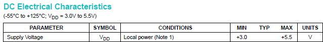
This is really strange... can you confirm it is the right markings on your TO-92 package (actually a temp sensor)?
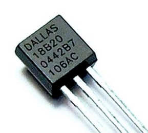
You could try changing the pin to exclude a pro mini failure (if you have not swapped that one already)
#define ONE_WIRE_BUS 3 // Pin where dallase sensor is connected
#define MAX_ATTACHED_DS18B20 16You can also test my Ds18b20 code from here but you need to change from RFM69 radio to Nrf24l01+ radio,
https://github.com/sundberg84/HomeAutomation/blob/master/Sketches MySensors RFM69 radio/RFM_BeerCooler_Temp/RFM_BeerCooler_Temp.inoI would also try a bare pro mini + the temp sensor + resistor on a breadboard powered with 3.3v from ftdi adapter.
I also need you to doublecheck the resistance on that pull-up resistor:
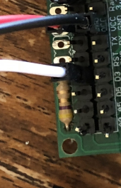
Im having a hard time to see the exact colors but it that is Yellow, Brown, Gold, Gold that means you have a 4.1 ohm resistor to VCC which is pretty much a short and might have broken the temp sensor. Use a 10k or 56k.
@sundberg84 Ok did try with just the bare pro mini + the temp sensor + resistor on a breadboard powered with 3.3v from ftdi adapter.
And guess what? Than I get the temperature reading :) So why is it not working on the board than? I Will check the soldering again and see if I can solder a new board.Dallas Temperature IC Control Library Demo Locating devices...Found 1 devices. Parasite power is: OFF Device 0 Address: 28FF5849011704D8 Device 0 Resolution: 9 Requesting temperatures...DONE Temp C: 21.00 Temp F: 69.80 Requesting temperatures...DONE Temp C: 21.00 Temp F: 69.80 Requesting temperatures...DONE Temp C: 21.00 Temp F: 69.80 Requesting temperatures...DONE Temp C: 21.00 Temp F: 69.80 Requesting temperatures...DONE Temp C: 21.00 Temp F: 69.80 Requesting temperatures...DONE Temp C: 21.00 Temp F: 69.80 Requesting temperatures...DONE ``` So both sensor and arduino are working? -
Promising! Then you know that hardware is ok... you just have to continue debugging.
Use the same hardware and software for the PCB. It should work just fine! (I have several working for years now). -
Hi All,
Thanks Sundberg84 for creating a board where I can knock out sensors in the matter of minutes instead of hours. :)
That being said, I actually spent many hours on the weekend trying to get my first board to work so I thought that I'd share so it could benefit others.
I was setting up a 3v3 board with 2 x AA batteries with the battery pad jumpered and using the 3v3 booster. I triple checked the board for continuity.
I was suffering from !TSM:FPAR:FAIL messages when firing up the node using the FTDI adaptor. I found that the board didn't work when both the battery and FTDI were supplying power.
Here are my lessons:
- You need to have a battery connected. This is required to power the radio, as it radio isn't powered by the FTDI adapter
- You need to remove power from the FTDI adapter. I couldn't disable power on my FTDI adapter so I had to use jumper wires for CTS, DTR, RXD, TXD, and GND between the adapter and the ProMini.
Thanks again, and I look forward to knocking out some nodes super quick.
Cheers,
Simon. -
-
@sundberg84 i think you already know the answer 😉 (not great regarding emi radiation for example,especially with cheap regulators and inductors.., one downside of relying on external parts,modules but i know your point it's for noobs..)
I seem to see another thing for your nrf ant, not sure if your nrf 24 goes outside the pcb,if it doesn't then this means you have gnd pour under the ant, not great too in this case -
how about swapping the Extra and Booster section? It makes it cleaner to connect the extra pins to the pro mini.
-
Thanks guys! (@scalz @gohan @dbemowsk !)
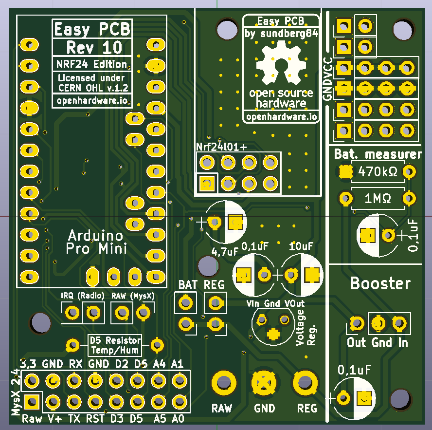
I think I will relocate the booster... should have thought about that before.
The NRF antenna goes outside the PCB just like rev 9 so no ground plain for the antenna in normal cases. I might revert it back to allow the PCB to be in range for all directions. Good point.I will start with to swap extra and booster to get as much space in between the antenna and inductor.
-
Something like this...
-
Hi all!
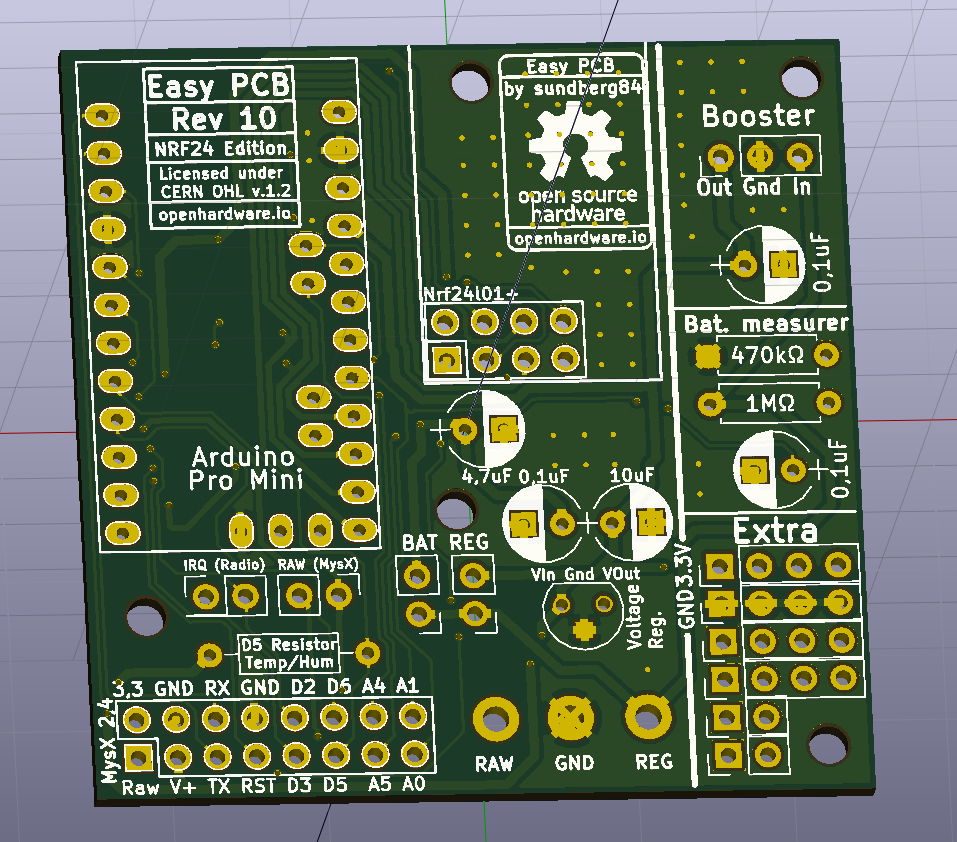
This has now been update to Rev 10.
New revision has been sent to PCB manufacturer but It will take some days for them to update their Gerber. (When you order, make sure it says M.Rev 6!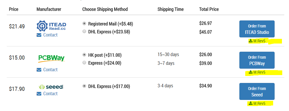
Openhardware page has been updated, let me know if you find anything strange.
RFM69 version will be updated soon as well.
-
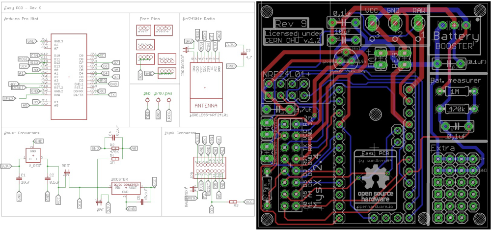
Can you please share design of version 9 of the Easy PCB NRF24 edition. I bought 10 pieces a while ago but just decided to use couple. Thank you.
@apl2017 what kind of info are you looking for ? Schematics ?
-
Just schematic and board layout, exactly what you placed, if possible in a bit better resolution. Thanks a lot!
@apl2017 traveling for my work until next week but will post then.
-
@sundberg84 I just finished my first battery sensor node based on the Easy PCB Rev 9. I have two questions i hope you can help me with:
The first is about the battery measurement. Because i didn't have a 0.1 uf lying around i used an 0.2 uf capacitor. I am using the following script to measure the battery.
//=========================
// BATTERY VOLTAGE DIVIDER SETUP
// 1M, 470K divider across battery and using internal ADC ref of 1.1V
// Sense point is bypassed with 0.1 uF cap to reduce noise at that point
// ((1e6+470e3)/470e3)*1.1 = Vmax = 3.44 Volts
// 3.44/1023 = Volts per bit = 0.003363075
#define VBAT_PER_BITS 0.003363075
#define VMIN 1.9                                  //  Vmin (radio Min Volt)=1.9V (564v)
#define VMAX 3.0                                  //  Vmax = (2xAA bat)=3.0V (892v)
int batteryPcnt = 0;                              // Calc value for battery %
int batLoop = 0;                                  // Loop to help calc average
int batArray[3];                                  // Array to store value for average calc.
int BATTERY_SENSE_PIN = A0;                       // select the input pin for the battery sense point
//=========================


   // Calculate the battery in %
   float Vbat  = sensorValue * VBAT_PER_BITS;
   int batteryPcnt = static_cast<int>(((Vbat-VMIN)/(VMAX-VMIN))*100.);
   Serial.print("Battery percent: "); Serial.print(batteryPcnt); Serial.println(" %");
Do i need to change anything in the formula? Because i getting reading around the 130%
Requesting temperature...DONE
Temperatuur : 26.62 Degrees C
11935 TSF:MSG:SEND,25-25-0-0,s=5,c=1,t=0,pt=7,l=5,sg=0,ft=0,st=OK:26.6
Battery percent: 131 %
Battery Voltage: 3.35 V
Sleep...
12945 MCO:SLP:MS=900000,SMS=0,I1=0,M1=1,I2=254,M2=1
12955 TSF:TDI:TSL
If i use the following method:
//----
   // 1M, 470K divider across battery and using internal ADC ref of 1.1V
   // Sense point is bypassed with 0.1 uF cap to reduce noise at that point
   // ((1e6+470e3)/470e3)*1.1 = Vmax = 3.44 Volts
   // 3.44/1023 = Volts per bit = 0.003363075
   float batteryV  = sensorValue * 0.003363075;
   int batteryPcntNEW = sensorValue / 10;

   Serial.print("Battery percent: ");
   Serial.print(batteryPcntNEW);
   Serial.println(" %");
//----
I am getting: (this is expected, because batteries are new)
Battery percent: 99 %
Sleep...
12945 MCO:SLP:MS=900000,SMS=0,I1=0,M1=1,I2=254,M2=1
12955 TSF:TDI:TSL
My second question is about casing: any tips on which case to use which fit your board and a battery pack? and is as small as possible? Do you perhaps have links of your favourite (Chinese) sellers?
@mister_ik said in 💬 Easy/Newbie PCB for MySensors:
@sundberg84 I just finished my first battery sensor node based on the Easy PCB Rev 9. I have two questions i hope you can help me with:
The first is about the battery measurement. Because i didn't have a 0.1 uf lying around i used an 0.2 uf capacitor. I am using the following script to measure the battery.
Do i need to change anything in the formula? Because i getting reading around the 130%
Hello, this is normal as your maximum voltage is set at 3V, while initial voltage of an alkaline AA/AAA cell can be a bit over 1.6V. But voltage will quickly drop toward 1.5V (much faster than remaining capacity), so the best instead of changing the maximum voltage is to check the value of batteryPcnt and if it's over 100, just set it to 100.
Make sure the VBAT_PER_BITS makes you read a voltage that matches the voltage you read with your multimeter, else fix it. Each Atmega is different so you need to calibrate each board.For the capacitor it's not a problem, it's just made to stabilize the voltage as it's very sensible to electrical noise. Twice the value will be good enough for this job :)
-
@sundberg84 I just finished my first battery sensor node based on the Easy PCB Rev 9. I have two questions i hope you can help me with:
The first is about the battery measurement. Because i didn't have a 0.1 uf lying around i used an 0.2 uf capacitor. I am using the following script to measure the battery.
//=========================
// BATTERY VOLTAGE DIVIDER SETUP
// 1M, 470K divider across battery and using internal ADC ref of 1.1V
// Sense point is bypassed with 0.1 uF cap to reduce noise at that point
// ((1e6+470e3)/470e3)*1.1 = Vmax = 3.44 Volts
// 3.44/1023 = Volts per bit = 0.003363075
#define VBAT_PER_BITS 0.003363075
#define VMIN 1.9                                  //  Vmin (radio Min Volt)=1.9V (564v)
#define VMAX 3.0                                  //  Vmax = (2xAA bat)=3.0V (892v)
int batteryPcnt = 0;                              // Calc value for battery %
int batLoop = 0;                                  // Loop to help calc average
int batArray[3];                                  // Array to store value for average calc.
int BATTERY_SENSE_PIN = A0;                       // select the input pin for the battery sense point
//=========================


   // Calculate the battery in %
   float Vbat  = sensorValue * VBAT_PER_BITS;
   int batteryPcnt = static_cast<int>(((Vbat-VMIN)/(VMAX-VMIN))*100.);
   Serial.print("Battery percent: "); Serial.print(batteryPcnt); Serial.println(" %");
Do i need to change anything in the formula? Because i getting reading around the 130%
Requesting temperature...DONE
Temperatuur : 26.62 Degrees C
11935 TSF:MSG:SEND,25-25-0-0,s=5,c=1,t=0,pt=7,l=5,sg=0,ft=0,st=OK:26.6
Battery percent: 131 %
Battery Voltage: 3.35 V
Sleep...
12945 MCO:SLP:MS=900000,SMS=0,I1=0,M1=1,I2=254,M2=1
12955 TSF:TDI:TSL
If i use the following method:
//----
   // 1M, 470K divider across battery and using internal ADC ref of 1.1V
   // Sense point is bypassed with 0.1 uF cap to reduce noise at that point
   // ((1e6+470e3)/470e3)*1.1 = Vmax = 3.44 Volts
   // 3.44/1023 = Volts per bit = 0.003363075
   float batteryV  = sensorValue * 0.003363075;
   int batteryPcntNEW = sensorValue / 10;

   Serial.print("Battery percent: ");
   Serial.print(batteryPcntNEW);
   Serial.println(" %");
//----
I am getting: (this is expected, because batteries are new)
Battery percent: 99 %
Sleep...
12945 MCO:SLP:MS=900000,SMS=0,I1=0,M1=1,I2=254,M2=1
12955 TSF:TDI:TSL
My second question is about casing: any tips on which case to use which fit your board and a battery pack? and is as small as possible? Do you perhaps have links of your favourite (Chinese) sellers?
@Nca78 thanks for the help/answer. 😀 About the case I'm using some plastic electronic cases from my hardware shop but @ openhardware you will find some links to 3d projects.
Let us know @Mister_ik if you need anything else.
-
No sign of the new revision yet:

-
No sign of the new revision yet:
@mickecarlsson - not on the RFM69 version, no. PCBway has updated the NRF24 version so a good sign.
Something went wrong with the update of the RFM69 version so I had to activate it 21hours ago: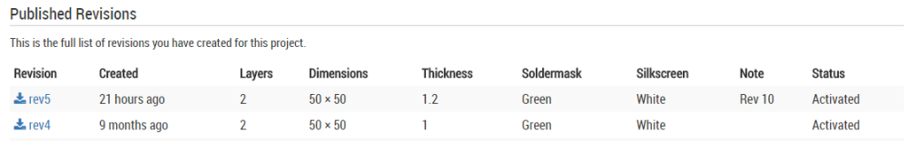
Lets hope PCBway picks this up today.
Hello! It looks like you're interested in this conversation, but you don't have an account yet.
Getting fed up of having to scroll through the same posts each visit? When you register for an account, you'll always come back to exactly where you were before, and choose to be notified of new replies (either via email, or push notification). You'll also be able to save bookmarks and upvote posts to show your appreciation to other community members.
With your input, this post could be even better 💗
Register Login