💬 Easy/Newbie PCB for MySensors
-
@mickecarlsson - not on the RFM69 version, no. PCBway has updated the NRF24 version so a good sign.
Something went wrong with the update of the RFM69 version so I had to activate it 21hours ago: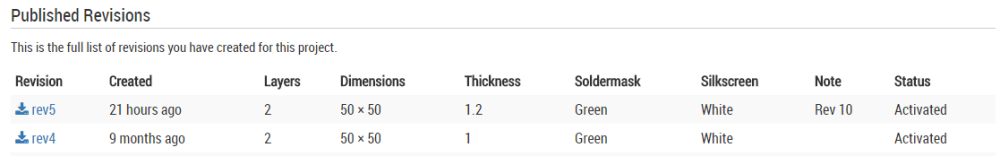
Lets hope PCBway picks this up today.
@sundberg84
OK, good news. I will check it tomorrow and hopefully order a batch (or two). -
Still no rev 6 on itead or pcbway for rfm69 version :-(
-
Still no rev 6 on itead or pcbway for rfm69 version :-(
@mickecarlsson no something went wrong so Rev 5 is ok to order! This is easy rev 10!
-
Hello @sundberg84
What if feeding a Pro Mini 3.3V (EasyPCB Nrf24l01+ edition rev 10) with regulated power on RAW. (I have 5 VDC). I guess I can feed the radio via the VCC terminal instead of using an external voltage regulator. Can the EasyPCB be used in such a setup?
Edit: To answer my own question. I should RTFM :facepunch:
It states clearly that:
"(If you are using regulated 3.3v, use 5v instructions but skip the voltage regulator and bypass this with a jumper between Vin and Vout"
Thanks anyway!
@รอเร-อ I have a similar need, but not exactly the same.
My power route is:
18650 Lipo (2.7 - 4.2 V) -> TP4056 (charger) -> Booster (5V) -> Raw pin of pro mini 3.3V -> Vcc of pro mini 3.3V -> Radio (NRF24)In my case the easy newbie pcb is not directly suitable because the Vout of the Booster is connected to Vcc instead of raw.
So my idea is to use a modified version of the easy newbie pcb with the schematic posted here
in order to have more flexibility in the power options.Actually I don't have the skills to design a pcb, but maybe, if the idea is good, someone else could design it.
This schematic is compatible with all the power options actually supported by the easy newbie pcb, and supports also new possibility, simply changing a couple of jumpers
-
Hello @franz-unix, can't you just bend the output pin of the booster at 90° and solder a wire from it to the raw pin ?
-
@nca78 Yes it should work.
If I connect the output of the tp4056 to the gnd and reg input of the screw terminal of the easy newbie pcb and then I run a wire from the Vout of the booster to the raw input of the screw terminal, the final result is also quite clean and it is not necessary to solder the wire directly on the pro mini.
I think that, in this case, the reg jumper must be NOT shortened.
-
Hi,
I ordered 10 PCBs using "Order from PCBWay" button. It only asked me about PayPal card and din't require any registration on PCBWay. So, everything looks good, PayPal transaction is completed. Can somebody tell me please how can I track it? Probably I'm missing tracking option somewhere... Thank you!
P.S.
Cant wait to try it out. :) -
Hi,
I ordered 10 PCBs using "Order from PCBWay" button. It only asked me about PayPal card and din't require any registration on PCBWay. So, everything looks good, PayPal transaction is completed. Can somebody tell me please how can I track it? Probably I'm missing tracking option somewhere... Thank you!
P.S.
Cant wait to try it out. :)@zelen I'm not sure. You didn't receive any email? I normally get a email once they are finished and shipped with tracking.
-
@zelen I'm not sure. You didn't receive any email? I normally get a email once they are finished and shipped with tracking.
@sundberg84 thank you for clarification. I expected email right after making an order. So, I will wait for finishing production and shipment.
-
I use some of old rev8 boards. I have noticed that I use a ceramic capacitor instead of an electric capacitor compared to the images for the battery measurement. Does it matter? Or should I replace the ceramic capacitor (104) with an electric capacitor?
-
I use some of old rev8 boards. I have noticed that I use a ceramic capacitor instead of an electric capacitor compared to the images for the battery measurement. Does it matter? Or should I replace the ceramic capacitor (104) with an electric capacitor?
@harrdy should work just fine.
-
I use some of old rev8 boards. I have noticed that I use a ceramic capacitor instead of an electric capacitor compared to the images for the battery measurement. Does it matter? Or should I replace the ceramic capacitor (104) with an electric capacitor?
-
Hello @sundberg84, I would like to buy the Easy/Newbie PCB for MySensors but I have a few questions
I want to use it the 5V Arduino Pro mini not the 3V version
I also want to use the battery monitor
Is it ok or should I modify "something"
Also all the pcbs have the battery "expansion: or not?
Thanks, Emmanuel -
Hello @sundberg84, I would like to buy the Easy/Newbie PCB for MySensors but I have a few questions
I want to use it the 5V Arduino Pro mini not the 3V version
I also want to use the battery monitor
Is it ok or should I modify "something"
Also all the pcbs have the battery "expansion: or not?
Thanks, EmmanuelI want to use it the 5V Arduino Pro mini not the 3V version
Then you need to use the nrf24l01+ version, that works fine - the RFM69 version needs a 3.3v Pro Mini only.
I also want to use the battery monitor
As @gohan said - don't use batteries on a 5v node. Use a 3.3v because it will use up your batteries very quickly. See the guides i have on openhardware for different modes on my PCB.
Is it ok or should I modify "something"
Also all the pcbs have the battery "expansion: or not?"something" is hard to understand, you can modify i many different ways depending on what you want to do. All the basic "modifications" can be found if you read the project page on openhardware.io
Controller: Proxmox VM - Home Assistant
MySensors GW: Arduino Uno - W5100 Ethernet, Gw Shield Nrf24l01+ 2,4Ghz
MySensors GW: Arduino Uno - Gw Shield RFM69, 433mhz
RFLink GW - Arduino Mega + RFLink Shield, 433mhz -
I want to use it the 5V Arduino Pro mini not the 3V version
Then you need to use the nrf24l01+ version, that works fine - the RFM69 version needs a 3.3v Pro Mini only.
I also want to use the battery monitor
As @gohan said - don't use batteries on a 5v node. Use a 3.3v because it will use up your batteries very quickly. See the guides i have on openhardware for different modes on my PCB.
Is it ok or should I modify "something"
Also all the pcbs have the battery "expansion: or not?"something" is hard to understand, you can modify i many different ways depending on what you want to do. All the basic "modifications" can be found if you read the project page on openhardware.io
@sundberg84 thanks for your response
If I don't care about battery consumption can I still view and use the battery monitor to be alarmed when battery is empty? -
@sundberg84 thanks for your response
If I don't care about battery consumption can I still view and use the battery monitor to be alarmed when battery is empty?@manos yes you can.
Hello! It looks like you're interested in this conversation, but you don't have an account yet.
Getting fed up of having to scroll through the same posts each visit? When you register for an account, you'll always come back to exactly where you were before, and choose to be notified of new replies (either via email, or push notification). You'll also be able to save bookmarks and upvote posts to show your appreciation to other community members.
With your input, this post could be even better 💗
Register Login