
Triple Axis Compass Sensor for mailbox?
-
Yes, a magnet-switch would probably work. But my main concern regarding the magnet-switch is that I sometimes receives rather large parcels witch are jammed down the mailbox and would possible break of any magnet-switch that are placed inside the mailbox. The lid is where any sensor would be most protected. I might go with the simple magnet switch method to try out the durability but I would like to know if there are any options.
Would the Triple Axis Accelerometer from the mysensors-shop link work with just waking up when lid is moved? Or could a PIR be able to use interrupt to wake up?
-
-
-
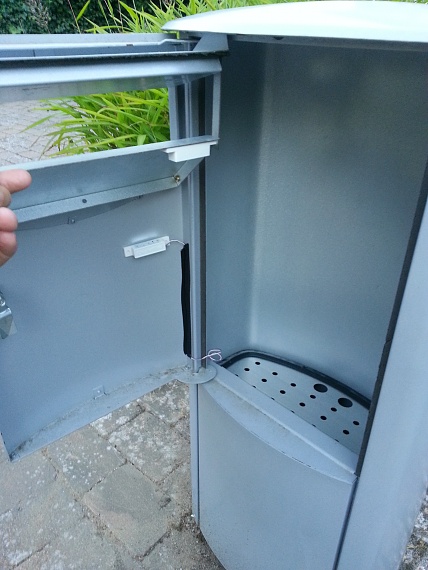
My mailbox kid of looks like this:

-
@Yveaux said:
@Cliff-Karlsson Could you post a real picture and draw where you would mount the compass sensor?
It looks similar to this one and I would place everything inside a sealed plastic box glued to the top of the lid if that kind of sensor is a good idea battery-wise.

-
@Yveaux said:
@Cliff-Karlsson Could you post a real picture and draw where you would mount the compass sensor?
It looks similar to this one and I would place everything inside a sealed plastic box glued to the top of the lid if that kind of sensor is a good idea battery-wise.
-
Ahhh, that idea did not strike me that I could use a different neodymium magnet instead of the one that was shipped with the magnet-switch. I guess that I just can place a strong magnet on the side of the mailbox. No glue needed as I almost break my nails of when trying to get those 20x3(?)mm magnets of my refridgerator
-
Ahhh, that idea did not strike me that I could use a different neodymium magnet instead of the one that was shipped with the magnet-switch. I guess that I just can place a strong magnet on the side of the mailbox. No glue needed as I almost break my nails of when trying to get those 20x3(?)mm magnets of my refridgerator
-
I want to try to build simple sensor using the door/window/button sketch:
#include <MySensor.h>
#include <SPI.h>
#include <Bounce2.h>

#define CHILD_ID 3
#define BUTTON_PIN  3  // Arduino Digital I/O pin for button/reed switch

MySensor gw;
Bounce debouncer = Bounce();
int oldValue=-1;

// Change to V_LIGHT if you use S_LIGHT in presentation below
MyMessage msg(CHILD_ID,V_TRIPPED);

void setup()
{
  gw.begin();

 // Setup the button
  pinMode(BUTTON_PIN,INPUT);
  // Activate internal pull-up
  digitalWrite(BUTTON_PIN,HIGH);

  // After setting up the button, setup debouncer
  debouncer.attach(BUTTON_PIN);
  debouncer.interval(5);

  // Register binary input sensor to gw (they will be created as child devices)
  // You can use S_DOOR, S_MOTION or S_LIGHT here depending on your usage.
  // If S_LIGHT is used, remember to update variable type you send in. See "msg" above.
  gw.present(CHILD_ID, S_DOOR);
}


//  Check if digital input has changed and send in new value
void loop()
{
  debouncer.update();
  // Get the update value
  int value = debouncer.read();

  if (value != oldValue) {
     // Send in the new value
     gw.send(msg.set(value==HIGH ? 1 : 0));
     oldValue = value;
  }
}
And also add the battery masuring from :
#include <SPI.h>
#include <MySensor.h>

#define round(x) ((x)>=0?(long)((x)+0.5):(long)((x)-0.5))
#define N_ELEMENTS(array) (sizeof(array)/sizeof((array)[0]))

#define CHILD_ID_MOISTURE 0
#define CHILD_ID_BATTERY 1
#define SLEEP_TIME 1800000 // Sleep time between reads (in milliseconds)
#define THRESHOLD 1.1 // Only make a new reading with reverse polarity if the change is larger than 10%.
#define STABILIZATION_TIME 1000 // Let the sensor stabilize before reading
#define BATTERY_FULL 3143 // 2xAA usually give 3.143V when full
#define BATTERY_ZERO 2340 // 2.34V limit for 328p at 8MHz. 1.9V, limit for nrf24l01 without step-up. 2.8V limit for Atmega328 with default BOD settings.
const int SENSOR_ANALOG_PINS[] = {A0, A1}; // Sensor is connected to these two pins. Avoid A3 if using ATSHA204. A6 and A7 cannot be used because they don't have pullups.

MySensor gw;
MyMessage msg(CHILD_ID_MOISTURE, V_HUM);
MyMessage voltage_msg(CHILD_ID_BATTERY, V_VOLTAGE);
long oldvoltage = 0;
byte direction = 0;
int oldMoistureLevel = -1;

void setup()
{
  gw.begin();

  gw.sendSketchInfo("Plant moisture w bat", "1.5");

  gw.present(CHILD_ID_MOISTURE, S_HUM);
  delay(250);
  gw.present(CHILD_ID_BATTERY, S_CUSTOM);
  for (int i = 0; i < N_ELEMENTS(SENSOR_ANALOG_PINS); i++) {
    pinMode(SENSOR_ANALOG_PINS[i], OUTPUT);
    digitalWrite(SENSOR_ANALOG_PINS[i], LOW);
  }
}

void loop()
{
  int moistureLevel = readMoisture();

  // Send rolling average of 2 samples to get rid of the "ripple" produced by different resistance in the internal pull-up resistors
  // See http://forum.mysensors.org/topic/2147/office-plant-monitoring/55 for more information
  if (oldMoistureLevel == -1) { // First reading, save current value as old
    oldMoistureLevel = moistureLevel;
  }
  if (moistureLevel > (oldMoistureLevel * THRESHOLD) || moistureLevel < (oldMoistureLevel / THRESHOLD)) {
    // The change was large, so it was probably not caused by the difference in internal pull-ups.
    // Measure again, this time with reversed polarity.
    moistureLevel = readMoisture();
  }
  gw.send(msg.set((moistureLevel + oldMoistureLevel) / 2.0 / 10.23, 1));
  oldMoistureLevel = moistureLevel;
  long voltage = readVcc();
  if (oldvoltage != voltage) { // Only send battery information if voltage has changed, to conserve battery.
    gw.send(voltage_msg.set(voltage / 1000.0, 3)); // redVcc returns millivolts. Set wants volts and how many decimals (3 in our case)
    gw.sendBatteryLevel(round((voltage - BATTERY_ZERO) * 100.0 / (BATTERY_FULL - BATTERY_ZERO)));
    oldvoltage = voltage;
  }
  gw.sleep(SLEEP_TIME);
}

int readMoisture() {
  pinMode(SENSOR_ANALOG_PINS[direction], INPUT_PULLUP); // Power on the sensor
  analogRead(SENSOR_ANALOG_PINS[direction]);// Read once to let the ADC capacitor start charging
  gw.sleep(STABILIZATION_TIME);
  int moistureLevel = (1023 - analogRead(SENSOR_ANALOG_PINS[direction]));

  // Turn off the sensor to conserve battery and minimize corrosion
  pinMode(SENSOR_ANALOG_PINS[direction], OUTPUT);
  digitalWrite(SENSOR_ANALOG_PINS[direction], LOW);

  direction = (direction + 1) % 2; // Make direction alternate between 0 and 1 to reverse polarity which reduces corrosion
  return moistureLevel;
}

long readVcc() {
  // From http://provideyourown.com/2012/secret-arduino-voltmeter-measure-battery-voltage/
  // Read 1.1V reference against AVcc
  // set the reference to Vcc and the measurement to the internal 1.1V reference
#if defined(__AVR_ATmega32U4__) || defined(__AVR_ATmega1280__) || defined(__AVR_ATmega2560__)
  ADMUX = _BV(REFS0) | _BV(MUX4) | _BV(MUX3) | _BV(MUX2) | _BV(MUX1);
#elif defined (__AVR_ATtiny24__) || defined(__AVR_ATtiny44__) || defined(__AVR_ATtiny84__)
  ADMUX = _BV(MUX5) | _BV(MUX0);
#elif defined (__AVR_ATtiny25__) || defined(__AVR_ATtiny45__) || defined(__AVR_ATtiny85__)
  ADMUX = _BV(MUX3) | _BV(MUX2);
#else
  ADMUX = _BV(REFS0) | _BV(MUX3) | _BV(MUX2) | _BV(MUX1);
#endif

  delay(2); // Wait for Vref to settle
  ADCSRA |= _BV(ADSC); // Start conversion
  while (bit_is_set(ADCSRA, ADSC)); // measuring

  uint8_t low  = ADCL; // must read ADCL first - it then locks ADCH
  uint8_t high = ADCH; // unlocks both

  long result = (high << 8) | low;

  result = 1125300L / result; // Calculate Vcc (in mV); 1125300 = 1.1*1023*1000
  return result; // Vcc in millivolts
}
Do I "just" add these parts to the first sketch to have battery measuring working:
#define CHILD_ID_BATTERY 1 #define BATTERY_FULL 3143 // 2xAA usually give 3.143V when full #define BATTERY_ZERO 2340 MyMessage voltage_msg(CHILD_ID_BATTERY, V_VOLTAGE); long oldvoltage = 0; gw.present(CHILD_ID_BATTERY, S_CUSTOM); long voltage = readVcc(); if (oldvoltage != voltage) { // Only send battery information if voltage has changed, to conserve battery. gw.send(voltage_msg.set(voltage / 1000.0, 3)); // redVcc returns millivolts. Set wants volts and how many decimals (3 in our case) gw.sendBatteryLevel(round((voltage - BATTERY_ZERO) * 100.0 / (BATTERY_FULL - BATTERY_ZERO))); oldvoltage = voltage; long readVcc() { // From http://provideyourown.com/2012/secret-arduino-voltmeter-measure-battery-voltage/ // Read 1.1V reference against AVcc // set the reference to Vcc and the measurement to the internal 1.1V reference #if defined(__AVR_ATmega32U4__) || defined(__AVR_ATmega1280__) || defined(__AVR_ATmega2560__) ADMUX = _BV(REFS0) | _BV(MUX4) | _BV(MUX3) | _BV(MUX2) | _BV(MUX1); #elif defined (__AVR_ATtiny24__) || defined(__AVR_ATtiny44__) || defined(__AVR_ATtiny84__) ADMUX = _BV(MUX5) | _BV(MUX0); #elif defined (__AVR_ATtiny25__) || defined(__AVR_ATtiny45__) || defined(__AVR_ATtiny85__) ADMUX = _BV(MUX3) | _BV(MUX2); #else ADMUX = _BV(REFS0) | _BV(MUX3) | _BV(MUX2) | _BV(MUX1); #endif delay(2); // Wait for Vref to settle ADCSRA |= _BV(ADSC); // Start conversion while (bit_is_set(ADCSRA, ADSC)); // measuring uint8_t low = ADCL; // must read ADCL first - it then locks ADCH uint8_t high = ADCH; // unlocks both long result = (high << 8) | low; result = 1125300L / result; // Calculate Vcc (in mV); 1125300 = 1.1*1023*1000 return result; // Vcc in millivolts } -
I used the BinarySwitchSleepSensor sketch and tried adding the battery measuring info. Does this look ok If I only want the sensor to sleep until the magnetswitch attached to PIN 2 is opened and every 6h it reports battery?
// Enable debug prints to serial monitor
#define MY_DEBUG
#define SLEEP_TIME 21600000 // Sleep time between reads (in milliseconds)
// Enable and select radio type attached
#define MY_RADIO_NRF24
//#define MY_RADIO_RFM69

#include <SPI.h>
#include <MySensor.h>

#define SKETCH_NAME "Mailbox +Battery"
#define SKETCH_MAJOR_VER "1"
#define SKETCH_MINOR_VER "0"

#define PRIMARY_CHILD_ID 3
#define CHILD_ID_BATTERY 1

#define BATTERY_FULL 3143 // 2xAA usually give 3.143V when full
#define BATTERY_ZERO 2340

#define PRIMARY_BUTTON_PIN 2   // Arduino Digital I/O pin for button/reed switch


// Change to V_LIGHT if you use S_LIGHT in presentation below
MyMessage msg(PRIMARY_CHILD_ID, V_TRIPPED);
MyMessage voltage_msg(CHILD_ID_BATTERY, V_VOLTAGE);
long oldvoltage = 0;

void setup()
{
  // Setup the buttons
  pinMode(PRIMARY_BUTTON_PIN, INPUT);


  // Activate internal pull-ups
  digitalWrite(PRIMARY_BUTTON_PIN, HIGH);

}

void presentation() {
  // Send the sketch version information to the gateway and Controller
  sendSketchInfo(SKETCH_NAME, SKETCH_MAJOR_VER "." SKETCH_MINOR_VER);

  // Register binary input sensor to sensor_node (they will be created as child devices)
  // You can use S_DOOR, S_MOTION or S_LIGHT here depending on your usage.
  // If S_LIGHT is used, remember to update variable type you send in. See "msg" above.
  present(PRIMARY_CHILD_ID, S_DOOR);
  delay(250);
  present(CHILD_ID_BATTERY, S_CUSTOM);
}

// Loop will iterate on changes on the BUTTON_PINs
void loop()
{
  uint8_t value;
  static uint8_t sentValue=2;

  // Short delay to allow buttons to properly settle
  sleep(5);

  value = digitalRead(PRIMARY_BUTTON_PIN);

  if (value != sentValue) {
     // Value has changed from last transmission, send the updated value
     send(msg.set(value==HIGH ? 1 : 0));
     sentValue = value;
  }
long voltage = readVcc();
  if (oldvoltage != voltage) { // Only send battery information if voltage has changed, to conserve battery.
    send(voltage_msg.set(voltage / 1000.0, 3)); // redVcc returns millivolts. Set wants volts and how many decimals (3 in our case)
    sendBatteryLevel(round((voltage - BATTERY_ZERO) * 100.0 / (BATTERY_FULL - BATTERY_ZERO)));
    oldvoltage = voltage;
  }


  // Sleep until something happens with the sensor
  sleep(PRIMARY_BUTTON_PIN-2, CHANGE, SLEEP_TIME);
}

long readVcc() {
  // From http://provideyourown.com/2012/secret-arduino-voltmeter-measure-battery-voltage/
  // Read 1.1V reference against AVcc
  // set the reference to Vcc and the measurement to the internal 1.1V reference
#if defined(__AVR_ATmega32U4__) || defined(__AVR_ATmega1280__) || defined(__AVR_ATmega2560__)
  ADMUX = _BV(REFS0) | _BV(MUX4) | _BV(MUX3) | _BV(MUX2) | _BV(MUX1);
#elif defined (__AVR_ATtiny24__) || defined(__AVR_ATtiny44__) || defined(__AVR_ATtiny84__)
  ADMUX = _BV(MUX5) | _BV(MUX0);
#elif defined (__AVR_ATtiny25__) || defined(__AVR_ATtiny45__) || defined(__AVR_ATtiny85__)
  ADMUX = _BV(MUX3) | _BV(MUX2);
#else
  ADMUX = _BV(REFS0) | _BV(MUX3) | _BV(MUX2) | _BV(MUX1);
#endif

  delay(2); // Wait for Vref to settle
  ADCSRA |= _BV(ADSC); // Start conversion
  while (bit_is_set(ADCSRA, ADSC)); // measuring

  uint8_t low  = ADCL; // must read ADCL first - it then locks ADCH
  uint8_t high = ADCH; // unlocks both

  long result = (high << 8) | low;

  result = 1125300L / result; // Calculate Vcc (in mV); 1125300 = 1.1*1023*1000
  return result; // Vcc in millivolts
}



Hello! It looks like you're interested in this conversation, but you don't have an account yet.
Getting fed up of having to scroll through the same posts each visit? When you register for an account, you'll always come back to exactly where you were before, and choose to be notified of new replies (either via email, or push notification). You'll also be able to save bookmarks and upvote posts to show your appreciation to other community members.
With your input, this post could be even better 💗
Register Login