πŸ’¬ Distance Sensor


  • Admin

    This thread contains comments for the article "Distance Sensor" posted on MySensors.org.


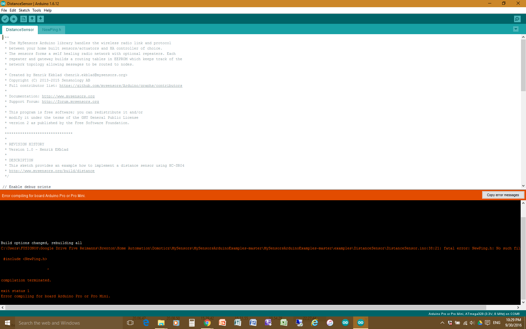
  • Hi there, i've just got a couple JSN-SR04T distance ultrasonic sensors in the post today. Was excited to sit down and make up my first go at a distance sensor to measure our water tank level, but when i went in to the mysensors master directory to find the example sketch for distance sensor i couldn't find one. So i copied the one from https://www.mysensors.org/build/distance but this is an old version and when i complied it in the Arduino IDE i had an error come up not recognising "NewPing.h". Any pointers where to go from here please??


  • Admin


  • Thanks @hek for your prompt reply. I went there and downloaded the "MySensorsArduinoExamples". I still can't seem to get "DistanceSensor" sketch to compile. It's still looking for NewPing.h even though it's in the directory!

    What am I missing?

    0_1475240351494_upload-e54e5fc0-bfc0-43ae-9f99-4d5cfcaea3ad


  • Admin

    Looks like you placed the NewPing library in the wrong place. Check the path in the Arduino IDE preferences.


  • Get this error

    C:\Users\Daan\AppData\Local\Temp\Rar$DIa0.647\DistanceSensor\DistanceSensor.ino: In function 'void setup()':

    DistanceSensor:53: error: 'getConfig' was not declared in this scope

    metric = getConfig().isMetric;


  • Mod


  • hi folks, has anyone ever tried/considered to run this sensor on a battery powered node? Does it make sense, what would be a good setup? I want to monitor a remote watertank where it's hard to get power to... Thanks for your expert thoughts on this!


  • Hero Member

    @jjk There should be no problem running it from a battery if you only want to check a few times a day and sleep the node in between, but depending on how often you want it to check the level you may need to also have a small solar panel perhaps.

    You might also like to search for some of the other threads on battery powered nodes for info on how to reduce power consumption.

    I have just installed an ultrasonic level on my tank last weekend but I have power there for the pump so the node runs all the time.


  • thanks, sounds good, I will give it a trg


  • i ran it but i see garbage in com monitor?? what is wrong?


  • I have a setup with a HC-SR04 connected to an Arduino Pro Mini via a cable of about 5m length As I'm getting inconsistent readings from the sensor, I was wondering if cable length could be an issue - and if so, what a possible workaround could look like. Any thoughts from the experts?


  • Mod

    @jjk did it work better when you used a shorter cable?


  • @Boots33 I had looked at the exact same scenario as jjk, and although the intended 3.3v rfm69 node is pre-designed for low consumption (Whisper), my problem lay in the ultrasonic (DYP-ME007Y mounted on a tube inserted through the concrete roof) for hourly reports as it is 5v, as is the SR04. They can be triggered by 3.3v but not run. The standby current of a 5v booster proved too much, so resorted to a 3v 33mA latching relay to fire it up. It has all been a design exercise to date, but if my calcs are correct the node should run for a year on 3 alkalines with the US running once every hour triggered by RTC.


  • @mfalkvidd that's a fair question... I tested the sketch and connectivity with dupont cables and my spontaneous answer would be, "yes". However, to be honest, I never really calibrated the distance readings nor did I do a long-term test in the lab setup, so I think the true answer is, " I don't know"...

    @zboblamont sounds like you figured it out?! Would you mind providing details on the relay you have used?


  • @jjk Kemet EC2-3SNU from memory, but I know Omron et al make them also, check on Mouser etc. as it is not heavy current. The point is to ensure it is a latching type, the 33mA consumption from memory is ca 30ms, reverse pin polarity to reset relay, other may have dual coil.


  • thanks @ zboblamont, I will have a look


  • @jjk As an afterthought - If large temperature fluctuations are not an issue (air expansion in a tube) and it is not dirty water, you might also consider using differential pressure sensors as these are reasonably easy and can operate directly at 3.3v, inc I2C.


  • @zboblamont thanks for putting more thoughts into this for me!
    As I'm just an motivated hobbyist (far from being expert in electronics), I've tried to switch the pro mini to a nano, in a hope that keeps me from dealing with the relay (new to me). My thought was that the 5V it provides should mitigate the issue - looks like it doesn't. So if the readings aren't getting more consistent with the 5V Nano, what else could be the issue?


  • @jjk Hey, no expertise here either, hobbyist also, I am just old school measure thrice cut once. To be clear, I am fixed on a low voltage node so the relay gives the US board a solid and separate 5v, as I read that some of these are power sensitive, and some folks had problems powering them from an Arduino. The US trigger is supposedly ok at 3v, I only need to voltage divide the signal to the Mini. But that is my scenario, low power reliability.

    In your situation, I would restore everything to completely original in a test space, use separate supplies and run checks. If the board is faulty the inconsistencies should still be there. If not, introduce each variable methodically to identify the cause.


  • @zboblamont thanks and yes, that's exactly what I doing... I have take. everything down and will look into a detailed test setup over the weekend. Will post any findings πŸ˜‰


  • o.k. here's an update for those who are interested...
    I have completely take down the components and resembled the setup in a test environment with a newly created prototype pcb. It works as expected - kind of. What I found is that the SR04 seems to be very sensitive to weak electrical connections. At first, I had a similar effect of inconsistent readings in the test and was about to conclude that there must be a piece of hardware at fault. Then I found a cable poorly soldered to the pcb and after fixing that, voila, the readings were consistent over 50 or so samples.
    Another source of headache is probably that I have used pin headers to easily connect/exchange the components and my observation is that there, too seems to be a certain sensitivity in "quality of craftsmanship". After about half day of running the test setup, I got unable to read errors from a DHT22 that is also attached to the node. I inspected everything and it looked good, but only after pushing firmly of the Nano (that looked like it was perfectly sitting in it's header), the readings came back o.k.
    Now trying to figure out how to bring that into the outside world where eventually I will have to deal with temperature changes that I suspect might further contribute to the issue...


  • @jjk @jjk Well, at least the issue is resolved, annoying but at least you found it. I thought these boards had some temperature compensation incorporated, but unless the distance is critical it should not cause dramatic shifts anyway.
    Out of curiosity, I have seen these particular devices described as JSN-SR04T and DYP-ME007Y, and I note on another thread that a JSN-SR04T-2.0 version which was otherwise identical but would not respond as expected. What is the type you are using?


  • @zboblamont the temperature issue I'm expecting is mainly wrt the electrical connections and the components sitting tightly (or not) in the pin headers. However, I guess only time will tell whether or not that becomes an issue πŸ˜‰ The SR04 is labeled "HC-SR04" and I got it from Amazon. The accuracy is "ok", I'd say. I did some reference measurements with a tape measure and below 1m the sensor returned consistently correct readings. Beginning at about 1.5-2m the readings occasionally would fluctuate by +/- 1cm, but on average it is o.k. As I intend to use it as a "general level indicator" in my grey water tank that's good enough for me - if I get it to work properly.


  • @jjk said in πŸ’¬ Distance Sensor:

    HC-SR04

    Ooops, my apologies, the thread began with the JSN, I didn't pick up on you were referring to the HC until now and I read back.
    I was looking to deploy ultrasonics in a sewage holding tank and a raw water storage tank and looked at these devices, but had misgivings over the high humidity and -20 winters here with the dual sensor and PCB. It is stated that the membranes of the transducer are waterproof, so if you can seal the PCB and connectors they should work fine.

    There are already two types turn up for the JSN type single transducer, one PCB mounted the other on a long cable, per link text . Now it seems there is a version 2.0 which is not work as per the original, so putting ordering on hold until this is resolved or the exact version is known to the supplier.

    Will be interesting to see if you get it to work reliably in your scenario.


  • @zboblamont lol, yeah that can happen with all the wonderful acronyms we have to deal with πŸ™‚
    I had played with a JSN-SR04T (cable version) a while ago, but was very disappointed with accuracy and consistency, which also seems to be in line with most online ratings. So I switched to the HC-SR04 which worked well in another (indoor) setup. I'm not sure how that sensor will do in the water tank, but since it will always be at least 1m above the water level, I'm hoping it'll do o.k. - Will report once I got it working and then how it does over time...


  • o.k. folks, here's another update. Thanks to a number of rainy days, I have worked on the setup in my lab environment, even got myself a fritzing pcb to make things a bit more stable. Indoors, with a new sensor, things worked out o.k., the readings were stable. With the sun back in our area, brought everything out to the tank. First finding: I proved the sensor that was still out there was faulty! Now everything is installed, readings are transmitted every 15 minutes. That's the good news. The bad news is, the readings are again not consistent! The following is a list of the last 20 or so readings:

    120
    86
    82
    84
    85
    67
    0
    82
    85
    80
    84
    126
    84
    85
    0
    85
    84
    60
    85
    51
    82

    I'd be happy with the "around 85cm" readings, but the other ones really bug me. Anyone has a clue what can cause that? Has anyone ever experienced something similar?


  • @jjk Possible echoes confusing the flight time, possibly moisture buildup on the grille?
    For echo minimisation, it largely depends on where it is mounted relative to sidewalls or other objects which can give different flight times relative to the surface to be measured. In the water industry US sensors are frequently blinded to scatter effects by mounting on a tube through which the transducer sounds etc..


  • @zboblamont thanks for the thoughts! I think I can rule out moisture build up as the effect started right after everything was installed. The confusing echos might be a lead?! I though I had made sure the sensor is over an area with no other objects around, but... I will see if I can test that by attaching some sort of tubing and report back when it's done


  • @jjk Fair enough. If you try relatively snug fitting tubes in the dry at say the same length as the dead zone at least you can check if it still works ok before trying on the tank. In theory all you are doing is limiting the angles of the return path. It's a puzzle....


  • Mod

    You could average the last X measures and return the value


  • @gohan that's what I'm doing already, I even disregard the "zero" readings and am looking into algorithms to eliminate runaway values. But frankly, that's not how it's supposed to work and you never know when the readings start becoming random, so the trust level is pretty low...
    @zboblamont I've tried a tube (one around the whole sensor for now) and that didn't change a thing, I'm afraid. I did notice, though, that there was quite a bit condesnsation on the box that I placed the sensor in, so maybe your thought about moisture build-up has a hang to it after all... Not sure, yet, how to deal with that, though...


  • Hero Member

    @jjk said in πŸ’¬ Distance Sensor:

    I'd be happy with the "around 85cm" readings, but the other ones really bug me. Anyone has a clue what can cause that? Has anyone ever experienced something similar?

    You may need to run a waterproof ultrasonic sensor as condensation inside the tank will probably affect unsealed units. I have found the DYP-ME007 units work well for tank sensors.

    Power supply is critical for the ultrasonic sensor. In testing i could only get stable readings from the DYP out to just over 1m when the circuit was running from my computer usb port. When i ran the same from a stable 5v supply it all worked as it should.

    The two best filtering methods for ultrasonic sensor are to:

    A: check for a number of identical readings in a row before transmitting the reading or
    B: use median filtering to obtain a stable reading
    if you are using the newping library it has median filtering built in and is very easy to use. See the sketch in my tank sensor project to see how.


  • @Boots33 thanks for your detailed response! Is the DYP-ME007 the same as the JSN-SR04? As my experience with the latter is not too exciting... Anyways, I might as well give it another try! Also, thanks for the lead to your project and the median filtering in newping. I will definitely look into that and might just have to increase the number of readings the node takes and than filter for a transmission every 15 mins or so.


  • Hero Member

    @jjk said in πŸ’¬ Distance Sensor:

    Is the DYP-ME007 the same as the JSN-SR04

    They certainly look the same but not sure if they are identical. definitely check on the power, i went around in circles for a while and was nearly ready to give up on the DYP until i found they are very fussy on voltage. at 4.7v I could not get mine to be stable over 1.2m yet it was still rock solid under 1.2m.... nearly drove me crazy πŸ™‚


  • @Boots33 o.k. that's good advice! I just ordered some DYP and they have a bit of a lead time, that gives me time to think about getting an extra and stable 5V to the sensor.


  • @jjk The JSN-SR04 looks very similar to the DYP-ME007 sensor, but what I found even more confusing is that there is a direct board mounted single transducer type advertised under the same type number for both models numbers when you do a search. As Boots33 has said and not the first to say it, these seem very voltage 'fussy'. I was about to order a JSN-SR04T variety to test out when I spotted this exchange. If you still have the JSN version would it not be worth trialling with a beefier supply as a test? I am most curious if this a case of voltage/current rather than faulty device.
    I would suggest a 5v booster in your own scenario running off two AAs, they are cheap enough these days...


  • @zboblamont, excellent idea, but unfortunately my previous tries with the JSN-SR04T were in a "previous life" of arduino experimenting quite a while ago and at the time, I dumped pretty much most of it (I hate to say, the JSN failures were one if the reasons...). That said, I have ordered some DYP and will give it another try. The tips you and @Boots33 have provided should get me much farer than last time πŸ˜‰ The key information I guess I was missing at the time was the sensitivity to voltage.

    On another note... has anyone played around with alternative ways to measure water level, like a pressure tube or so? I'd be interested to see if that's an easier way, maybe?!


  • @jjk Fair enough. It will be interesting nevertheless to see how you get on with the newer version now you are looking at voltage, it does seem sensitive to power, both in volts and current (however small the latter).
    I had a long look at pressure sensors before looking again at ultrasonics, and it is almost impossible to strike a balance between submerged IP68 and cheap. Closest I found were differential sensors (loads of them available from RS, Mouser, etc. to very low mBar ratings) but the problem was always the correspondence between measuring fluid pressure as air pressure. At a near constant temperature there should be no issues, but where you have the pressure vary as it must between -20 and + 45c environmental temperature throws out accuracy, ignoring gassing off.
    For sewage only non-contact works, for clean water, DP cells can work but only under consistent environmental circumstances. Submerged low pressure cells should work, if you find a cheap one post it up....


  • Hero Member

    @jjk said in πŸ’¬ Distance Sensor:

    I have ordered some DYP and will give it another try.

    That's the spirit. My tank sensor using the DYP has been running for a few months now and is performing very well so far. During our summer we had daytime temperatures well over 40 deg c and the readings remained stable. So I think the DYP is up to the task.


  • @Boots33 So it seems on balance from the above experiences that the DYP sensor is proven reliable in use once given good voltage but questions remain on the JSN. The DYP type is not so readily available at reasonable cost over here so will order up a JSN and trial it. If it fails at least it is only $10 wasted, if not, it will answer this puzzle.


  • Hero Member

    @zboblamont It will be good to see the final results of both yours and @jjk


  • @Boots33 Still waiting on the gateway to arrive, as well as the DYP sensor, so had a go at assembling the electronics. Having red elsewhere about potential interference between a booster and ultrasonic, have mounted the booster with the ground plane facing the board and direct mounted onto the SR04T (I see this is 2.0 version which reportedly gave problems before). Although it works electrically with 3v firing the bistable relay feeding the booster feeding the SR04T, and switches off fine, any opinions on the proximity issues?
    0_1498892631584_WP_20170701_09_44_38_Pro[1].jpg
    0_1498892749650_WP_20170701_09_44_24_Pro[1].jpg


  • @jjk Well I think I am done trying to get this JSN-SR04T-2.0 to work, tried different versions of ping and newping, as well as other sketches from suppliers of this device, but got no joy at all. Even separated the 5v booster in case of potential interference, no joy whatsoever.
    Recent complaints on supplier sites seem to confirm problems persist for this version 2.0, and on one site there was a note "Note: Version 2.0 requires echo pin to be pulled up to VCC. A 4.7K to 10K resistor can be used as pull-up resistor."
    Fat lot of use that is to me with a 3.3v unit, and if it needs a dedicate sketch to work, good luck with those sales..
    I guess I can only wait on the DYP to arrive now....


  • Hero Member

    @zboblamont Still no luck with the JSN unit I see. Hope the DYP unit will bring better results.


  • @Boots33 It seems that the newer version (2.0) is the one giving problems, the previous version did not. Presumably the sensor head is unchanged and common across all of them, so perhaps not a total waste of $10.
    It will be interesting to see if mounting the 5v booster so close on the DYP causes any issues, as it makes for a compact arrangement in a corner of a box.
    As an aside, with one of these heads needed in a sewage tank I needed a robust holder. The sensor head is a snug fit in the big end of a 3/4" to 1/2" GS tube reducer, giving both protection and rigidity.


  • I have tried to compile this sketch, but it fails, see error below. Any idea what's the reason and how it can be fixed ?
    I use the latest Arduino 1.8.3 (windows) version, mysensors 2.x and the above NewPing library.

    C:\Users\arthur\AppData\Local\Temp\ccAlQHJ9.ltrans2.ltrans.o: In function `setup':

    Y:_Domotica\NRF24L01\DistanceSensor/DistanceSensor.ino:53: undefined reference to `getControllerConfig()'

    collect2.exe: error: ld returned 1 exit status

    exit status 1
    Fout bij het compileren van board Arduino/Genuino Uno


  • Fixed the problem by changing some code:
    void setup()
    {
    Serial.begin(115200);
    // metric = getControllerConfig().isMetric;
    }


  • @Boots33 Now I am flummoxed.... Got the DYP unit and yet, no difference in responses.... I can only conclude this has to be a hardware or device issue, as I checked all wiring (unless I missed something really stupid), tried the same 6 sketches even on a spare 3v3 device with the same result. Now ordered up a couple of Pro-Mini 5v to check out whether this is a 5v related issue since I cannot create a timed response otherwise, nothing makes sense with respect to the ultrasonic units now otherwise unless my earlier information that 3v3 was sufficient to trigger the device was wrong... Time for a slow drink, a long smoke, and shout abuse at passing dogs.... Nice weather, 26c, Friday, what's not to smile about.... Ah, Port..


  • @Boots33 Well, finally I got some positive results, but not quite as expected...
    The JSN-SR04T-2.0 nor the DYP-ME007Y I could get to work on all six variations of sketches tried. Still not sure why neither would work using this 3v3 board even with 5v to the ultrasonic board and dropper resistors on the echo. Allegedly the ping from 3.3v should work.

    So, bought and finished today trialling a 5v/16MHz Pro-Mini ;
    The JSN version 2.0 nor the DYP would not respond to NewPing, simply churning out zeroes.
    Other sketches would turn out fixed numbers and zeroes which did not alter irrespective of the transducer/object distance.
    The JSN finally got working with a simple PulseIn calculation loop with a 500 delay. First reading was always Zero, all the rest consistent and rock solid.
    The DYP unexpectedly responded only to the SoftwareSerial method originally found to work from a Russian site. The readings are spot on from the start.

    Now that they work, I need to figure out if there is a workaround for the 3.3v transceiver node....
    Phew....


  • Hero Member

    @zboblamont it certainly has been a bumpy road for you. good to see you making some headway.


  • I've been fighting with DYP-ME007Y myself for the last few days...
    Originally i wanted to monitor the level of a water tank with an SR04 ; as it is not waterproof i assumed that it would die fairly quickly.
    So i ordered a DYP-ME007... but the last letter ("Y") means that it uses serial communication, so the ping Library doesn't apply.
    Bouncing from site to site i found the following code that @zboblamont refers to :

    #include <SoftwareSerial.h>
    
    SoftwareSerial mySerial =  SoftwareSerial(10,11); 
    
    #define echoPin 10
    #define trigPin 11
    
    unsigned int reading;
    byte readByte;
    byte read_buffer[4]; 
    byte crcCalc;
    word distance;
    String outText;
    
    void setup() {
      mySerial.begin (9600);
    
      Serial.begin (9600);
      Serial.println("start");
      for (byte loopstep = 0; loopstep <= 3; loopstep++) {
        read_buffer[loopstep] = 0;
      }
    }
    
    void loop() {
      if (mySerial.available() < 1) {
        return;  
      }
      readByte = mySerial.read();
      
      for (byte loopstep = 0; loopstep <= 2; loopstep++) {
        read_buffer[loopstep] = read_buffer[loopstep + 01];
      }
      read_buffer[03] = readByte;   
      if (read_buffer[00] != 0xff) {
        return;
      };
      crcCalc = read_buffer[00] + read_buffer[01] + read_buffer[02];
      if (read_buffer[03] != crcCalc) {
        return;
      };
      distance = (read_buffer[01] * 0xff) + read_buffer[02];
      outText = "bytes: ";
      outText = String(outText + read_buffer[00]);
      outText = String(outText + "+");
      outText = String(outText + read_buffer[01]);
      outText = String(outText + "+");
      outText = String(outText + read_buffer[02]);
      outText = String(outText + "+");
      outText = String(outText + read_buffer[03]);
      outText = String(outText + " = ");
      outText = String(outText + distance);
      outText = String(outText + " mm");
      
      Serial.println(outText);
    
      delay(1000);
    
      while (mySerial.available() > 0) {
         readByte = mySerial.read();
      }
    }
    

    Worked first shot


  • @ben999 So glad it worked, I tormented myself as a newbie in Arduinoworld. I didn't realise that the 'Y' was significant though, I recall others saying it fitted NewPing like a glove...
    I don't think it helps when there are so many conflicting model numbers for completely (physically) different devices...
    Hey ho....


  • hi folks, received my DYP-ME007Y finally, tried it and got the same inconsistent readings with the old sketch that @zboblamont and others reported. I was excited to see the code that @ben999 found and tested successfully - but I don't even get past the "start" print out in the serial monitor. the LED on the DYP board is flashing eagerly, but it doesn't look like it gets any readings... Have you guys changed anything else to get it t work?


  • update: we're getting there... after a bit a tweaking and trying different angles, I'm now getting readings. The good news: in one position, when readings come in, they are consistent. The bad news: as soon as I move the sensor head, it's a gamble, in some cases the readings are o.k., in other cases it drops to 0mm... Anybody has seen a similar effect?


  • @jjk sensor head need to be perpendicular to surface being measured?


  • @jjk If the readings you ARE getting are accurate when moved to new positions, it could as @ben999 said be inaccurate alignment to the reflective surface, or as was commented somewhere else, the plug/socket on the board being loose.
    With a 3/4 to 1/2 reducer on a 1/2 pipe ready here for final installation, I sat transducer the socket to take out movement or alignment issues, it drifts off quite readily if angle is wrong. The code Ben refers to for this DYP gave me a slightly lower but not silly first reading then consistent results thereafter, no zeroes.

    Please note that I had tried all 6 sketch variants on the 3.3v device with a 5v DYP supply and got nonsense. Using the 3.3v Trig with drop resistors on the Echo neither the JSN nor the DYP worked properly despite the 5v power from the separate booster supply to them.
    I only found consistency using a 5v pro-mini, with the DYP power supplied from logic pins, which leads me to think Trig and/or Echo are also 5v sensitive, contradicting previous advice and complicating my layout.

    Have not yet got round to trialling a logic converter from the 3.3v pro-mini for Trig and Echo with the original 5v supply, which is the next step, will report back once I get some time to test.


  • @ben999 and @zboblamont thanks for the swift feedback and advice. I think you are right, the DYP seems to be VERY sensitive to alignment. The tests I did were "handheld" and readings jumped arbitrarily btw zeroes, accurate, and off values. I've done a few tests now with the sensor head fixed and more aligned to the target surface and that seems to work out much better now. I also found that readings get less accurate above 1m, though?!


  • btw. I'm using a pro mini 5V to power and trigger the DYP at the moment. Have played with an external 5V supply, but that didn't seem to make a noticeable difference.


  • @jjk Sounds like you're getting there, it should be no problem with the 5v pro-mini, the only variables should be alignment and sketches.

    To clarify, I only got a 5v pro-mini to figure out whether the DYP and JSN devices would work, which they did after trying different sketches. Those same sketches had retrieved garbage on the 3.3v pro-mini, despite a separate 5v supply to the DYP, running contrary to experience of others. That supply was unnecessary with the 5v pro-mini.

    As the 3.3v is the intended battery powered radio node, I need the DYP to work with it, hence the logic level converter being the next attempt to get the DYP to work with the node.


  • DYP measuring range starts at 30cm -ish

    When water tank is full-up, water level is near the top of the cistern...

    So to achieve the minimum reading distance I used a big PVC pipe placed vertically on top of cistern (about 30cm) through a hole...
    I went from 5cm to 8cm but no luck : I guess there must be some "echo" in the pipe that fools the reading...

    I will end-up with a plastic bucket (dia 30cm height 30cm) on top of cistern opening (not tested yet)

    Final word : be aware of confined spaces, that sensor is kind of claustrophobic πŸ˜‰


  • I don't quite like the idea of the DYP board being powered full-time...
    It "ticks" every one second and i only need a few updates of water level per day.

    I would like to power it via a transistor (itself being triggered by arduino)

    What would be your thoughts on that ?

    • powering that board say 4 times a day for 10 seconds would be more deadly than being powered on all the time ?
    • looks like the serial "conversation" kicks-in as soon as power is applied to the board... could it damage either board if serial link is cut anytime ?
    • DYP board uses on average less than 15mA. What transistor would be a good contender for that job ?

    Thanks again for reading and thanks even more for your input πŸ™‚


  • @ben999 Surprised if you are getting echoes in a pipe, there are no surfaces to reflect the signal. Both the tanks I am looking to monitor are quite big, I might have to use a pipe in the water tank as it is a plastic moulding which has vertical facing flats on the ribs. Will report back once tested in place.

    I looked at transistor switching the device due to RTC and radio occupying all but 4 analogue lines on the node, but there were reportedly some issues with switching ground, so I settled on the latching dpdt relay I posted further up the thread. It needs two pins to open or close by changing outputs from high to low. It opened or closed in less than 30ms, about 33mA from memory, zero consumption once latched.

    In my own case the node is 3.3v, the 5v boosted line for the DYP power was originally controlled by the relay.
    Having established now that the DYP requires a 5v trig/echo, the relay is being reworked so one contact switches the 3.3v the other the 5v to power both the DYP and the level switcher, hopefully resolving earlier failures.


  • Hi Everyone,

    Just trying to get everything set back up correctly and I def have something wrong, my distance sensors show Zero.
    0 MCO:BGN:INIT NODE,CP=RNNNA--,VER=2.1.1
    3 TSM:INIT
    4 TSF:WUR:MS=0
    11 TSM:INIT:TSP OK
    13 TSF:SID:OK,ID=254
    15 TSM:FPAR
    51 TSF:MSG:SEND,254-254-255-255,s=255,c=3,t=7,pt=0,l=0,sg=0,ft=0,st=OK:
    2059 !TSM:FPAR:NO REPLY
    2061 TSM:FPAR
    2097 TSF:MSG:SEND,254-254-255-255,s=255,c=3,t=7,pt=0,l=0,sg=0,ft=0,st=OK:
    2615 TSF:MSG:READ,0-0-254,s=255,c=3,t=8,pt=1,l=1,sg=0:0
    2620 TSF:MSG:FPAR OK,ID=0,D=1
    4105 TSM:FPAR:OK
    4106 TSM:ID
    4107 TSM:ID:OK
    4109 TSM:UPL
    4118 TSF:MSG:SEND,254-254-0-0,s=255,c=3,t=24,pt=1,l=1,sg=0,ft=0,st=OK:1
    4128 TSF:MSG:READ,0-0-254,s=255,c=3,t=25,pt=1,l=1,sg=0:1
    4133 TSF:MSG:PONG RECV,HP=1
    4136 TSM:UPL:OK
    4137 TSM:READY:ID=254,PAR=0,DIS=1
    4150 TSF:MSG:SEND,254-254-0-0,s=255,c=3,t=15,pt=6,l=2,sg=0,ft=0,st=OK:0100
    4157 TSF:MSG:READ,0-0-254,s=255,c=3,t=15,pt=6,l=2,sg=0:0100
    4166 TSF:MSG:SEND,254-254-0-0,s=255,c=0,t=17,pt=0,l=5,sg=0,ft=0,st=OK:2.1.1
    4177 TSF:MSG:SEND,254-254-0-0,s=255,c=3,t=6,pt=1,l=1,sg=0,ft=0,st=OK:0
    4211 TSF:MSG:READ,0-0-254,s=255,c=3,t=6,pt=0,l=1,sg=0:M
    4234 TSF:MSG:SEND,254-254-0-0,s=255,c=3,t=11,pt=0,l=15,sg=0,ft=0,st=OK:Distance Sensor
    4246 TSF:MSG:SEND,254-254-0-0,s=255,c=3,t=12,pt=0,l=3,sg=0,ft=0,st=OK:1.0
    4265 TSF:MSG:SEND,254-254-0-0,s=1,c=0,t=15,pt=0,l=0,sg=0,ft=0,st=OK:
    4272 MCO:REG:REQ
    4282 TSF:MSG:SEND,254-254-0-0,s=255,c=3,t=26,pt=1,l=1,sg=0,ft=0,st=OK:2
    4289 TSF:MSG:READ,0-0-254,s=255,c=3,t=27,pt=1,l=1,sg=0:1
    4294 MCO:PIM:NODE REG=1
    4296 MCO:BGN:STP
    4298 MCO:BGN:INIT OK,TSP=1
    Ping: 0 cm
    4336 MCO:SLP:MS=5000,SMS=0,I1=255,M1=255,I2=255,M2=255
    4341 MCO:SLP:TPD
    4343 MCO:SLP:WUP=-1
    Ping: 0 cm
    4380 MCO:SLP:MS=5000,SMS=0,I1=255,M1=255,I2=255,M2=255
    4386 MCO:SLP:TPD
    4387 MCO:SLP:WUP=-1
    Ping: 0 cm
    4425 MCO:SLP:MS=5000,SMS=0,I1=255,M1=255,I2=255,M2=255
    4430 MCO:SLP:TPD

    Any idea why? Pins are set correctly 5 and 6.

    Thanks


  • @Newzwaver which sensor are you using? And which library?


  • Thanks for the reply, I am using the HC SR04


  • @ben999 Finally good news at least on getting the DYP-SR04T-2.0 to behave with the 3.3v Pro Mini, currently arrangement like wire spaghetti. How it all fits in the weatherproof box is another day's work, as is coding it up to send hourly data back to the Gateway.

    Earlier trials using the 5v Mini worked perfectly, so ended up with latching relay and booster on separate battery pack, unfortunately I did not realise the complications of using a single coil latching relay on the Arduino.

    Needed to get some work done on the house, so delayed getting back to until last week.

    So the working hardware is now 10k resistor to DIODES DMG6968U-7 switching a NEC EE2-3TNU double coil relay, a level converter for trig/echo, and a 5v booster to power the ultrasonic. Works fine now even though the first reading is still always a Zero.
    Relay switch on and switch off is less than 10ms- Arduino and low current..
    0_1504352019537_WP_20170902_13_56_09_Pro[1].jpg


  • @ben999 As a postscript to the above, I puzzled over how quickly I could get a valid result before being able to power down the secondary circuit of relay, booster, level converter etc...

    I looked at the results coming in (in this case from the JSN sensor) and read up on median analysis and gave up pretty quickly on that level of sophistication, as I realised only the first result was incorrect, that puzzling zero, all the rest were consistent and repetitive.

    Inserting a while statement in the Void Setup (instead of the forever version in the Void Loop) checking the time duration < 1, I got a valid result immediately after the first ping, and the secondary circuit could be shut down.

    As I only need one valid result to switch the relay off and radio the reading in once and hour, this seems to satisfy my requirements while limiting power drain on the secondary circuit.


  • I had to add some lines to the sample sketch to get console printouts:

    #include <SoftwareSerial.h>

    and in the void setup():
    Serial.begin(115200);

    Is everybody so specialized that they see immediately this omission? πŸ™‚


  • Mod

    @peerv strange. Those lines should not be needed. I've never had to add them.

    What board are you using? Did you change anything in the example sketch?


  • I am using a Nano V3.
    Apart from the above lines I didn't change anything in the sketch.
    Before the change I only got debug messages and no Serial.print lines!

    Is the SoftwareSerial.h included in one of the other libraries?


  • Mod

    @peerv SoftwareSerial should not be needed at all, the hardware serial is used.


  • Thanks. Due to some bad dupont cable connection the program was not entering the void loop() and not printing to the console. Was not aware about a hardware serial print. It is stable now.


  • Found a new distance sensor HC-SR04P .
    De spec shows that the input voltage of this model is 3-5V. So this model can be used with a 3.3V arduino.
    https://www.aliexpress.com/snapshot/0.html?spm=a2g0s.9042647.6.2.1AslKf&orderId=89862296499774&productId=32711959780


  • Banned

    Sorry for bumping up an old question but I’m in the same boat of requirement.

    And to my surprise there are quite a few new sensors in town:

    This one has 2 transducers instead of 1 therefore has less minimum detection distance as compared to JSN SR04T. It is also completely sealed and waterproof.

    Ebay spam link removed by moderator

    Before finalizing on this I had bought another one which was a waterproof modified version of HC-SR04 from here

    Ebay spam link removed by moderator

    The 1st one is much more rugged and waterproof as compared to the latter one


  • @ritesh-t Dual sensor types were the first on the market, send on one sensor receive on the other from memory, but could suffer in high water vapour Zones.
    The single sensor types switches between send and receive on the same head, commonly used as car parking sensors.

    The cheaper one you show has exposed diaphragms and says it is water resistant not waterPROOF πŸ˜‰
    Aside the smaller deadband of 3cm the more expensive one used more robust moulded sensors but steep on price, 3 times the JSN single sensor head device, but 20cm deadband is adequate for my use.
    Both need 5v supply same as the JSN single sensor type, for a 3.3v Node this adds complication.


  • Are there any tricks to configure one node with two distance sensors? I tried, it generally works, shows two distances, but periodically shows first or second distance =0


  • Actually, even when I use this example without any changes with single sensor, quite often node sends out 0cm. Real distance in my office from table top to ceiling is about 160cm. Maximum distance set to 300.


  • @apl2017 There are many techniques to get avoid bogus or wrong results, assuming there are no environmental effects (reflective side objects to make readings difficult).
    On the setup here the sensor is a single transducer, and the sketch is a basic single pulse, time the echo to calculate the distance, with a sufficient delay to ensure the preceding pulse has decayed (hard surface underground tank) - The sketch tests for two consective results within the expected range, if it does not succeed in X attempts it does not update the Gateway and goes back to sleep for the next event, hence not flattening batteries.


  • zboblamont . Thank you, I understand all of this except I really don't see in sketch testing of two consecutive results in X attempts. I see that node will wake up and update the distance if new data is different than old data, but, anyway, question was about something different. Why, single sensor node based on this example periodically generates 0 distance? Are there different models of these sensors, so NewPing library needs to be altered?


  • @apl2017 Verifying the reading is something you have to write into the sketch yourself, nothing complicated. I didn't use a library so no idea what advantage it brings over the simple timing method. Because I only take readings every hour triggered by an RTC, I don't care if it is the same as previous, only that it is valid in which case it is sent in.
    Parts of my sketch follow, all fairly self-explanatory, perhaps they are of some use.
    Main loop - Call subroutine and test to ensure it lies between two values, up to 10 attempts allowed to get a proper reading.

    while ((tankdepth<350||tankdepth>1000)&&counter<=10){//10 attempts to get proper range
       READULTRASONIC();
       counter++;
       } 
    

    The READULTRASONIC subroutine uses the simple timing method to get the 2 consecutive readings.

      void READULTRASONIC(){//JSN-SR04-2.0
    //Main loop checks valid range on a defined number of readings
      tankdepth=0;
      duration=0;
      distance=0;
      test=1;
      test2=3;
    // Normal range should lie between 389 and 989 absolutely empty is 1520
    while (test!=test2){// Get two consecutive readings
      digitalWrite(Trigpin, LOW);
      delayMicroseconds(100);
      digitalWrite(Trigpin, HIGH);
      delayMicroseconds(150);
      digitalWrite(Trigpin, LOW);
      duration = pulseIn(Echopin, HIGH);
      distance = duration/5.82;//This is in mm
     if (test!=distance){
        test=distance;
        distance=0;
       }
       else{
        test2=distance;
      }
      delay(100);///// 500 originally but why???????
      }
      tankdepth=distance;
     }
    

    There are many version of these sensors, neither of the two I trialled reliably ran unless on 5v, which made it bit more complicated for a 3.3v Node.
    One operated on softserial from memory, but I couldn't get it to do what I wanted, I settled on the one which allows straightforward timing.

    When I was first testing these, the first reading would always be a zero for reasons unknown, then solid readings, but the 2 consecutive readings test worked for me.


  • @zboblamont Thanks, you are proposing to filter out wrong reading, I am trying to understand why system periodically sends out 0.


  • @apl2017 Understood, good luck finding out whether environment, hardware, software, in isolation or combination are the cause.
    As said previously, aside the leading zero, the arrangement and technique here returns stable readings, the only critical aspect found was need of a solid 5v.
    The only anomaly found were a condensation drip on the sensor face at below -10 outside air temp, hence the 10 attempts limitation.
    Good luck


  • @APL2017 Did you find the reason for this problem of reading periodically 0cm?
    I have the same problem with a Arduino Uno connected to a HC-SR04 sensor. (in reality I made two sensors and both have regularly 0cm as output)
    I can blindly adapt the software to filter out these strange values, but like you, I prefer to understand why this behaviour?


  • Maybe replying to myself : I read just in the sensor example:

      int dist = metric?sonar.ping_cm():sonar.ping_in();
      Serial.print("Ping: ");
      Serial.print(dist); // Convert ping time to distance in cm and print result (0 = outside set distance range)
      Serial.println(metric?" cm":" in");
    

    0 = outside set distance range
    Good chance that this is the reason...


  • @mfalkvidd Should we not adapt the example sketch to include this problem of returning a zero?
    I did configure an automatisation in my controller when the distance was less than 10 cm, so it was fired regularly because 0cm was sent as message from the sensor node.
    Change following code:

      if (dist != lastDist) {
          send(msg.set(dist));
          lastDist = dist;
      }
    

    to

      if (dist != lastDist && dist != 0) {
          send(msg.set(dist));
          lastDist = dist;
      }
    

    The '0' means here that an error is fired inside the newping library, not that the distance is 0cm.


  • Mod

    @evb sorry, I have no experience with this sensor so I can’t give much input.


  • @evb That looks good - You could even add and 'else' statement to send an error message too...


  • @evb Having had various problems with two US devices using the ping library, found the simpler timing method gave consistent results after only an initial false.
    Setting the upper and lower thresholds in the sketch (if that is appropriate - viz tanks) and checking for two consecutive readings within that over up to 10 attempts then validates the value, only then reporting the result. Converting the distance to mm is perhaps overkill, but for me it works 99.99% of the time.


  • do as Zboblamont suggest.
    I have my distance sensor to measure in a loop until 3 last measurements are equal. Unfortunately it's a few years ago so I no longer have the code


  • I did some research and the myssensors documentation should be updated...
    @mfalkvidd I saw that you updated as latest person the example one year ago.
    Maybe you could now mentioning the newer lib?

    The example is linking to an old legacy implementation of the NewPing library version 1.5.
    This example uses the external NewPing library found here. Please install it and restart the Arduino IDE before trying to compile.
    Better is to use the standard way in Arduino IDE to add the latest version of the NewPing library, now at version 1.9.1.
    You can find information about this lib : https://bitbucket.org/teckel12/arduino-new-ping/wiki/Home

    I changed the implementation to use the ping_median method provided by the lib author
    sonar.ping_median(iterations [, max_cm_distance]) - Do multiple pings (default=5), discard out of range pings and return median in microseconds. [max_cm_distance] allows you to optionally set a new max distance.

    Using this method will discard out the spikes and out of ranges of the ultrasonic sensors.

    /**
     * The MySensors Arduino library handles the wireless radio link and protocol
     * between your home built sensors/actuators and HA controller of choice.
     * The sensors forms a self healing radio network with optional repeaters. Each
     * repeater and gateway builds a routing tables in EEPROM which keeps track of the
     * network topology allowing messages to be routed to nodes.
     *
     * Created by Henrik Ekblad <henrik.ekblad@mysensors.org>
     * Copyright (C) 2013-2015 Sensnology AB
     * Full contributor list: https://github.com/mysensors/Arduino/graphs/contributors
     *
     * Documentation: http://www.mysensors.org
     * Support Forum: http://forum.mysensors.org
     *
     * This program is free software; you can redistribute it and/or
     * modify it under the terms of the GNU General Public License
     * version 2 as published by the Free Software Foundation.
     *
     *******************************
     *
     * REVISION HISTORY
     * Version 1.0 - Henrik EKblad
     * Version 1.1 - Eric Van Bocxlaer - Use of the ping_median method of the NewPing library
     * 
     * DESCRIPTION
     * This sketch provides an example how to implement a distance sensor using HC-SR04 
     * http://www.mysensors.org/build/distance
     */
    
    // Enable debug prints
    //#define MY_DEBUG
    //#define MY_DEBUG_VERBOSE_RFM69
    
    #define MY_NODE_ID 1  // set the node ID manually because a MQTT gateway with Home Assistant as controller will not assign automatically a node Id - this must be set before the mysensors.h call
    
    // Enable and select radio type attached
    #define MY_RADIO_RFM69
    #define MY_RFM69_FREQUENCY RFM69_868MHZ // Set your frequency here
    #define MY_IS_RFM69HW // Omit if your RFM is not "H"
    #define MY_RFM69_NEW_DRIVER
    
    //enable radio communication encryption
    //enable simple signing and encryption
    #define MY_SECURITY_SIMPLE_PASSWORD "my32bitpassword"
    
    #include <SPI.h>
    #include <MySensors.h>  
    #include <NewPing.h>
    
    #define SENSOR_NAME "Distance Sensor"
    #define SENSOR_VERSION "1.1"
    
    #define CHILD_ID 1  // Each radio node can report data for up to 254 different child sensors. You are free to choose the child id yourself. 
                        // You should avoid using child-id 255 because it is used for things like sending in battery level and other (protocol internal) node specific information.
    #define TRIGGER_PIN  6  // Arduino pin tied to trigger pin on the ultrasonic sensor.
    #define ECHO_PIN     5  // Arduino pin tied to echo pin on the ultrasonic sensor.
    #define MAX_DISTANCE 300 // Maximum distance we want to ping for (in centimeters). Maximum sensor distance is rated at 400-500cm.
    unsigned long SLEEP_TIME = 30000; // Sleep time between reads (in milliseconds)
    
    NewPing sonar(TRIGGER_PIN, ECHO_PIN, MAX_DISTANCE); // NewPing setup of pins and maximum distance.
    MyMessage msg(CHILD_ID, V_DISTANCE);
    int lastDist;
    bool metric = true;
    
    void setup()  
    { 
      metric = getControllerConfig().isMetric;
    }
    
    void presentation() {
      // Send the sketch version information to the gateway and Controller
      sendSketchInfo(SENSOR_NAME, SENSOR_VERSION);
    
      // Register all sensors to gw (they will be created as child devices) by their ID and S_TYPE
      present(CHILD_ID, S_DISTANCE);
    }
    
    void loop()      
    { 
      // use the build-in digital filter to discard out of range pings
      int echoTime = sonar.ping_median(10);
      int dist = metric?sonar.convert_cm(echoTime):sonar.convert_in(echoTime);
      Serial.print("Ping: ");
      Serial.print(dist);
      Serial.println(metric?" cm":" in");
    
      if (dist != lastDist) {
          send(msg.set(dist));
          lastDist = dist;
      }
    
      sleep(SLEEP_TIME);
    }
    

    Pay attention that I use the RFM69 radio, so adapt this if you are using another radio.
    Also disable signing and encryption if you don't use it (you should!)
    Adapt sleep time if you want more than 2 readings per minute.


  • @evb No I did not. I was thinking about filtering out obviously wrong readings, but never implemented it since it was not high priority project. I am glad that there is some activity going on related to this issue.


Log in to reply
 

Suggested Topics

  • 3
  • 584
  • 347
  • 110
  • 10
  • 2

0
Online

11.2k
Users

11.1k
Topics

112.5k
Posts