nRF5 action!


  • @nca78 I used exactly this guide. Works like a charm.


  • @neverdie for us - yes. For other folks, I think the advantage is the number of targets it supports and the license. Equivalent Segger costs hundreds of $
    BTW, Sandeep added BMP support into his core after I raised the issue ๐Ÿ™‚


  • This post is deleted!

  • Hero Member

    @nca78 I have now measured the current consumption of the small bluetooth beacon device (N51822 QFABC0) using your code and the results are encouraging.

    With your code I get around 4uA sleep current compared to 800-4000uA with my old code ๐Ÿ˜„

    Measurements done with an Micro (nano) ampere meter (double) that has not been calibrated against a reliable meter so do not take the measured values so seriously but more as a comparison.

    Device


  • Hardware Contributor

    @korttoma I was going to ask you for some news. This is great news as it confirms the problem is solved even with older versions of the chip.
    Time to start work on a clean library...

    PS: I think you will have a reliable measurement with a simple multimeter, as the nrf51 by default is using an internal LDO, whether you feed it with 3.3V or (3.3V - burden voltage) in the end the chip will run at the same 1.8V voltage and use the same current. Of course it won't be the case if you have extra sensors on the board but it's not the case here.


  • @nca78 BTW, HolyIoT makes a similar beacon but nrf52 based. Should be much more energy efficient. The price is about $7


  • I see a lot of nice assembled PCB's on this forum, and just out of curiosity, but do you guys do your own SMT assembly?

    I looked at the PCBA options, but just a small batch of 10 PCB's starts somewhere around $140 excluding components.
    It would save me I think a lot of work, but on the other hand it feels expensive...

    My ebyte modules & STM32 programmers are on there way from AliExpress, so no problem in that area.


  • @mars-warrior it depends on quantities of both PCBs and components on the PCBs.
    If you have lets say 10 pcbs with 20 components and potentially will have to do it again, the best bet is get a small oven (kitchen type) with PID regulator.
    If you just need 2-3 pcbs with 5-6 componets, hot air gun is your choice.
    In my current project, I solder ebyte module by hand (very easy) and then LED, resisttors and capacitors with hot air and solder paste.
    Looks pretty neat.


  • @toyman Thanx for that info!

    Never worked (yet) with a hot air station/pencil.

    Found some reviews here: https://wiki.ezvid.com/best-soldering-stations. Both the Kendal 853D and the Ayyue 968+ are stations I can afford to buy. I assume the cheaper ones ($50) are the ones to avoid...

    Looking at some youtube vids about this subject, it seems doable, even for a novice like me ๐Ÿ˜‰

    Of course, any recomendations about hot air stations are appreciated!


  • Mod


  • @gohan I am not telling you to buy this. Just a direction.
    I've created a PID sous vide machine. It's relatively easy project. SMD oven is absolutely the same. All you need is Arduino, thermoprobe and a relay.


  • Plugin Developer

    Quick question: when programming the eByte module (or any module really):

    Should I select "reset enable or not? What does that do exactly?
    Should I select clock: "Crystal oscillator" for the eByte module?


  • Hero Member

    @alowhum "Reset enable" determines whether pin21 acts as a reset pin or not.


  • Hero Member

    @alowhum IIRC, the crystal oscillator is only required by Bluetooth. For everything else, the internal resonator is sufficient.


  • Plugin Developer

    Thanks!

    I received two new eByte modules. I can't even connect to either one, both with BMP or ST-Link V2. Very strange. I'm going to try not powering them from the USB stick but from a second 3.3v source.


  • @alowhum did you manage to flash them?


  • Plugin Developer

    @toyman No. I don't understand what's going on, as I was able to flash one succesfully before. I did find [this a bit unnerving].(https://devzone.nordicsemi.com/f/nordic-q-a/19943/nrf52832-unable-to-connect-to-the-target).

    Could it be that the EByte chips need the DCDC stuff before they can be connected to? Or that the exact moment on power-on (reset) matters?

    One thing I have found is that I had installed OpenOCD on my laptop to turn a ST-Link V2 into a Black Magic Probe. That version of OpenOCD was overruling the hacked version that Sandeep Mistry had created for the NRF5.

    But even with that removed, the problem remains this:

    "TARGET: nrf52.cpu - Not halted".

    Apparently this is a sign that the chips are protected. I was able to remove that protection before (by selecting "Burn Bootloader"), but it doesn't work now.


  • Hero Member

    @alowhum said in nRF5 Bluetooth action!:

    Could it be that the EByte chips need the DCDC stuff before they can be connected to?

    No.


  • Hardware Contributor

    @alowhum have you tried the menu item to write softdevice ? If I remember well it will unlock the chip and after that you will be allowed to write code to it.


  • Hey,

    somehow I cant change the pins on my Ebyte module. Im trying to test with MockMysensors.
    I want te TX set to pin nr. P0.06

    I changed: MyBoardNRF.h and included nrf.h

    #define PIN_SERIAL_RX (8)
    #define PIN_SERIAL_TX (6)

    but somehow the TX pin stays P0.25.

    Can someone point me in the right direction?

    The node connects to the gateway, so thats also working.

    Seems like that if you put the MyBoardNRF5 files into the example map and you change some things in that file using the Arduino IDE, it doenst get uploaded. When I changed the MyBoardNRF5 file using Brackets it working as intended.


  • Plugin Developer

    @Nca78 Thanks, but it didn't work either ๐Ÿ˜ž

    Some notes from my adventures with the eByte module:

    I've been playing with OpenOCD and the ST-Link v2. The ST-Link V2 that I turned into a Black Magic Probe doesn't see the modules.

    I went into the Arduino's folder that has OpenOCD, created .cfg file, and then:

    ./openocd -d2 -f nrf52832.cfg
    

    This started the OpenOCD server. Then I opened another terminal window and did

    telnet localhost 4444
    

    Now I could manually issue some OpenOCD commands. The goal was to do a manual mass erase.

    Some OpenOCD commands and their output:

    flash probe 0                                                                 c Unknown device (HWID 0x00000000)
    
    > flash banks
    #0 : nrf52.flash (nrf51) at 0x00000000, size 0x00000000, buswidth 1, chipwidth 1
    #1 : nrf52.uicr (nrf51) at 0x10001000, size 0x00000000, buswidth 1, chipwidth 1
    
    > flash probe 1
    Unknown device (HWID 0x00000000)
    flash 'nrf51' found at 0x10001000
    
    > nrf51 mass_erase 0
    Target not halted
    

    This command actually resulted in OpenOCD ballooning to 8Gb in ram. Then after 5 minutes of seemingly being busy, I got the 'target not halted' command.

    > flash info 1
    Unknown device (HWID 0x00000000)
    #1 : nrf51 at 0x10001000, size 0x00000100, buswidth 1, chipwidth 1
    	#  0: 0x00000000 (0x100 0kB) not protected
    Target not halted
    error retrieving flash info
    

    Here is says "target not protected".

    > nrf52.cpu curstate
    reset
    

    Weird: the processor says it is in reset state? Could it be that it is not so much protected, but that it is constantly being reset? But then why is this with all the chips?

    Once the OpenOCD server is running I also tried getting into the chip with

    telnet localhost 3333
    

    But then I get "Error: attempted 'gdb' connection rejected"

    The OpenOCD documentation mentions the chip protection:

    Flash Driver:ย nrf5
    All members of the nRF51 microcontroller families from Nordic Semiconductor include internal flash and use ARM Cortex-M0 core. Also, the nRF52832 microcontroller from Nordic Semiconductor, which include internal flash and use an ARM Cortex-M4F core.
    flash bank $_FLASHNAME nrf5 0 0x00000000 0 0 $_TARGETNAME
    Some nrf5-specific commands are defined:
    Command:ย nrf5 mass_erase
    Erases the contents of the code memory and user information configuration registers as well. It must be noted that this command works only for chips that do not have factory pre-programmed region 0 code.
    http://www.openocd.org/doc/html/Flash-Commands.html

    I also got out my voltmeter. Pin 21 and pin 25 have 3v on them, the rest don't.


  • I have the same problem with brand news ebyte modeules.

    Here are my openocd logs:

    Open On-Chip Debugger 0.10.0-dev-gdc53227 (2016-04-09-13:45)
    Licensed under GNU GPL v2
    For bug reports, read
    http://openocd.org/doc/doxygen/bugs.html
    debug_level: 2
    0x4000
    Info : The selected transport took over low-level target control. The results might differ compared to plain JTAG/SWD
    adapter speed: 10000 kHz
    Info : Unable to match requested speed 10000 kHz, using 4000 kHz
    Info : Unable to match requested speed 10000 kHz, using 4000 kHz
    Info : clock speed 4000 kHz
    Info : STLINK v2 JTAG v17 API v2 SWIM v4 VID 0x0483 PID 0x3748
    Info : using stlink api v2
    Info : Target voltage: 3.241270
    Info : nrf52.cpu: hardware has 0 breakpoints, 2 watchpoints
    Error: timed out while waiting for target halted
    TARGET: nrf52.cpu - Not halted
    in procedure 'program'
    in procedure 'reset' called at file "embedded:startup.tcl", line 478
    in procedure 'ocd_bouncer'

    embedded:startup.tcl:454: Error: ** Unable to reset target **
    in procedure 'program'
    in procedure 'program_error' called at file "embedded:startup.tcl", line 479
    at file "embedded:startup.tcl", line 454
    wybrany port szeregowy at file "embedded:startup.tcl", line 454
    nie istnieje albo Twoja pล‚ytka nie jest podล‚ฤ…czona


  • Mod

    @alowhum I'm not in sync with the whole thread , but I had similar issues when I had an FTDI adapter connected with @NeverDie 's breakout.
    As soon as I disconnected the DTR (reset) line the thing started to work!

    Not sure if this is related to your issue, but it's worth a try.


  • @alowhum I intentionally asked you because I know the problem exists.
    You need to erase the chip via Jlink Commander. Neither nrfjprog nor anything alse will work (AFAIK)
    Actually, it was @NeverDie who found it in the beginning of his quest with nrf52. "The thing that started it all" (c)


  • another method (although I haven't tried it with Ebyte) is to use BMP with GDB and issue a "erase mass" command


  • Is there a way to enhance the sending performance of the Ebyte units?

    I got a gateway that's sitting upstairs when I connect an Ebyte module I must be right underneath the gateway to let it receive packages.
    When I do exactly the same same thing with an NRF52832-DK It doesn't matter where I'm standing, every message is received by the gateway.


  • Hero Member

    @omemanti said in nRF5 Bluetooth action!:

    Is there a way to enhance the sending performance of the Ebyte units?

    @omemanti Maybe by using a properly tuned external antenna? At least for the built-in antenna's, the Fanstel modules seem to have more effective Tx reach than the Ebyte modules do. That's a major reason for my switch from the Ebyte's to the Fanstel's.


  • @neverdie, I did some digging and cut a part of my PCB that was grounded. range drastically increased, guess I need to order a new prototype ๐Ÿ™‚
    0_1524929354866_IMG_20180428_172244.jpg


  • Hero Member

    @omemanti Ah, that makes sense. That's why on my PCB's I have the antenna portion of the module hanging over the edge of the PCB into empty space.


  • @neverdie said in nRF5 Bluetooth action!:

    , that makes sense. That's why on my PCB's I have the antenna portion of the module hanging over the edge of the PCB into e

    yeah, next one will be a big hole in the middle, lets see how that will work out..


  • Hardware Contributor

    @omemanti said in nRF5 Bluetooth action!:

    @neverdie said in nRF5 Bluetooth action!:

    , that makes sense. That's why on my PCB's I have the antenna portion of the module hanging over the edge of the PCB into e

    yeah, next one will be a big hole in the middle, lets see how that will work out..

    Interesting board !
    But module in the middle is a bad idea, even with a big hole below the antenna it will affect performance to still have some PCB around
    For example here is an extract of the Fanstel BT832 module datasheet. It's not the same antenna design but it show having the antenna sticking out is the best solution, else you should but as close as possible to the edge and of course keep ground plane and traces as far as possible.
    0_1524939172574_bt832_antenna.jpg


  • @nca78 I'm trying to create a node that fits inside a standard wallsocket. (I'll post it when it's done) it got a motion and moisture sensor.

    For the next version I'm moving the module more to the outside but I need to take the screwholes into account.
    The groundplane I used filled the entire PCB, next one will have less ground around the antenna or even holes.

    It's designed to hold 3 AA batteries to have a couple years of service.

    0_1524940088510_IMG-20180425-WA0013.jpeg

    But cutting away that spot around the antenna gave me reception throughout the entire house


  • @alowhum

    Hi I managed to clear the access protection.

    I connected ebyte module directly to raspberry pi.

    I used this guide http://hivetool.org/w/index.php?title=BMD301 with little modifications

    Compiled openocd - current version - 7b94ae9e520877e7f2341b48b3bd0c0d1ca8a14b

    Added chip definition - I don't know if it is needed, I can check that - I have more modules to unlock

    diff --git a/src/flash/nor/nrf5.c b/src/flash/nor/nrf5.c
    index 31dd5aae..e01d7ddf 100644
    --- a/src/flash/nor/nrf5.c
    +++ b/src/flash/nor/nrf5.c
    @@ -204,6 +204,7 @@ static const struct nrf5_device_spec nrf5_known_devices_table[] = {
    
     	/* nRF52832 Devices */
     	NRF5_DEVICE_DEF(0x00C7, "52832", "QFAA", "B0",    512),
    +	NRF5_DEVICE_DEF(0x00C7, "52832", "QFN48", "B00",    512),
     };
    
     static int nrf5_bank_is_probed(struct flash_bank *bank)
    

    Started openocd:

    openocd -f interface/raspberrypi-native.cfg -c "transport select swd; set WORKAREASIZE 0" -f target/nrf52.cfg
    

    Connected with telnet to port 4444
    Commands:

    nrf52.dap apreg 1 0x0c
    nrf52.dap apreg 1 0x04 0x01
    reset
    

    I tried also with st-link but I think it doesn't support dap commands? Can anyone confirm that?

    After clearing access protection I am able to successfully flash chip with st-link.
    Now it shows in logs:
    Info : nrf52.cpu: hardware has 6 breakpoints, 4 watchpoints
    Before it was:
    Info : nrf52.cpu: hardware has 0 breakpoints, 2 watchpoints

    Good luck with unlocking your modules:)


  • Plugin Developer

    @maciekczwa said in nRF5 Bluetooth action!:

    nrf52.dap apreg 1 0x0c

    Thanks for the tip! Unfortunately ST-Link V2 gives:

    > nrf52.dap apreg 1 0x0c
    invalid command name "nrf52.dap"
    

    (same with just "dap", which I had tried earlier).


  • Hero Member

    @omemanti That PIR sensor lens sure has a small footprint. I'll be interested to hear how well it performs and whether you like it or not.


  • @neverdie it's the AM612, and in the little tests I did so far, it did great.


  • Plugin Developer

    @maciekczwa If you could share a guide to unlocking these devices, I would be very grateful. I'm have a bit of trouble still. I create an JLink device form an STM32. But even that gives the same general error on all my modules.

    nrfjprog --recover
    ERROR: JLinkARM DLL reported an error. Try again. If error condition
    ERROR: persists, run the same command again with argument --log, contact Nordic
    ERROR: Semiconductor and provide the generated log.log file to them.
    

    I tried lots of DLL versions, and a new version of nrfjprog.. no luck.

    nrfjprog --recover --log
    nrfjprog verion 9.7.0
    --------------------------------------------------------------------------------
    FUNCTION: open_dll.
    FUNCTION: open_dll.
    FUNCTION: enum_emu_snr.
    FUNCTION: enum_emu_snr.
    FUNCTION: enum_emu_snr.
    FUNCTION: enum_emu_snr.
    FUNCTION: connect_to_emu_with_snr.
    FUNCTION: connect_to_emu_with_snr.
    FUNCTION: connect_to_emu_without_snr.
    FUNCTION: enum_emu_snr.
    Device "NRF52832_XXAA" selected.
    FUNCTION: read_connected_emu_snr.
    FUNCTION: read_connected_emu_snr.
    FUNCTION: read_device_family.
    FUNCTION: read_device_family.
    JLinkARM.dll CORESIGHT_WriteAPDPReg returned error -1.
    JLinkARM.dll CORESIGHT_WriteAPDPReg returned error -102.
    FUNCTION: close_dll.
    FUNCTION: close_dll.


  • @alowhum, you seem to need Jlink Commander:

    @toyman said in nRF5 Bluetooth action!:

    @alowhum I intentionally asked you because I know the problem exists.
    You need to erase the chip via Jlink Commander. Neither nrfjprog nor anything alse will work (AFAIK)
    Actually, it was @NeverDie who found it in the beginning of his quest with nrf52. "The thing that started it all" (c)

    Furthermore, It would be nice to have a small step-by-step guide to unlock and then program the ebyte module.
    @Omemanti and @NeverDie are using these modules, so should be able to write something up that works for other ppl ๐Ÿ˜‰

    (My ebyte modules are still on their way)


  • @mars-warrior @alowhum

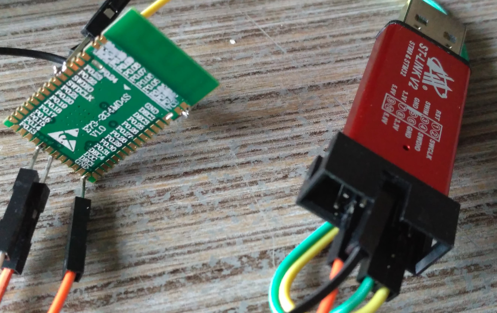
    For uploading code onto the Ebyte modules I use an ST-Link V2 (2 dollar USB modules).

    • Install the USB-Driver using Zadig

    • Connect the DIO, CLK VCC, and GND.
      For testing purposes, I soldered just the tips of some Dupont cables to the Ebyte module and put the female parts on the ST-link.

    • The first time I want to upload code, I first "burn the bootloader" (Tools => burn Bootloader) (https://forum.mysensors.org/topic/6961/nrf5-bluetooth-action/386)
      This will give an error.
      After that, you should be able to upload sketches.

    0_1525087406964_IMG_20180430_131940.jpg


  • Hardware Contributor

    @omemanti said in nRF5 Bluetooth action!:

    That's what I suggested earlier but it seems it didn't work. But I don't remember if it was with an stlink.


  • @alowhum
    maybe a very stupid question, but did you check all the wires and after that if your computer uses the right drivers.

    I took me quite a while to figure this out myself. Especially the driver part messes things up. Errors everywhere that referred to different problems, but after I used Zadig they all disappeared.


  • Hero Member

    @mars-warrior said in nRF5 Bluetooth action!:

    @Omemanti and @NeverDie are using these modules, so should be able to write something up that works for other ppl

    As I've said many times previoiusly, I use the nRF52 DK to program external modules, and it's what I recommend for noobs because it's relatively hassle free. If you're able to use the $2 st-link v2 programmer then great, my hat's off to you. If not, I recommend the nRF52 DK rather than get frustrated and give up.


  • Plugin Developer

    @neverdie said in nRF5 Bluetooth action!:

    nRF52 DK

    Which hardware programmer do you use with that?

    I find many of these software packages, like Segger's JLink stuff, are made for Windows (I'm on a mac).


  • Mod

    @alowhum you can still install windows on it ๐Ÿ˜…


  • @alowhum by programmer you mean in something like the Arduino ide? That's what I use ( I both use the nrf52dk =>j-link aswell the st-link v2 => st-link)


  • Plugin Developer

    @Omemanti I didn't realise the nRF52-DK was a hardware device. I thought it was a software program.

    On the picture you provided (thanks!), are pin 6 and 8 connected to a serial port to read what's going on? Your ground is connected in a different place than mine (I connect it next to the VCC pin). I suspect both those side-pins near the antenna, at the top, where you have soldered something, are ground too, right?


  • @alowhum said in nRF5 Bluetooth action!:

    @Omemanti I didn't realise the nRF52-DK was a hardware device. I thought it was a software program.

    The nrf52 dev kit= > NRF52 Dev kit

    To connect the DK to a module :
    DK Ebyte module
    GND(detect) => GND
    SWDIO => SWDIO
    SWDCLK => SWCLK
    VTG => 3,3V
    3,3V => 3,3V
    GND =>GND

    select J-link and there you go.

    On the picture you provided (thanks!), are pin 6 and 8 connected to a serial port to read what's going on?

    I used Pin 6 and 8 to connect to a FTDI to read out the serial. Since you can tell the sketch where to put the RX and TX I just connected them to 6 & 8.

    Your ground is connected in a different place than mine (I connect it next to the VCC pin).

    the Ebyte module has multiple GND connections, I messed the one next to the VCC up so I connected them next to the antenna. Just because I was easy ๐Ÿ˜‰

    I suspect both those side-pins near the antenna, at the top, where you have soldered something, are ground too, right?

    Indeed!


  • Plugin Developer

    JLinkExe gives me this:


    WARNING: RESET (pin 15) high, but should be low. Please check target hardware.


    I already had some signs these EByte modules have a reset issue. As it they are constantly being reset. This points to that again. hmm.


  • @alowhum

    Hey, sorry, I'm not familiar with your error messages.

    Can you please sum everything up what you did so far and what your setup looks like (pic)

    • Drivers
    • Libraries
    • what software you use
    • Number of modules you tested
    • etc

    just to retrace your steps ( It might be useful to post it in a separate topic to keep this one cleaner ) => https://forum.mysensors.org/category/5/troubleshooting


  • Hardware Contributor

    For those interested, NRF52840 is already available on AliExpress from HolyIOT, it's the revision 1 of the chip, too bad they put a chip antenna ๐Ÿ˜ž

    https://www.aliexpress.com/store/product/Nordic-nRF52840-Bluetooth-module-grid-development-board-BLE5-0-Bluetooth-serial-low-power-voice-long-distance/420533_32868365660.html

    [Edit] They also have the most compact NRF24 compatible gateway ever, for 10$ ๐Ÿ˜ฎ
    https://www.aliexpress.com/store/product/Nordic-nRF52832-BLE-4-0-4-2-5-0-USB-UART-BLE-dongle-for-computer/420533_32862480389.html


  • Hero Member

    Looks as though there is also a new DK for the nRF52840 as well:
    https://www.digikey.com/product-detail/en/nordic-semiconductor-asa/NRF52840-DK/1490-1072-ND/8593726
    just not in stock.

    Looks like HolyIOT is ahead of the curve on this chip.


  • Plugin Developer


  • Hardware Contributor

    @alowhum said in nRF5 Bluetooth action!:

    @nca78 said in nRF5 Bluetooth action!:

    https://www.aliexpress.com/store/product/Nordic-nRF52832-BLE-4-0-4-2-5-0-USB-UART-BLE-dongle-for-computer/420533_32862480389.html

    Cool!

    If you buy one, buy the "black" version, it's a bit bigger but it's because it has a PCB antenna, range will be better.


  • @nca78 I don't recognize any LDO on the PCB while it has USB power supply. How is 5V converted to 3.3v?


  • Plugin Developer

    @toyman said in nRF5 Bluetooth action!:

    @nca78 I don't recognize any LDO on the PCB while it has USB power supply. How is 5V converted to 3.3v?

    I was wondering the exact same thing!


  • Hardware Contributor

    small internal dcdc converter


  • Hardware Contributor

    @alowhum said in nRF5 Bluetooth action!:

    @toyman said in nRF5 Bluetooth action!:

    @nca78 I don't recognize any LDO on the PCB while it has USB power supply. How is 5V converted to 3.3v?

    I was wondering the exact same thing!

    Look at bottom of page 6 and top left of "schematic" on page 9 of the CP2104 datasheet. It can supply up to 100mA.
    https://www.silabs.com/documents/public/data-sheets/cp2104.pdf


  • Hero Member

    Can someone please provide a link to the module being discussed? I tried looking on Aliexpress, and I don't see anything which matches.


  • Hardware Contributor


  • @nca78 Got it. So it's kinda Arduino Nano, but nrf52-based.


  • Hero Member

    @nca78 said in nRF5 Bluetooth action!:

    @neverdie it's this link, in the description on aliexpress you can see the internal PCB "module"
    https://www.digikey.com/product-detail/en/tag-connect-llc/TC2030-CLIP/TC2030-CLIP-ND/2605371

    ? Plug of nails?


  • Hero Member

    I dropped "Bluetooth" from the title of this thread because the thread instead evolved into the MySensors alternative to Bluetooth.


  • Plugin Developer

    How hard, or how much work, would it be to create a version of the MySensors gateway that works on one of those dongles?


  • @alowhum my understaning, it should work out of the box


  • Plugin Developer

    Really? So something like:

    • Upload gateway sketch to it (how?)
    • Select "serial connection" in Domoticz?

  • Hero Member

    @alowhum You'd still need a programmer


  • @neverdie ...and some nifty soldering skills in order to connect to SWDIO/SWDCLK pads


  • Hardware Contributor

    i don't think you need extraordinary soldering skills, pads on bottom looks easy ๐Ÿ˜‰ (pretty sure these are the programming pads)

    The right question, imho, would be: can you expect from this dongle the range you would expect from a gateway ?? regarding chip antenna performance and maybe its gnd counterpoise..


  • @scalz said in nRF5 action!:

    pretty sure these are the programming pads

    they are even "labeled" on the x-ray picture below


  • Hardware Contributor

    @Toyman yep, this confirms what i said, not difficult to access.
    I didn't read the description..just looking at the pcb layout was enough to tell me poor rf range + no basic usb spec design rules (latter point is maybe not the most critical for most of people, but it just shows 1) designer wasn't aware ?? 2) this is what you get for cheap money, whereas missing parts would have cost few cents..).
    Just saying, because maybe this dongle can work well enough for some people.


  • @scalz actually, it might be ideal as a REPEATER given the form-factor. You just insertt it into any cheap USB charger and voila.


  • Hardware Contributor

    @Toyman that's a valid point, sure. Here, I prefer to not have repeater as much as i can, else i switch to subghz ๐Ÿ˜‰


  • This post is deleted!

  • Hero Member

    @jokgi said in nRF5 action!:

    @neverdie I would suggest holding off on purchasing a new nRF52840-PDK until the final silicon is released.

    Oh! It's still not?


  • @scalz 0_1526314656566_nRF52840-dongle-smaller.jpg
    I would be interested in any range testing in regard to this dongle. For ground it has whatever it is that it is plugged into. (PC, SBC, USB extention cable, etc) There will be a nRF52840 based dongle out soon. See picture above. This dongle will need to be programed over the SWD lines. No Segger on board this one..!


  • Hardware Contributor

    @Jokgi i'm not using usb dongle but it looks nice. (too bad 52840 is AQFN..)


  • @Nca78 0_1527343061376_IMG_20180526_155051.jpg
    Getting rid of the ground plains around the entire module hugely improved the range. Had to stap back to AAA batteries to fit on the board. But I'm happy with the way it's going (AA is still possible but not soldered on it just doesn't fit enough in the wall socket)


  • Hero Member

    Very nice. Looks professional!


  • Very nice indeed. I thought ground plains improve the range


  • Hardware Contributor

    @toyman said in nRF5 action!:

    Very nice indeed. I thought ground plains improve the range

    He's talking about the ground plane around the nrf5 module, not on the full board ๐Ÿ˜‰


  • Mod

    @toyman they do, but not too close to the antenna ๐Ÿ˜€


  • Hardware Contributor

    What about moving the PID-related discussion to a dedicated thread as this one is already excessively long and useful information will get lost soon ?

    @neverdie said in nRF5 action!:

    It was very hard to extrude it, so I always seemed to either underextrude or overstrude. I found it very hard to get the right amount exactly where it should go by just manually pressing the plunger on the solder paste syringe that the material came in.

    Yes I had the same problem too... added with too old solder paste from my local shop ๐Ÿ˜ž
    I just ordered a stencil together with my test PCB, I guess it's the way to go given the now very low prices of stencils (mini-stencils at 9.9$ at Seeed and I just paid 7$ + 2$ PCB at JLCPCB, same company than EasyEDA).


  • Mod

    I think we should open a dedicated thread about smd


  • Hardware Contributor

    @gohan said in nRF5 action!:

    I think we should open a dedicated thread about smd

    We had the same idea at the same time.
    I moved the related posts here => https://forum.mysensors.org/topic/9412/smd-reflow-oven-pid

    Not sure the title is the best, feel free to suggest a better one in the other thread ๐Ÿ™‚


  • Hello guys. Finally I've got some nrf51288 boards, like used here: https://www.openhardware.io/view/510/Button-cell-Temperature-Humidity-sensor I've hooked it up to ST Link, uploaded test sketch and everything worked fine. Then I tried to put it to sleep and measure power consumption. The best number I'm getting is 550uA... And it seems like something is completely wrong with this. Either my readings, or some bug in new version of Mysensors library or nrf5 arduino core.
    To be sure it's not particular chip's bug I've checked both I've got, no differences. I've also checked current on stock BLE firmware from manufacturer it was running when they came. It was around 120uA - 200uA while presenting via bluetooth. So I guess it can't be that my readings are completely wrong. But then how can it be that bluetooth presenting consume less current than sleeping?
    For now I couldn't find a solution or any hint for this, so I apologize If I am missing something, but I need help.

    EDIT: I might just delete this post, but maybe someone will search for the same solution. Long story short 600uA extra is due to the lack of low frequency crystal onboard. It makes HFCLK to not shutdown and draws current during a sleep. I knew, that synth RTC will take more current but I didn't expect it to be that much.
    Another question is why sleep that depends on pin change and seems doesn't require RTC consumes 1ma? I'm confused...


  • To summarize, what I have for now.

    void setup() {
      NRF_GPIO->PIN_CNF[10] = ((uint32_t)GPIO_PIN_CNF_DIR_Input        << GPIO_PIN_CNF_DIR_Pos)
                              | ((uint32_t)GPIO_PIN_CNF_INPUT_Connect    << GPIO_PIN_CNF_INPUT_Pos)
                              | ((uint32_t)GPIO_PIN_CNF_PULL_Pullup      << GPIO_PIN_CNF_PULL_Pos)
                              | ((uint32_t)GPIO_PIN_CNF_DRIVE_S0S1       << GPIO_PIN_CNF_DRIVE_Pos)
                              | ((uint32_t)GPIO_PIN_CNF_SENSE_Low   << GPIO_PIN_CNF_SENSE_Pos);
      NRF_GPIOTE->INTENSET = GPIOTE_INTENSET_PORT_Msk;
      NVIC_EnableIRQ(GPIOTE_IRQn);
      delay(2000);
      NRF_RTC1->TASKS_STOP = 1;
    }
    
    void loop() {
      NRF_RADIO->TASKS_DISABLE = 1;
      NRF_CLOCK->TASKS_HFCLKSTOP = 1;
      __WFE();
      __SEV();
      __WFE();
    }
    
    void GPIOTE_IRQHandler(void)
    {
      // This handler will be run after wakeup from system ON (GPIO wakeup)
      if (NRF_GPIOTE->EVENTS_PORT)
      {
        NRF_GPIOTE->EVENTS_PORT = 0;
    
      }
    }
    

    While delay(2000); consumes 4mA, after stopping RTC and HFCLK and going to sleep as expected consumes less than 10uA (my meter can't read less than that so it shows just 0).

    • The same code adapted for use with mysensors library:
    #define MY_RADIO_NRF5_ESB
    
    #include <MySensors.h>
    
    void setup()
    {
      NRF_GPIO->PIN_CNF[10] = ((uint32_t)GPIO_PIN_CNF_DIR_Input        << GPIO_PIN_CNF_DIR_Pos)
                              | ((uint32_t)GPIO_PIN_CNF_INPUT_Connect    << GPIO_PIN_CNF_INPUT_Pos)
                              | ((uint32_t)GPIO_PIN_CNF_PULL_Pullup      << GPIO_PIN_CNF_PULL_Pos)
                              | ((uint32_t)GPIO_PIN_CNF_DRIVE_S0S1       << GPIO_PIN_CNF_DRIVE_Pos)
                              | ((uint32_t)GPIO_PIN_CNF_SENSE_Low   << GPIO_PIN_CNF_SENSE_Pos);
      NRF_GPIOTE->INTENSET = GPIOTE_INTENSET_PORT_Msk;
      NVIC_EnableIRQ(GPIOTE_IRQn);
    }
    
    void loop()
    {
      transportDisable();
      NRF_POWER->TASKS_LOWPWR = 1;
      NRF_RTC1->TASKS_STOP = 1;
      MY_HW_RTC->POWER = 0;
      MY_HW_RTC->INTENCLR = RTC_INTENSET_COMPARE0_Msk;
      MY_HW_RTC->EVTENCLR = RTC_EVTENSET_COMPARE0_Msk;
      NRF_ADC->TASKS_STOP = 1;
      NRF_ADC->ENABLE = 0;
      NRF_CLOCK->TASKS_HFCLKSTOP = 1;
      NRF_UART0->TASKS_STOPRX = 1;
      NRF_UART0->TASKS_STOPTX = 1;
      NRF_UART0->TASKS_SUSPEND = 1;
      __WFE();
      __SEV();
      __WFE();
    }
    
    void GPIOTE_IRQHandler(void)
    {
      // This handler will be run after wakeup from system ON (GPIO wakeup)
      if (NRF_GPIOTE->EVENTS_PORT)
      {
        NRF_GPIOTE->EVENTS_PORT = 0;
    
      }
    }
    

    I know that this code is wrong, as it doesn't enable peripherals after wake up, and it I just took chunks of code from different places trying to disable whatever is running by mysensors and consumes that extra current. So in sleep this code consumes 200-230uA.

    All is running on WT15822 board like this: 0_1532876534214_WT51822-S4AT.jpg
    It doesn't have 32KHz crystal, but I program it using "Crystal Oscillator" from board menu of nrf5 arduino core.
    As far as I understand some of the periferals and/or interrupts and/or timers is used by Mysensors stack and doesn't shut down when going to sleep, so it tries to use RTC, which is not available, so it wokes HFCLK, so it consumes extra current. A lot more than it should in sleep mode.

    I need help with this, as I am planning to build a bucnh of simple window sensors on this board and they doesn't require wake by timer, but will be woken by extrnal pin interrupt. But for now I just can't use Mysensors sleep function to do this, because as I have described it works not as expected. Hope to get some response from you guys.


  • Mod

    Great work @monte, thanks for sharing.

    Just to set your expectations correctly: Very few MySensors users have tried nrf5 so far, so the combined experience is quite low. Hopefully someone has an idea on how to help you, but it could very well be that you're the community's most experienced user in this area thanks to your work.


  • Hardware Contributor

    @monte thรฉ HFCLK is on because of a hardware bug in nrf51822 when you want to wake up using pin interrupt. You have to use PORT interrupt to go really low (around 5uA).

    I made some (dirty) test code to validate that with MySensors but there was not much interest in that in the forum so I switched to something else. I will not use nrf51822 but nrf52832/40, they became really cheap now and don't have this hardware bug.


  • Hero Member

    @nca78 By the way, were you ever able to get multiple different interrupts working?

    Here we are a year later, and I guess there's still no final silicon for the nRF52840?


  • Hardware Contributor

    @neverdie it works with the code I posted.

    There are a few modules available with nrf52840 now so I guess final silicon is out. But it's only available in WCSP format I think so you won't see the chip alone.


  • @nca78 The Rev C (COO) parts are available now and they are the production parts. (Symmetry and Nordic's other distributors have these in stock) There will be a respin of this to a Rev D to fix the REG0 issue. FYI, the current nRF52840 package is not a WCSP. It is a aQFNโ„ข package. The nRF52840-Dongle is also available now. Go forth and design......


  • @nca78 well, after 2 nights of intense trying and failing I've got code to work as expected. And yes, it works with PORT interrupt, its kinda more code for you to write in compare to simply using attachInterrupt function, but I'm okay with that. For me double the price of 52832 compared to 51822 is significant. And for now, for a simple sensor stuff as we do with mysensors I don't really see any advantages except that interrupt bug fixed.
    Also I've found that Mysensors sleep function for nrf5 is missing one very important command, I don't know why, maybe it is nrf51822 specific and thus @d00616 missed it but in current version of Mysensors library it doesn't disable UART before sleep, that's why I was getting 120-200uA current during sleep. I still don't really know how to make pull requests on github, so I guess I will just post it here:
    line 290 of MyHwNRF5.cpp should contain: NRF_UART0->ENABLE=0; and line 327: NRF_UART0->ENABLE=1; respectively. That completely disables UART on nrf51822.
    I will post my complete sketch later, when I will finish it, maybe someone who strugles as I did will find it useful. Also I think we need to somehow combine all examples that were posted in this thread or at least put a list of them with links, because looking through 1654 posts is not an easy task, especially if you not sure what you are looking for exactly.


  • @monte But you solve your issue with the WT15822 board? Can you please share your sketch?

    Is the range good of the WT15822 board?

    I have started sketching to create a couple of new simple temp / hum sensors (WT15822, si7021 and cr2032) and want to know if I can use WT15822 before I order a pcb ๐Ÿ™‚


  • @smilvert I think I solved issues I mentioned. But I don't have final code yet as I am waiting for parts to arrive for my board. But I think there is no problem using WT51822 board except that you'll have to manually set PORT interrupt and also set pin SENSE register which is cannot be done with arduino function pinMode().
    So I guess you can order PCBs if you want, I'm going to post final sketch with explanations at the end of the month.


  • Hey,

    I got an issue with getting my custom board with SI7021 under 450uA.

    • Ebyte 52832

    I use the Sparkfun library to read data from it

    I did some deductions.

    • When I insert sensor.begin(); it starts using quite an amount of power when sleeping.

    • When I remove this line it shoots down to around the 10ua.

    • I tried 2 board, that are identical, with exactly the same results

    This happens also when I use this code on a board that doesn't have a SI7021 soldered onto it. So I don't think it is the SI7021.
    SDA/SCL are both connected with a 10K pull-up.

    My guess is that is has something to do with it being a thing with the NRF.

    the readings from the SI7021 seem legit, so it works, but the sleep current wrecks my battery life.

    Is there someone that can help me with this?

    The same old story, when you finally go looking for help, you find your answer.
    It indeed looks like it has something to do with the NRF52.
    as mentioned: https://github.com/sandeepmistry/arduino-nRF5/issues/291#issuecomment-407492282

    A workaround for the symptoms is known and described at:
    http://infocenter.nordicsemi.com/index.jsp?topic=%2Fcom.nordic.infocenter.nrf52832.Rev1.errata%2Fanomaly_832_89.html&cp=2_2_1_0_1_26

    Solution:

    you need to add the following lines to shutdown the i2c:

    NRF_TWI1->ENABLE=TWI_ENABLE_ENABLE_Disabled << TWI_ENABLE_ENABLE_Pos;
    *(volatile uint32_t *)0x40004FFC = 0;
    *(volatile uint32_t *)0x40004FFC;
    *(volatile uint32_t *)0x40004FFC = 1;
    

    And when you need some readings, just call "sensor.begin(); " to go on your way.

    I measure 00.01 mA now, (multimeter doesnt go into the uA ranges ๐Ÿ™‚ )

    Maybe @d00616, or someone else can work this into a standard routine (this is way out of my league, i can dump it into my sketch, but dont have a clue what it is doing)


  • @omemanti It seems like some peripherals are not shut down before sleep. As library you've mentioned uses Wire library, it must be TWI (i2c) interface that are active during sleep and consumes extra power. I'm afraid that you will have to manually disable/enable TWI around sleep routine.
    EDIT: I see you've found an answer by yourself. Just want to clarify that it isn't nrf5 chip's fault, it just how it intended to work. It doesn't automagically disable all peripherals during sleep. So, someone should write low current sleep library for nrf5 specifically, that will check the state of peripherals before sleep and disable them if needed.


  • Hero Member

    Anyone played around with Nordic's nRF52840 dongle? They're $10 each, and a few places have them in stock.
    https://www.nordicsemi.com/eng/Products/nRF52840-Dongle

    Nordic finally has a v1.0 product specification for the nRF52840, not just the silly v0.5 that they had posted for so long. http://infocenter.nordicsemi.com/pdf/nRF52840_PS_v1.0.pdf

    It has 256K RAM and 1MB of flash. I'm having difficulty imagining which applications would require that much of either one. If it were free, that would be great, but I'm afraid the large RAM becomes an energy drain. For instance, it consumes 3.16ยตA with System ON, full 256 kB RAM retention, and wake on RTC.

    On the other hand, it consumes 0.4uA of current if System OFF, no RAM retention, and wake on reset

    It consumes 16.4ma if transmitting at full power (8dBm) with DC-DC engaged.

    If compared to LoRa, it's going to lose on range. However, the question is: will it be good enough in a large or otherwise difficult home environment? The specs say it should be better than either nRF24L01 and nRF52832, which seem better suited to smaller dwellings. Maybe (?) the question can be answered with a couple of dongles.


  • Hardware Contributor

    @neverdie I want to, but only shop that can send me with free shipping (and not 75$ like the others) is Arrow, and it's not yet in stock there.
    CDEByte sells some too now ... but with a small form factor & ceramic antenna, I'm afraid it will waste all the theoretical extra range...


Log in to reply
 

Suggested Topics

  • 8
  • 2
  • 2
  • 2
  • 90
  • 3

23
Online

11.2k
Users

11.1k
Topics

112.5k
Posts