CNC PCB milling
-
@neverdie If you go 6mm or 1/4 inch only to flatten the bed, you might be better off just selecting the collet after buying a plain router bit locally, probably neither will be used for much if anything until you need to replace the bed.... They are pretty cheap usually and ideal for mdf, just keep the cutting rate cautious with the light drive motor, and beware of the dust, it goes everywhere, and you can't spray it as water affects the mdf...
A 1/4" face cutter would put less load on your motor than a 1/2", just take it easy on the milling rate....
-
I'm not sure how to analyze it a priori. If I have to run it at a much lower feedrate to compensate for a light duty motor, then the supposed speed benefits of a larger end-mill might not materialize.
-
@neverdie said in CNC PCB milling:
a priori
? You mean as earlier, sorry, I didn't use Latin after 60BC, it rather went out of fashion don't you know....

The power you require to bring the mass up to speed is one thing, the speed of approach and the area to be cut is the greater puzzle I suggest. The bit will not snap for sure, your motor might object if you take big bites though...
If you rip the surface in a 0.5mm top slice and listen to the motor you will get a good idea of how it reacts, then either increase the approach speed or the depth I would suggest.. You are using the device outside it's parameters, better to be cautious, the bits are a lot tougher than the motor...
-
I ordered the collets and end-mills that I referenced above, so after they arrive I'll post an update as to how it went.
Meanwhile, now that my CNC is in the garage, it's hard to know when it has finished running. I'm thinking of making a node to monitor it and then sent me a wireless alert when it finishes. So, how best to know when it has finished? I'm presently toying with the idea of monitoring its current consumption, on the theory that if no significant current is flowing, then it is done. However, maybe someone here knows of a better way?
-
@neverdie I find it hard to believe you would just walk away from it with no curiosity or desire for direct observation. Have you considered using the highly technical door to access and use eyes to see and ears to listen ? You are breaking new ground here, or mdf actually, where is that American spirit? Did Galoka think the Ulus were too ugly to save?....
Beyond the giggles, I suggest a strategically placed vacuum cleaner intake as close as you can get taped down and just watch what happens, you are in a better position to cut power than 20m away diverted by Youtube....
-
@zboblamont
Watching it do an auto-level on 300 points is pretty boring.... I have better things to do than watch paint dry.
-
@neverdie Hey, your choice, your motor.....
Watching paint dry is most under-rated really, except when you are on the other end of the brush...
-
@neverdie why not put a webcam/ipcam at it, like many people do with a 3d printer?
Will show you when it's finished and when something goes wrong.
-
@zboblamont I think maybe you're misunderstanding. I would watch it do the bed-level (well, at the beginning anyway), to monitor drain on the motor. However, with all the auto-leveling and etching and milling and drilling I just let it run and come back when it's finished. That's really where I want to go with this in the end anyway. As far as protecting the motor, there should be (but maybe isn't?) something to shut it down if the current jumps above a certain limit. I should think that would be all the protection that's needed. So, maybe that's yet another reason to task an arduino with monitoring the current flow. One reason would be to alert me when the present job is done. The other reason would be to shut it all down if the current got too high (indicating a failure situation of some kind).
In fact, the beauty of having it in the garage is that it can run in the background without being noticed. If I were to run it in the house, the noise is rather overwhelming, and it would be hard to ignore it.
-
@yveaux said in CNC PCB milling:
@neverdie why not put a webcam/ipcam at it, like many people do with a 3d printer?
Will show you when it's finished and when something goes wrong.I just don't see the allure in that. It requires my polling it, rather than being interrupt driven. To me it's like putting a webcam on your dryer to observe when it's done. I mean, yes, it is faster than walking over to it, but it just seems far from optimal.
-
So, anyhow, maybe another way to check for job completion would be to monitor the DATA+ line from the USB cable feeding the WoodPecker controller. I'm guessing that if it shows no activity, then the job is done.
-
Is there something like, or does octoprint work with CNC machines? That might be an option if it does. Octoprint can monitor with an attached USB webcam
-
Yesterday I was doing copper removal with a 2mm end-mill, and several times when plunging it brought the motor to a complete stop. The motor recovered and continued in the x-y dimension at the new z.
So, obviously, the z-feedrate was too high. Is there a feedrate specific to the z-axis, or is it just the same as the general feedrate used by the x-y? I know there are velocity and acceleration parameters that can be different for x,y, and z. Do I control it using that instead of the seemingly general purpose "feedrate"?
Also, not sure why I experienced the problem this time and not previous times, as I was running the same g-code as before. Perhaps the end-mill acquired too much plastic gunk clinging to it? What's the best way to clean that stuff off?
-
@neverdie said in CNC PCB milling:
Is there a feedrate specific to the z-axis, or is it just the same as the general feedrate used by the x-y?
I ran some tests and proved that the general feedrate does apply to the z-axis. However, at the moment, the rest of the answer remains unknown to me.
-
@neverdie said in CNC PCB milling:
So, anyhow, maybe another way to check for job completion would be to monitor the DATA+ line from the USB cable feeding the WoodPecker controller. I'm guessing that if it shows no activity, then the job is done.
I tested this, and it won't work. It seems that USB is constantly sending data frames (or something) regardless of whether actual serial data is being transmitted.
So, to take the idea any further, I'd have to tap into and monitor the Serial Rx pin on the Woodpecker atmega328p chip itself.
-
@neverdie just a thought
One is able to customise a program header and footer of GCode programs
Maybe you could use a “coolant off” and “coolant on” (M07, M08 and M09 if I remember correctly) to achieve your goal?
-
I tried measuring the current with an INA219, and wow, the current measures much higher than what my bench power supply had been telling me. Doing just auto-leveling consumes about 0.5a at 24v. Turning on the spindle and just carving air consumes over 1a at 24v. So, I'm guessing that actually routing PCB material (not just air) might well exceed the 2a limit of the INA219, at least in worst case scenarios where the bit may bind (or the feedrate too high) enough to slow the motor down.
So, I'll simply slam a couple more shunt resistors in parallel with it, and then it should be good for measuring up to 6 amps.
All this assumes that the Woodpecker contains a proper snubber diode, so that I don't get voltage spikes when turning the spindle off. Indeed, it looks as though the woodpecker does have an SS54 schottky diode installed just below the spindle power plug, and I'm guessing it is intended to serve that purpose.
-
Virtually every screw on this CNC has come lose, so I'll be applying Loctite on all of them to hopefully avoid a repeat in the future.
I think there will just inevitably be some amount of vibration during the milling process (which obviously gets worse if there are lose screws). So, beyond Loctiting everything, I wonder if it makes sense to also rest the whole thing on some vibration dampers such as:
https://www.amazon.com/Anti-walk-Silent-Feet-Anti-Vibration-Machines/dp/B00536VQE0/ref=sr_1_8?ie=UTF8&qid=1518798934&sr=8-8&keywords=vibration+laundryI mounted our clothes dryer on these particular feet, and they work fantastic, at least for that purpose. Maybe not the right choice for this CNC though.
In the case of 3D printers, I notice that the Prusa I3 Mk3 sits on rubber feet, presumably for a similar reason.Anyone found good vibration damping feet for their CNC?
-
@neverdie Crazy though it may sound, have you considered cheap engine/gearbox mounts (for vehicles) for the base frame onto some baseplate or U-mounts?
All excess energy in a machine has to be dissipated to maintain base accuracy, the more rigid the structure is, the more that undamped energy is transferred to somewhere to dissipate, the base is probably the easiest to resolve...
-
@zboblamont
Not sure how that would be setup exactly.I'll try this:
https://www.amazon.com/dp/B00B84FNBS/ref=cm_sw_r_cp_ep_dp_H.1HAbVV7GBAFThat way the aluminum frame will be supported all the way around.
-
Here is the Sorbothane installed:
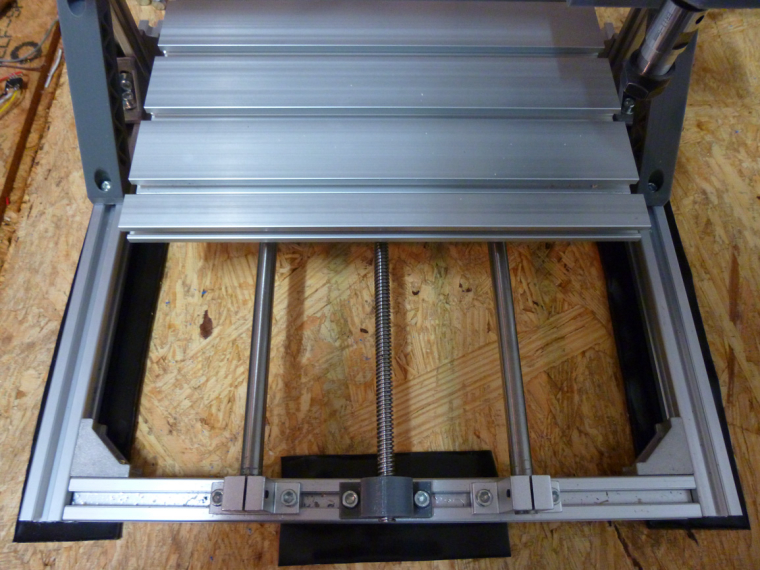
-
@neverdie Out of curiosity, I thought most CNC machines used ball screws. That to me looks like a lead screw.
-
@dbemowsk Yes, it's not a ball screw.
-
@neverdie Good, then I don't feel so bad using plain 5/16 threaded rods in my build. I would assume that there is some sort of anti backlash where it connects to the carriage though, correct? There is not a lot of play in mine to begin with, but I am using two threaded rod coupler nuts with a spring in between on mine to take up any little bit of backlash it might have.
-
@dbemowsk said in CNC PCB milling:
I am using two threaded rod coupler nuts with a spring in between on mine to take up any little bit of backlash it might have.
Yes, mine has a similar spring, and I assume for the same reason.
-
For now, I've settled on this hardware for monitoring the CNC when I'm not in the garage:
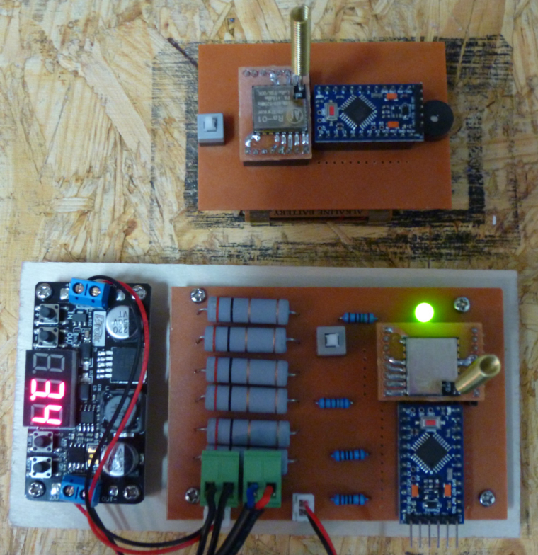
The bottom unit monitors the current that the CNC consumes to determine whether or not the CNC is active. When the CNC transitions from active to inactive, it sends a wireless signal to the battery powered node (above it in the photo), which rings a buzzer to let me know that the CNC has finished.Since my 3D printer that's on order is also 24 volts, I think there's a good chance this hardware may work with it as well.

-
The sorbathane helped a little, maybe, but there's still a lot of vibration. Found this video on how to dampen a 3D printer. It has some Interesting ideas on how to dampen vibrations:
Silencing the Prusa i3 MK2 & Horrible Vibrations – 05:13
— CNC KitchenThe video is aimed at Mk3 i2 owners, but I imagine similar tricks might work for a small CNC such as that discussed on this thread.
-
Based on a file test, it appears that the smooth rod is not hardened. Not sure how much improvement I might see if I upgraded to hardened.
Unfortunately, this thread seems to have fizzled out....
-
Looks as though upgrading to hardened and chromed rods is fairly inexpensive:
So, less sagging in the middle, and maybe less vibration also.
-
@neverdie As part of my CNC build, I have gotten 8mm rods that I pulled out of old scanners and old ink jet printers, I guess I never checked to see if they were hardened or not. How much of a difference would it make?
-
@dbemowsk Well, let's put it this way: the set screws on my rods had come lose, so I noticed considerable sagging when the spindle got to the middle of the rods. When I tightened up the set screws, a lot of that sagging went away. So, I think that means the spindle is now, in part, being supported by tension.
Hardened rods should flex less. I'm sure there are formulas that could tell you by how much. Also, there are different degrees of hardness.
-
On the other hand, according to this thread:
http://forums.reprap.org/read.php?1,113177
deflection isn't affected by hardness. I had thought hardened would be stiffer.
-
@neverdie So I have a few questions regarding your spindle assembly. First, do you know how many RPMs your motor is? Next, how many collets do you have and use for your setup. Third, is your collet and chuck assembly like this one?
https://www.amazon.com/Adealink-Spring-Collets-Extension-Holder/dp/B078JQQ5X7/ref=sr_1_2?s=hi&ie=UTF8&qid=1519193790&sr=1-2&keywords=5mm+shaft+collet
-
@dbemowsk said in CNC PCB milling:
@neverdie So I have a few questions regarding your spindle assembly. First, do you know how many RPMs your motor is?
I don't know. You could try asking the seller: https://www.aliexpress.com/store/product/Freeshipping-spindle-775-with-ER11-High-speed-Large-torque-DC-motor-Electric-tool-Electric-machinery-12/424291_32809235881.html?spm=2114.12010612.0.0.47291db35wj5jd
Next, how many collets do you have and use for your setup.
One.
Third, is your collet and chuck assembly like this one?
https://www.amazon.com/Adealink-Spring-Collets-Extension-Holder/dp/B078JQQ5X7/ref=sr_1_2?s=hi&ie=UTF8&qid=1519193790&sr=1-2&keywords=5mm+shaft+colletYour link says its an ER11A, whereas I think mine may be just an ER11.
Though my spindle eventually gets the job done, I think a more powerful spindle could maybe cut faster
-
@neverdie said in CNC PCB milling:
I don't know. You could try asking the seller
Thanks, I wasn't sure if you bought yours as a package deal where they had the specs on all the parts.
Your link says its an ER11A, whereas I think mine may be just an ER11.
I did find this link (http://www.cnczone.com/forums/cnc-tooling/319670-er11-type-vs-b-type.html) which states that the A should designate the style of the clamping nut. Looking at the different styles they have, it just looks like they just use different tools to tighten the nut. A looks like a standard wrench type.
This is the only information I have on the motor that I plan on using. I googled all the numbers and couldn't find anything.
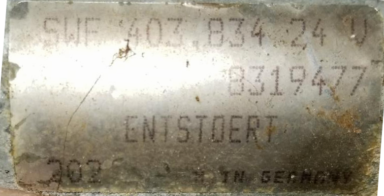
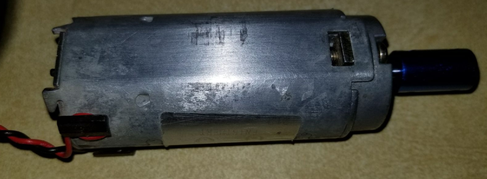
It is a German made motor, so I am assuming it is a pretty good motor. It feels like it has pretty good torque. It is one that I had in my junk parts bin. it has a 5mm D type shaft. In the pic I just have one of my 5mm to 8mm couplers on it. I think I may order that collet assembly as it sounds like it should work. It says that it uses ER11 collets anyway.
-
@dbemowsk Maybe you'll want to try using TMC2130 drivers for your stepper motors?
-
@neverdie I do already have the DRV8825's that came with the controller. I guess I'll try them and see how they work and if they don't seem to do well, I'll consider changing.
-
As it turns out, the smooth rods on my CNC are 10mm in diameter, not the more common 8mm found on 3D printers. Definitely not hardened: I can see grooves where the ball bearings have scratched into it.
Sanladerer strongly recommends using precision tolerance hardened chromed rods for 3D printers, so I can only assume the same would apply to CNC.
Since it's a relatively cheap upgrade, I may do it.
What tolerance should I get? h6? Also, what spec for surface roughness?
-
@neverdie said in CNC PCB milling:
Definitely not hardened: I can see grooves where the ball bearings have scratched into it.
Since it's a relatively cheap upgrade, I may do it.What tolerance should I get? h6? Also, what spec for surface roughness?
not surprised it is not hardened for the price, cheap price->cheap quality
pity is sometimes even more expensive kits cheat on this too..I would say as long as you use h6/h7 with roughness around 60 or more, so, precision hardened, chromed nice too, you should be very fine. day&night vs cheap rods which, in first place are not made for this job+precision..
-
I made some enhancements to the remote used with the CNC Monitor. Among other things, it's now more compact, and the top now has a ground plane (which may help the RF):
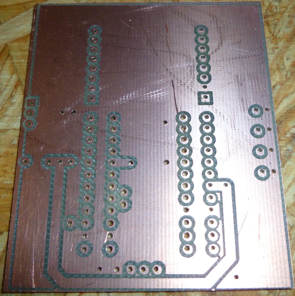
The bottom makes most of the connections and will hold the two AA batteries:
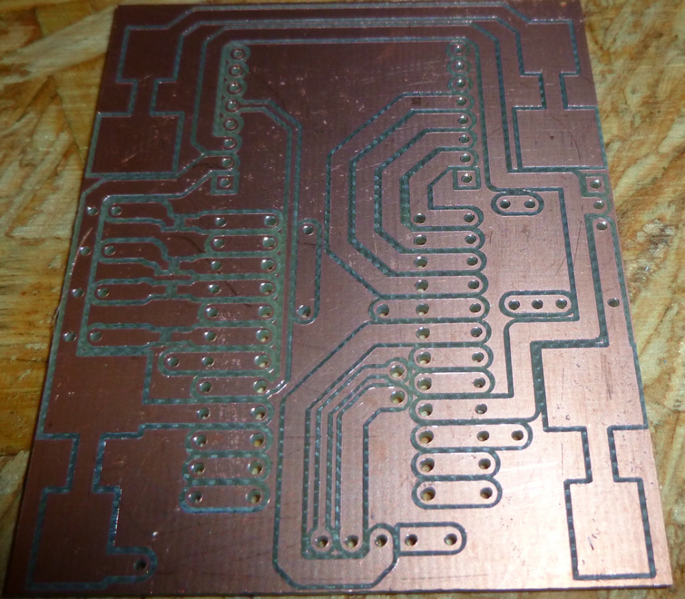
-
@neverdie So I have an odd CNC related couple of questions. Next, when you put a bit in the chuck, do you always bury it in to the base of the bit? When you have your bit in for working on PCBs, what is the distance from the end of the chuck to the tip of the bit that you use?
-
@dbemowsk Is this for calculating deflection?
-
@dbemowsk I haven't been very consistent, but I'd say roughly 7/8 inch.
-
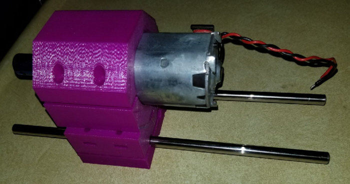
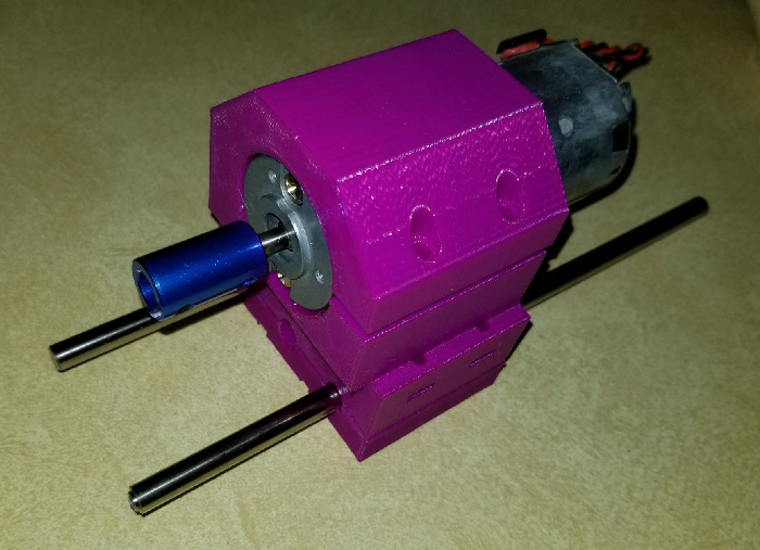
@neverdie Actually, I am working on my Z axis and am trying to gauge how long I should have my rods. They are currently 8.25 in (209.55 mm). Wondering if there would be any benefit to leaving them that long or shortening them up some more.
This is the spindle frame as I have it designed so far. The blue piece on the motor shaft is just one of the couplers that I bought for the steppers to connect the threaded rods. It is just for looks until I get the chuck.
-
@dbemowsk said in CNC PCB milling:
@neverdie Actually, I am working on my Z axis and am trying to gauge how long I should have my rods. They are currently 8.25 in (209.55 mm). Wondering if there would be any benefit to leaving them that long or shortening them up some more.
In that case, what matters is whether you can raise the spindle high enough on the z-axis to remove the used bit and insert the next one. I wish my z-axis had a bit more height on it. Sometimes I have to move the spindle away from the workpiece in order to get enough clearance for a tool change. I suppose it doesn't help that I'm using a 3/4" waste board.

-
@neverdie said in CNC PCB milling:
I suppose it doesn't help that I'm using a 3/4" waste board.
Do you need 3/4"? Wouldn't 1/4" or 1/2" work? Do you drill in that far?
-
@dbemowsk 1/2" is probably ideal for my particular setup. 3/4" is simply what I tried first. 1/4" might work, but with less margin for error.
-
@dbemowsk Shouldn't you have some linear ball bearings gripping those z-axis rods?
-
Here is the above PCB after assembly:
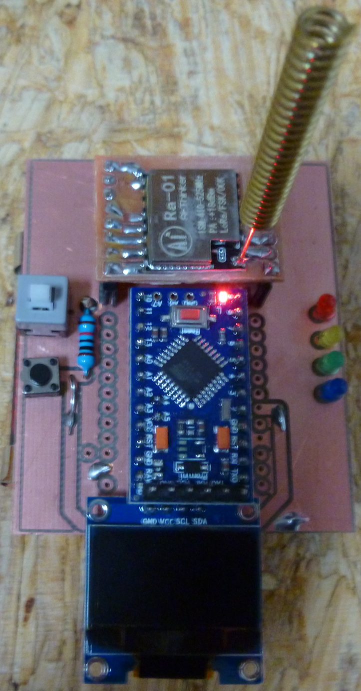
As you can see, it offers more potential functionality than the earlier version. It still has a buzzer, which is now mounted underneath the pro mini.
-
@neverdie FOr starters I am trying 3D printed rod bearings. I';ll see how that goes. The beauty of designing this myself is that I can alter the design whenever I want.
-
@neverdie Di the relocation of the buzzer increase audibility as you were seeking?
-
@dbemowsk said in CNC PCB milling:
I am trying 3D printed rod bearings
What are those? Is it like this?
or this?
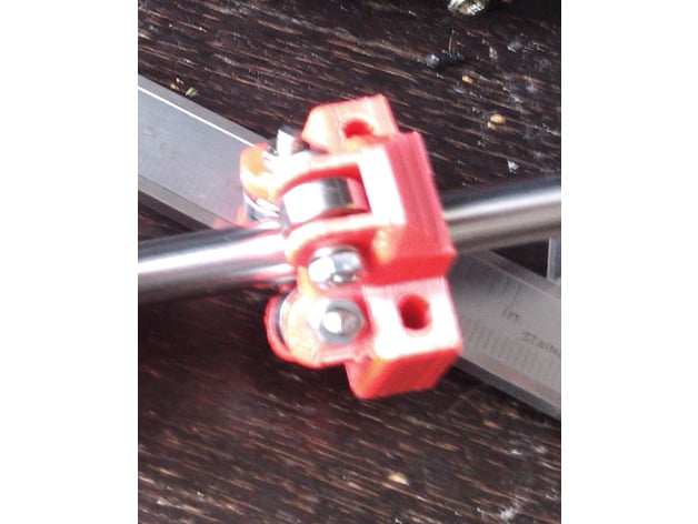
-
@neverdie
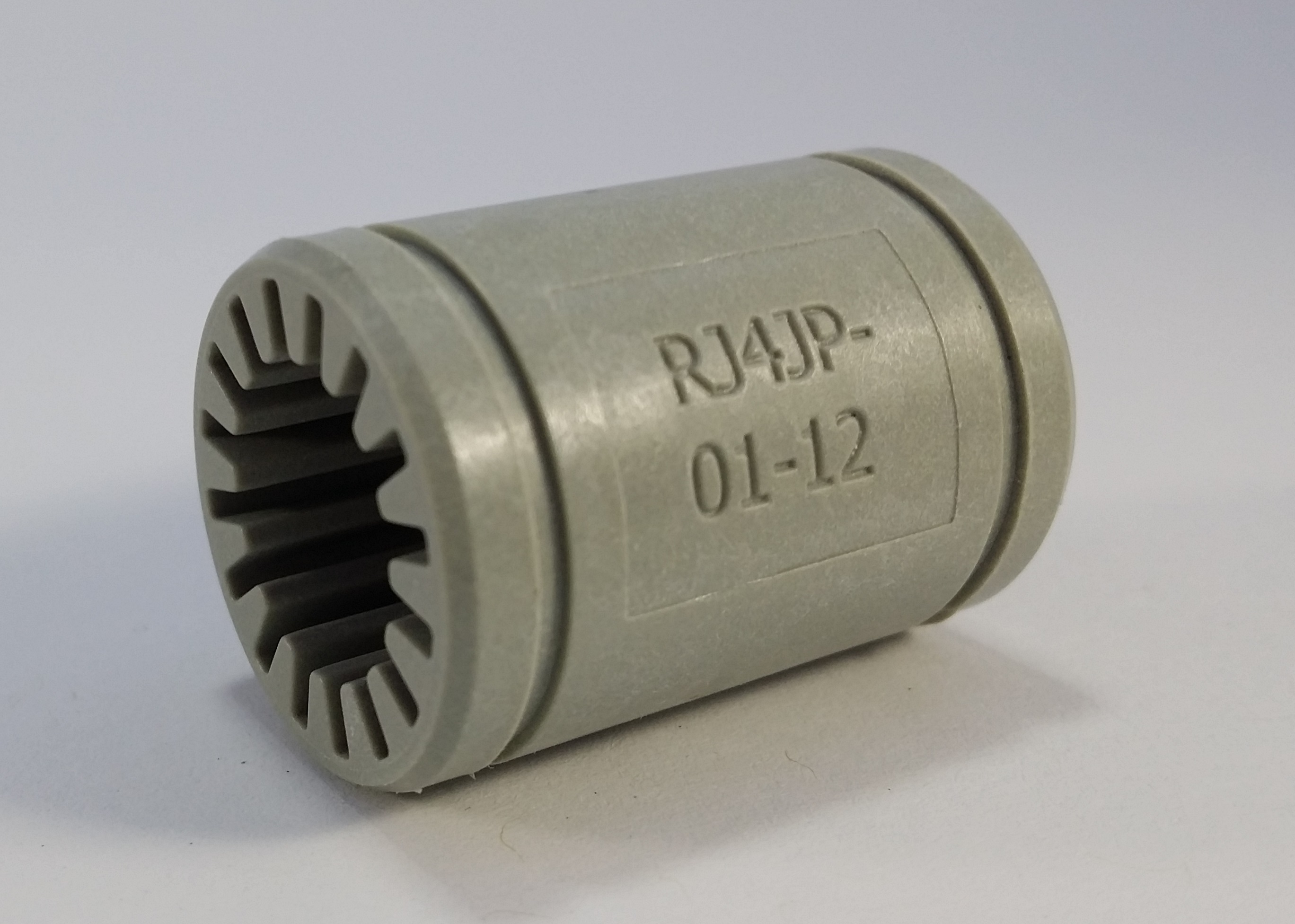 mine are similar 3D printed ones
-
@dbemowsk what kind of material?
-
@neverdie I just printed them in PLA and they seem to slide pretty smoothly on the rods, but someone told me that printing them in nylon is better.
-
@dbemowsk said in CNC PCB milling:
printing them in nylon is better.
It would seem so: http://www.craftechind.com/top-5-materials-for-plastic-bearings-used-on-metal-surfaces/
If you had a multi-filament printer, I wonder if you could print the nylon bearing within another plastic piece (e.g. the part that holds the spindle to the z-axis)? That would would be pretty cool and would also save assembly time.
-
@neverdie the way i have it designed, the printed bearings get sandwiched by a rear plate that holds the bearings and coupler nut that goes on the threaded rod to drive the assembly up and down.
-
I wasn't home before to get a pic, but here is the layout.
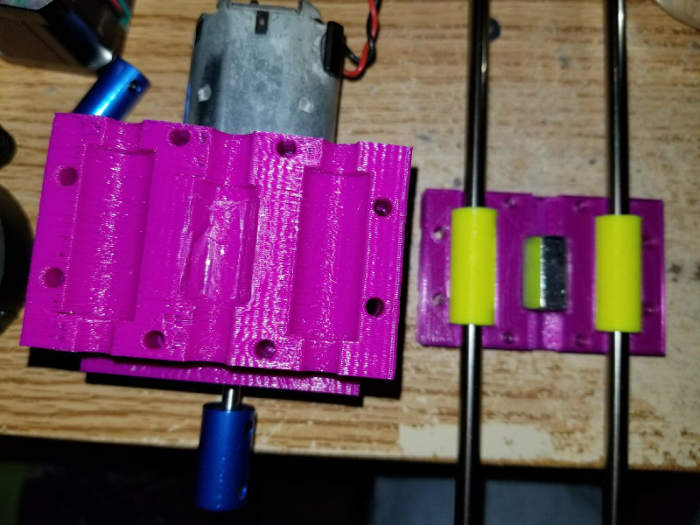
-
Anyone tried Trinamic drivers, such as the TMC2130? They seem to produce superior 3D prints, and so I would guess they would yield some improvement for CNC as well.
So far I've only found two boards that appear to be made for them, a ramps and a rumba:
https://www.aliexpress.com/item/MKS-Gen-V1-4-control-board-5PCS-TMC2130-V1-0-And-Heatsink-stepper-motor-compatible-with/32836389832.html?spm=2114.search0204.3.2.3e5a8105IWdaWH&ws_ab_test=searchweb0_0,searchweb201602_5_10152_5711320_10151_10065_10344_10068_10130_10324_10342_10547_10325_10343_10546_10340_10548_10341_10545_10084_10083_10618_10630_10307_5711220_5722320_10313_10059_10534_100031_10103_10627_10626_10624_10623_10622_10621_10620_10142,searchweb201603_2,ppcSwitch_5_ppcChannel&algo_expid=875aa997-05fe-4eda-9d76-0aaefcaeff83-0&algo_pvid=875aa997-05fe-4eda-9d76-0aaefcaeff83&priceBeautifyAB=0I have no experience with either board, so I don't know if either would be desirable.
The pinout of the TMC2130 is different than the A4988 driver currently used in my Woodpecker. However, I could perhaps make an adapter board to re-route the pins so as to be compatible. In that case, maybe I could plug them into my Woodpecker board. A video by Sanladerer seems to imply that might actually work:
How to make your 3D printer smart and silent with the TMC2130! – 17:02
— Made with Layers (Thomas Sanladerer)Note: from what I've read, the v1.1 TMC2130 modules are much better for adapting than the v1.0 modules.
-
I'm unsure what kind of firmware runs on the Woodpecker board, so I have doubts whether it could exploit the Trinamic features. Anyone here know?
So.... I'm looking at a Smoothieboard as perhaps one possibility, although I'm not sure yet as to whether Chillipepr will talkto it.
https://www.panucatt.com/azteeg_X5_mini_reprap_3d_printer_controller_p/ax5mini.htm
-
Are you looking at this for a 3D printer or for your CNC? If you are looking at it for a 3D printer, have you looked at the RAMPS 1.4 boards? I like their modular design over a fully integrated board for the simple fact that if a part dies, you are only replacing the one part and not an entire board. This make repairs cheaper if something goes wrong.
-
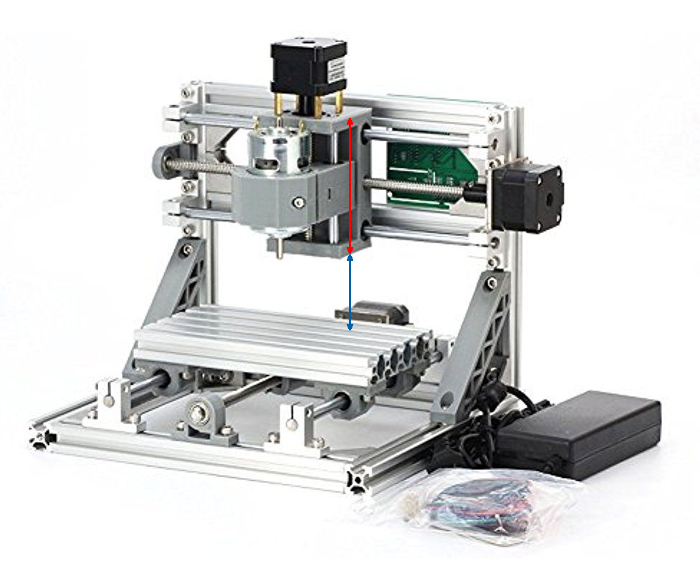
@NeverDie I have one more question of measurements on your CNC. If you look at the pic, can you tell me the measurements of the red and blue arrows on your machine? I have some idea of how tall I want my bracket for the red arrow area, but you were mentioning that you wish you had more travel in that area and I am curious if I have enough room.
-
@dbemowsk
red: 100mm
blue: 53mm
-
Perhaps slightly off topic but I wanted to share very interesting youtube channel of FRANK from Germany link text who's been working on a PCB pick and place module along with a CNC tool changer in the video above.
Very inginious, and clever work if you've not come accross his videos and work yet.!
-
@rfm69 said in CNC PCB milling:
PCB pick and place module along with a CNC tool changer in the video above.
Imho, it's certainly a fun project.. but I think you can go faster by hand

Only a thousands more expensive machine will be faster for assembling, and they are more precise, have a lot more features (cam driven features, more feeders etc.).Pick And Place is not plug and play at all
 there is lot of calibration, preparation. So it's useful and save time, only if you plan volume production. This is why there is often fees when you ask for a pcba, they spend time for calibrating each new board, parts in database etc.
There are multiple different diy pnp, most of them are slow, not enough precise for <0402 etc..
If it's for 0603 size with some dfn, low volume, you don't need this kind of investments I think.. but if you want to tinker it's fun I imagine.For example, if I remember well, someone said he can assemble an easypcb in 30mn, trhough hole. Good but that's the time I need to get assembled&soldered one of my compact smd multisensors boards, no PNP, no handsoldering..
PNP is just for placing, it won't fix test, soldering shorts etc, that still need some agility
No need of a solder paster dispenser, I use stencils. I like freedom for placing parts, but you can also build a simple manual pick&place in case you shake when placing (no shaking here). With a good magnifier, easy! (I have a big one like dentists, + another one with a cam). Finally, the reflow oven cook it. When I need a repair/reflow -> flux + hot air or fine solder tip. Well organized, you're faster like that. Not the same, if you want to assemble 50 boards, agreed.
So, I've no real xp on PNP, but I'm not new at assembling smd boards. Saying this because I already digged in forums, diy builds, reviews, as I need to invest in a cnc router, and PNP this year. and I'm lucky I can talk with local professionals.. I always "try" to get a good ratio between the need/time/ROI . I'll build the cnc router, but I'll buy the PNP. there are a few interesting but it's still a few thousands dollars.
-
@rfm69 Thanks! I've already learned something potentially very useful: instead of doing his etching with an etching bit, he uses a V spiral endmill 30 degrees. Unfortunately, he didn't say the diameter.

Interestingly, he didn't even bother with autoleveling.
How to mill a PCB with Chilipeppr s01e02 – 05:34
— Frank Herrmann
-
@rfm69 Yes, a tool changer would be very nice to have.
-
@neverdie said in CNC PCB milling:
Interestingly, he didn't even bother with autoleveling
Are you sure? What's happening from 3:25 then?
-
@yveaux said in CNC PCB milling:
@neverdie said in CNC PCB milling:
Interestingly, he didn't even bother with autoleveling
Are you sure? What's happening from 3:25 then?
You're right. I guess he edited most of it out, or else he did just a partial.
-
Looks as though StepCraft makes a tool changer that you can buy:
Cool Feature! - STEPCRAFT Automatic Tool Changer's Auto Tool Touch Off – 04:29
— Stepcraft Inc
-
@scalz Agreed... the P&P is beyond my knowledge level, but what I found fascinating in what and how he was doing the project to make something himself, how he evolved the project was very interesting.
He's got something similar for a tool changer on a 3d printer which is very nicely designed... along with the software and controllers.
-
@neverdie I saw this stepcraft automatic tool changer, its nice, but the design aproach of Franks is really novel, and way cheapper, simple ingenious. But my skill level is much lower, so I could be wrong

-
@rfm69 Does he describe in detail somewhere how to make one? I mean, I get the concept, but he did a lot of work on both the hardware and the software to make it functional.
-
@neverdie you mean the tool changer, yes he has a blog and git pages where he shares. Its neccessary to speed control with current limiting breaking the spindle, which he's done via cheap ebay motor controller and arduino. Same goes for the spindle locking mechanism powered by a servo. and the CNC software..
Heres the git link text
Heres the blog link text
Its not step by step, perhaps he'll get their but I know he'll be happy if people copy, or chime in :), or add
-
I noticed that Frank is apparently using carbon fiber tubing on his 3D printer. It turns out that carbon fiber tubing is an easy upgrade, if what you have already is aluminum rod:
New 3D Printer - Build Log #16 – 19:14
— Tech2CHowever, its Young's modulus appears to be about 10% less than steel, which I interpret to mean that it is a bit less rigid than steel (cf https://www.christinedemerchant.com/youngmodulus.html).
For the printer in the video that I linked, I can see how reduced weight may be worth the tradeoff.
However, since weight isn't really much of a factor in the 2418 CNC, I think it makes sense to stick with hardened steel rods.
Am I missing something? Opinions?
-
@andrew Hy my name is Ferenc please help me.
i update the grbl cnc 2418 firmware but dont read settings.
From where I can download it and how I can write it ?
My machine does not function properly now unfortunately. Please help thank you.
-
I'm noticing that the tips on 0.1mm etching bits last well enough if the PCB substrate if bakelite, but not very long at all if it's FR4. 0.2mm bit tips on FR4 seems to last much better.
-
@neverdie I'm gathering parts to make the same 3d printer with the carbon rods. I understood the weight reduction on the moving parts with carbon rods was the reason to go for them. And with the light 3d printer head that model can print much faster because of the stability and lightness. Which perhaps dosn't apply for the 2418 cnc ?
-
@neverdie Wall thickness as well as the material characteristics determine tube stiffness, comparison on the modulus alone is misleading.
As well as carrying the load, the section must also support it's own weight, one aspect where carbon fibre will out-perform steel.
-
What's the best way to check the RPM on my spindle? From looking at similar spindles on-line, I think it might be as low as 6000RPM at 24v.
So.... if I upgraded to a spindle that could go, say, 12000RPM, could I simply increase my feedrate by 2x and be done twice as fast?
-
@zboblamont said in CNC PCB milling:
@neverdie Wall thickness as well as the material characteristics determine tube stiffness, comparison on the modulus alone is misleading.
Granted. What's a better way to compare them based on the available info?
-
@neverdie Bluntly no idea whatsoever, I was merely highlighting the incorrect interpretation.
There is no magic bullet, that's why engineers are still in business, the analysis can be complex.
Were I looking at such a project it would to the lightest and stiffest complex alloy extrusions I would be focusing attention, and figuring out how best to combine them in a frame with minimal deformation.
Complex alloy extrusions are cheap sections with known quantified parameters and constraints, composites are relatively new, and their interconnections are less well understood than with conventional materials. unless you work for Lotus or Ferrari...
-
@NeverDie -- the motors used in 1610 CNC mills are generally what are called a "775 Motor". You might be able to find other specs, but the ones I've found suggest that at 24V and no load , they claim 7kRPM -- http://linksprite.com/wiki/index.php5?title=File:Motor_performance_parameter.png; I'm not sure how much slower we could expect it to be while milling. As far as actually measuring this, there are devices you could buy, but you could pretty easily fabricobble your way to an answer if you wanted to make a project out of it: http://www.instructables.com/id/Measure-RPM-DIY-Portable-Digital-Tachometer/.
I have the same mill as you, and swapped for one of these https://www.amazon.com/gp/product/B074FVKRZM/ and have had much better results so far.
-
@adam-coddington said in CNC PCB milling:
and have had much better results so far.
Any less vibration also?
-
I actually haven't had much trouble with vibration, so I can't really speak to that. The problems I've had have mostly been around runout, occasional arcing in the old spindle causing enough EMI to reset the microcontroller, Z-Axis backlash, the super-slow milling speeds necessary when spinning at such a low RPM, copper flakes everywhere, etc. Having the faster (and, maybe unfortunately, heavier) brushless spindle has been great for all of those things.
I happened to notice you looking into tool changers; if you're using bCNC, you might not have noticed the tool change workflow -- it's actually pretty elegant and will automatically re-zero your Z-Axis. It does require having a limit switch on at least the top of that axis, though. I used to hate tool changes given how tedious they were, but now they're pretty effortless.
-
Seems like most DC CNC spindles can do no more than 12,000RPM (if that). Which leads me to wonder: would replacing a spindle with a dremel be advisable? A dremel has an adjustable range of 5,000 to 35,000RPM.
Anyone tried this? Any downsides?
[Edit: I see that a number of the AC powered spindles can go as high as 24,000RPM. e.g.: https://www.aliexpress.com/item/1-5kw-Air-Cooled-Motor-cnc-Spindle-Motor-Spindle-110v-220v-ER11-CNC-Square-Milling-Machine/32850346694.html?spm=2114.search0104.3.53.6e8c5be0Uqy1Fs&ws_ab_test=searchweb0_0,searchweb201602_5_10152_5711320_10151_10065_10344_10068_10130_10324_10342_10547_10325_10343_10546_10340_10548_10341_10545_10084_10083_10618_10307_5711220_5722420_10313_10059_10534_100031_10103_10627_10626_10624_10623_10622_10621_10620,searchweb201603_25,ppcSwitch_5&algo_expid=42fb944e-06c3-4821-8a8b-3b49200ec2fd-8&algo_pvid=42fb944e-06c3-4821-8a8b-3b49200ec2fd&transAbTest=ae803_3&priceBeautifyAB=0
That sure would be interesting!
-
I suppose another factor worth considering is audible noise. Here's one that claims to be relatively quiet:
https://www.inventables.com/technologies/quiet-cut-spindleQuiet Cut Spindle Upgrade for the Shapeoko 2 (#28) – 09:15
— Winston MoyIt only goes to 12,000RPM, but I may be willing to trade speed for quiet. I can only assume that the 60000RPM unit isn't very quiet. Not at all sure how the brushless motor would compare. Possibly quieter?
-
I upgraded my CNC LoRa remote monitor into a more universal remote control by making it more compact and giving it 14 buttons:
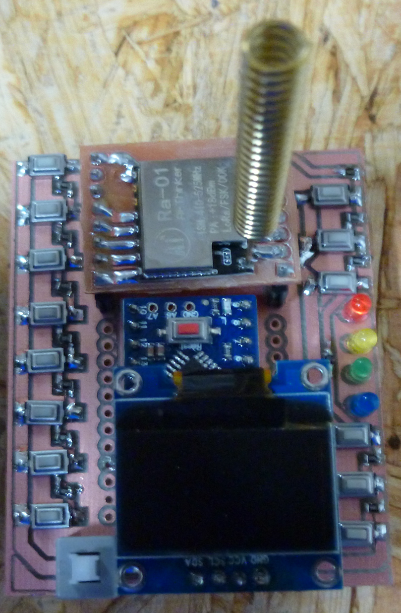
It turns out I can count the number of auto-leveling probes performed, in real time, because the total CNC current briefly drops to almost zero each time the probe makes contact with the PCB. Thus, this gives me a way of tracking auto-leveling progress remotely.

-
I went ahead and ordered this spindle upgrade, which looks as though it may be the same (?) as the Quiet Cut spindle.
https://www.aliexpress.com/item/BEST-300W-Mini-Spindle-motor-DC12-48V-ER11-12000rpm-Engraving-milling-grind-air-cooling-spindle-motor/32799767627.html?spm=a2g0s.13010208.99999999.262.sgcb5Q
-
I'm also looking for a good spindle so thanks for the links and comments.
Thought I'd share this link text. Its the 30A High Power Single way H-bridge DC Motor Driver Module. That "Frank From Germany" found and is using as part of his tool changing, along with a current sensor so he can brake, reverse and control speed on his tool changer, via arduino, to make it all work.
-
@coddingtonbear What materials are you milling ?
I want to get a spindle for mostly wood, just hobby, but don't want to go too cheap, and face buying over when I realize its just not > W
-
Just found a more powerful one...
@rfm69 link textSo could this or the 30A version, power an 800w DC 0-48V motor ?
-
800/48=16.7amp. Therefore, at least in terms of amps alone, the first (cheaper) one you posted should easily be sufficient, if you're running it just full-on or full-off.
-
@neverdie Thanks thats what I thought, but I'm confused about the voltage range of some of the spindles. They use variable DC voltage to regulate speed ? I don't thinks so, they use PWM at any voltage I provide it with, no ?
So the V range specified on DC spindle is just what it can be driven at, and its the PWM which actually controls the speed ? Is this right ?
Thanks
-
@rfm69 I believe so, at least for brush motors. For brushless, I get the impression the motors are missing the electronics which tell them when to alternate their currents internally, so (it appears) you need a special driver to make them move at all. I'm not sure how, or even if, PWM fits into that. Maybe motor speed is all managed entirely through the brushless controller, and all the brushless controller wants as input is pure DC?
-
@neverdie
 Now I'm even more confused with this difference between brushed and brushless...
-
@rfm69 The main advantages of brushless, as I understand it, are longer motor life (because no brushes to wear out) and probably less EMI if it's done right.
-
Also, I should think it would be easy for a brushless controller to provide accurate tachometer readings.
-
I'll probably get this to power my new spindle after it arrives:
https://www.amazon.com/gp/product/B0716XVR7P/ref=ox_sc_act_title_1?smid=AFHAE9RJVUMB&psc=1#customerReviewsInstead of PWM, I'll just adjust the voltage directly. Wish they could have given it a normal power plug for its AC input voltage....
-
In any case, I suspect that greater control over the speed of the spindle will lead to greater control over vibration as well. i.e. select a speed where there is less resonance/vibration of the pcb/spindle. Using an accelerometer to measure vibration, perhaps that could even be made somewhat automatic.
Alternatively, a trick I've seen used is to continuously vary the RPM over some range, so that the amount of time spent dwelling at the resonance frequency is reduced. That would also be easier to implement.
I imagine that either method might also lead to a generally quieter machine, which, IMHO, is generally desirable.