4CH AC LED Light Dimmer triack Module Leading Edge how to connect with Domoticz using MySensors?
-
Hi,
I'm planning to build controller for light based on Ardino Mega and Domoticz installed on Raspbery Pi 3 B. Somedays ago I 've bought Dimmer for light like here: e-bay dimmer and I'm looking for someone who can help me adopt scetch posted below to control dimming by Domoticz. I am using USB cable ror connection between Arduino and Raspberry at this moment.
Any help appreciated// Testing sketch for 50Hz !!! // / // Dimmer Arduino Mega // | | // GND GND // VCC 5V // SYNC DIGITAL.3 // CH1 DIGITAL.45 // CH2 DIGITAL.47 // CH3 DIGITAL.49 // CH4 DIGITAL.51 //https://github.com/mysensors/MySensorsArduinoExamples/blob/master/examples/RGB_3D/RGB_3D.ino #define MY_DEBUG // Enable debug prints to serial monitor //TO MUSI BYĆ ZDEFINIOWANE PRZED INCLUDE MYSENSORS #define MY_GATEWAY_SERIAL // Enable serial gateway #include <SPI.h> #include <MySensors.h> #include <TimerOne.h> // download this library from arduino.cc #include <Bounce2.h> unsigned char channel_1 = 45; // Output to Opto Triac pin, channel 1 unsigned char channel_2 = 47; // Output to Opto Triac pin, channel 2 unsigned char channel_3 = 49; // Output to Opto Triac pin, channel 3 unsigned char channel_4 = 51; // Output to Opto Triac pin, channel 4 unsigned int CH1, CH2, CH3, CH4; unsigned char i=0; unsigned int delay_time=2500; // delay ms or SPEED unsigned char clock_tick; // variable for Timer1 unsigned char Status_przycisk_1; unsigned char Status_przycisk_2; unsigned char Status_przycisk_3; unsigned char Status_przycisk_4; int16_t last_dim = 33; #define BUTTON_1_PIN 10 #define BUTTON_2_PIN 11 #define BUTTON_3_PIN 12 #define BUTTON_4_PIN 13 Bounce debouncer1 = Bounce(); Bounce debouncer2 = Bounce(); Bounce debouncer3 = Bounce(); Bounce debouncer4 = Bounce(); MyMessage Strefa_1_dimmerMsg(1, V_DIMMER); // Define message name and type to send sensor info MyMessage Strefa_2_dimmerMsg(2, V_DIMMER); MyMessage Strefa_3_dimmerMsg(3, V_DIMMER); MyMessage Strefa_4_dimmerMsg(4, V_DIMMER); void setup() { Serial.begin(9600); pinMode(channel_1, OUTPUT);// Set AC Load pin as output pinMode(channel_2, OUTPUT);// Set AC Load pin as output pinMode(channel_3, OUTPUT);// Set AC Load pin as output pinMode(channel_4, OUTPUT);// Set AC Load pin as output pinMode(BUTTON_1_PIN, INPUT_PULLUP); //przycisk kanał 1 pinMode(BUTTON_2_PIN, INPUT_PULLUP); //przycisk kanał 2 pinMode(BUTTON_3_PIN, INPUT_PULLUP); //przycisk kanał 3 pinMode(BUTTON_4_PIN, INPUT_PULLUP);//przycisk kanał 4 // After setting up the button, setup debouncer. debouncer1.attach(BUTTON_1_PIN); debouncer1.interval(5); debouncer2.attach(BUTTON_2_PIN); debouncer2.interval(5); debouncer3.attach(BUTTON_3_PIN); debouncer3.interval(5); debouncer4.attach(BUTTON_4_PIN); attachInterrupt(1, zero_crosss_int, RISING); Timer1.initialize(100); // set a timer of length 100 microseconds for 50Hz or 83 microseconds for 60Hz; Timer1.attachInterrupt( timerIsr ); // attach the service routine here CH1=CH2=CH3=CH4=99; // WHEN ARDUINO START, ALL LIGHT OFF (95 - FULLY OFF ; 5 - FULLY ON) !!! } void presentation(){ sendSketchInfo("Sciemniacz","1.2"); // Present sketch (name, version) present(1, S_DIMMER, "strefa 1", true); // Register sensors (id, type, description, ack back) present(2, S_DIMMER, "strefa 2", true); present(3, S_DIMMER, "strefa 3", true); present(4, S_DIMMER, "strefa 4", true); } void timerIsr() { clock_tick++; if (CH1==clock_tick){ digitalWrite(channel_1, HIGH); // triac firing delayMicroseconds(10); // triac On propogation delay (for 60Hz use 8.33)\ digitalWrite(channel_1, LOW); // triac Off } if (CH2==clock_tick){ digitalWrite(channel_2, HIGH); // triac firing delayMicroseconds(10); // triac On propogation delay (for 60Hz use 8.33) digitalWrite(channel_2, LOW); // triac Off } if (CH3==clock_tick){ digitalWrite(channel_3, HIGH); // triac firing delayMicroseconds(10); // triac On propogation delay (for 60Hz use 8.33) digitalWrite(channel_3, LOW); // triac Off } if (CH4==clock_tick){ digitalWrite(channel_4, HIGH); // triac firing delayMicroseconds(10); // triac On propogation delay (for 60Hz use 8.33) digitalWrite(channel_4, LOW); // triac Off } } void zero_crosss_int() // function to be fired at the zero crossing to dim the light { // Every zerocrossing interrupt: For 50Hz (1/2 Cycle) => 10ms ; For 60Hz (1/2 Cycle) => 8.33ms // 10ms=10000us , 8.33ms=8330us clock_tick=0; } void loop() { Status_przycisk_1=digitalRead(BUTTON_1_PIN); Status_przycisk_2=digitalRead(BUTTON_2_PIN); Status_przycisk_3=digitalRead(BUTTON_3_PIN); Status_przycisk_4=digitalRead(BUTTON_4_PIN); if (Status_przycisk_1 == 0) { CH1=CH1-1; if (CH1<5){ CH1=99; } } if (Status_przycisk_2 == 0) { CH2=CH2-1; if (CH2<5){ CH2=99; } } if (Status_przycisk_3 == 0) { CH3=CH3-1; if (CH3<5){ CH3=99; } } if (Status_przycisk_4 == 0) { CH4=CH4-1; if (CH4<5){ CH4=99; } } delay(50); }``` -
Hi,
I have try to adopt less complicated version to Domoticz: one button should set value of dimmer to 33 % and second 66%. Unfortunatelly without any success.
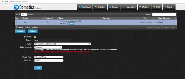
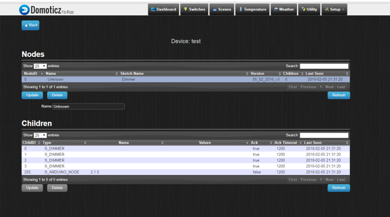
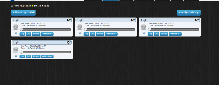
It looks that node is registered with 5 children (I don't know why 5 ).Sketch and some print screens from Domoticz below.
1.

2.

3.

// Testing sketch for 50Hz !
// Dimmer  Arduino
//   |             |
//  GND           GND
//  VCC           5V
//  SYNC        DIGITAL.3
//  CH1         DIGITAL.50
//  CH2         DIGITAL.51
//  CH3         DIGITAL.52
//  CH4         DIGITAL.53
//
//  HC-05       Arduino Mega
//   |             |
//  GND           GND
//  VCC           5V
//  TX            RX (DIGITAL.0)


#define MY_DEBUG  // Enable debug prints to serial monitor
#define MY_GATEWAY_SERIAL // Enable serial gateway
//#define MY_REPEATER_FEATURE
#include <SPI.h>
#include <MySensors.h>
#include <TimerOne.h>    // download this library from arduino.cc
#include <Bounce2.h>
#define BUTTON_1_PIN 4
#define BUTTON_2_PIN 5
#define BUTTON_3_PIN 6
#define BUTTON_4_PIN 7
unsigned char channel_1 = 50; // Output to Opto Triac pin, channel 1
unsigned char channel_2 = 51; // Output to Opto Triac pin, channel 2
unsigned char channel_3 = 52; // Output to Opto Triac pin, channel 3
unsigned char channel_4 = 53; // Output to Opto Triac pin, channel 4
unsigned char Status_button_1;
unsigned char Status_button_2;
unsigned char Status_button_3;
unsigned char Status_button_4;
unsigned char CH1, CH2, CH3, CH4;
unsigned char clock_tick; // variable for Timer1
MyMessage Strefa_1_dimmermsg(0, V_DIMMER);  // Define message name and type to send sensor info
MyMessage Strefa_2_dimmermsg(1, V_DIMMER);
MyMessage Strefa_3_dimmermsg(2, V_DIMMER);
MyMessage Strefa_4_dimmermsg(3, V_DIMMER);
MyMessage Strefa_1_lightmsg(0, V_LIGHT);
MyMessage Strefa_2_lightmsg(1, V_LIGHT);
MyMessage Strefa_3_lightmsg(2, V_LIGHT);
MyMessage Strefa_4_lightmsg(3, V_LIGHT);
Bounce debouncer1 = Bounce();
Bounce debouncer2 = Bounce();
Bounce debouncer3 = Bounce();
Bounce debouncer4 = Bounce();
void setup() {

Serial.begin(9600);
pinMode(channel_1, OUTPUT);// Set AC Load pin as output
pinMode(channel_2, OUTPUT);// Set AC Load pin as output
pinMode(channel_3, OUTPUT);// Set AC Load pin as output
pinMode(channel_4, OUTPUT);// Set AC Load pin as output
pinMode(BUTTON_1_PIN, INPUT_PULLUP); //button channel 1
  pinMode(BUTTON_2_PIN, INPUT_PULLUP); //button channel 2
  pinMode(BUTTON_3_PIN, INPUT_PULLUP); //button channel 3
  pinMode(BUTTON_4_PIN, INPUT_PULLUP);//button channel 4
  // After setting up the button, setup debouncer.
  debouncer1.attach(BUTTON_1_PIN);
  debouncer1.interval(5);
  debouncer2.attach(BUTTON_2_PIN);
  debouncer2.interval(5);
  debouncer3.attach(BUTTON_3_PIN);
  debouncer3.interval(5);
  debouncer4.attach(BUTTON_4_PIN);
attachInterrupt(1, zero_crosss_int, RISING);
Timer1.initialize(75); // set a timer of length 75 microseconds
Timer1.attachInterrupt( timerIsr ); // attach the service routine here

CH1=CH2=CH3=CH4=95; // WHEN ARDUINO START, ALL LIGHT OFF (95 - FULLY OFF ; 5 - FULLY ON) !!!

}
void presentation(){
  sendSketchInfo("Dimmer","05_02_2018_v3");  // Present sketch (name, version)
  for (int sensor=0; sensor<=3;sensor++) // Register all sensors to gw (they will be created as child devices)
  {
    present(sensor, S_DIMMER);}} //Your sensor must first present itself to the controller.
                              //The presentation is a hint to allow controller prepare for the sensor data that eventually will come.
                              // This is done by calling present(child-sensor-id,sensor-type)
                              // Register sensors (id, type, description, ack back)
void timerIsr(){
  clock_tick++;
  if (CH1==clock_tick)
  {
    digitalWrite(channel_1, HIGH); // triac firing
    delayMicroseconds(10); // triac On propogation delay (for 60Hz use 8.33)
    digitalWrite(channel_1, LOW); // triac Off
    }
    if (CH2==clock_tick)
    {
      digitalWrite(channel_2, HIGH); // triac firing
      delayMicroseconds(10); // triac On propogation delay (for 60Hz use 8.33)
      digitalWrite(channel_2, LOW); // triac Off
      }
      if (CH3==clock_tick)
      {
        digitalWrite(channel_3, HIGH); // triac firing
        delayMicroseconds(10); // triac On propogation delay (for 60Hz use 8.33)
        digitalWrite(channel_3, LOW); // triac Off
        }
        if (CH4==clock_tick)
        {
          digitalWrite(channel_4, HIGH); // triac firing
          delayMicroseconds(10); // triac On propogation delay (for 60Hz use 8.33)
          digitalWrite(channel_4, LOW); // triac Off
          }
}
void zero_crosss_int() // function to be fired at the zero crossing to dim the light
{
  // Every zerocrossing interrupt: For 50Hz (1/2 Cycle) => 10ms ; For 60Hz (1/2 Cycle) => 8.33ms
  // 10ms=10000us , 8.33ms=8330us
  clock_tick=0;
  }

void loop() {
Status_button_1=digitalRead(BUTTON_1_PIN);
Status_button_2=digitalRead(BUTTON_2_PIN);

if (Status_button_2==LOW){;
CH1=CH2=CH3=CH4=33;

send(Strefa_1_dimmermsg.set(CH1));
send(Strefa_2_dimmermsg.set(CH2));
send(Strefa_3_dimmermsg.set(CH3));
send(Strefa_4_dimmermsg.set(CH4));
delay(5000);}
if (Status_button_1==LOW){
  CH1=CH2=CH3=CH4=66;

  send(Strefa_1_dimmermsg.set(CH1));
  send(Strefa_2_dimmermsg.set(CH2));
  send(Strefa_3_dimmermsg.set(CH3));
  send(Strefa_4_dimmermsg.set(CH4));
  delay(5000);

}
}
This is what I see in serial port monitor:
(0;0;1;0;3;66
0;1;1;0;3;66
0;2;1;0;3;66
0;3;1;0;3;66
0;0;1;0;3;33
0;1;1;0;3;33
0;2;1;0;3;33
0;3;1;0;3;33) -
Could you plese explain me a little bit more? I'm not sure what are you suggesting.
First I would like to see in domoticz values from Arduino - 33 % or 66% depending on which button I press. -
At the beginning yes, and shortly after I want to control 4 dimmers by Domoticz and by push buttons paralelly.
Second sketch (posted today) it is my testing sketch which I used for learning how communicate with domoticz, but it seems that I have no idea how to doit. -
