This site has the best collection I have found: http://www.embeddedworks.net/wsim3951.html
In the US the T-Mobile pre-paid seems to be the best deal. Similar on sparkfun
https://www.sparkfun.com/products/13186
This site has the best collection I have found: http://www.embeddedworks.net/wsim3951.html
In the US the T-Mobile pre-paid seems to be the best deal. Similar on sparkfun
https://www.sparkfun.com/products/13186
Is anybody connecting to the internet via a SIM card? If so what cellular plan are you using? I think I can stay below 1GB a month and I am in the United States (North Carolina). I know there are a few companies offering M2M Data Only plans but I have not been able to organize what is currently available. I also know Twilio is joining with T-Mobile but I have not seen the plan yet. Does anybody have any information?
The arduino should send a "presentation" message when powered up which could be the "on" message. If there is a way to send a "Powering Down" message at the loss of power by using a capacitor, that would be fantastic. In my setup it would have to have enough juice to send the message via the long range radio. I suspect some of the experts on this forum have done something similar to this solution.
I think the issue with the current sensor is the pump would need to be running for it to work and they are looking to know that the pump could run if it needs to.
This page provides a design based on a capacitive voltage detector (like the "pen" you stick in an outlet to see if it has power): http://electronics.stackexchange.com/questions/94782/capacitive-ac-voltage-detection.
Seems plausible but you could also just power the arduino from the GFCI. I would have the arduino monitor a float switch in the sump pump. You could send a signal indicating the water level every 2 minutes.
If the pump dies or is blocked or malfunctions but the GFCI is still powering the arduino you would get a signal that the water level has risen and is going to flood the basement.
If the GFCI trips and your controller does not receive an update from the sensor you could send an email indicating a possible powe failure. This is a tricky alarm and not all controllers can do it. You need to know when the arduino last sent a message to the controller and act accordingly. You also only want to send one email even if the power is out for a long time. And it is nice to send a follow-up email when the arduino comes back online.
I can do some testting also. Happy to help.
I noticed the web page on connecting the radio does not match the troubleshooting section. Connecting a Decoupling-Capacitor on the Radio page says 4.7µF but the troubleshooting page says 47µF. Seems a bit confusing.
Thanks for sharing this! I am hoping to create an all-in-one extension cord plus this meter. I hope this way I can detect when a pump fails or maybe just how much power is being used.
I have read that you when using a CT you must be careful to avoid a voltage build up on the CT output. Is that a concern with this current setup? With a battery powered arduino you are not grounded? In my extension cord project I was thinking I could use the ground from the extension cord.
I am not an electrical engineer so I may be way off here, just trying to be safe.
I think this setup could be very useful. In the high school greenhouse where I have my sensor network there are so many pumps, heaters, air stones, that need to be monitored and an alert sent if they stop working.
I may also try this with the sensebender micro.
And I just noticed the internet has been down at the greenhouse since early Saturday! More reason to have a local install.
@FotoFieber Just the standard serial gateway. There is a nice node-red node for parsing mysensors serial data. I then have some basic code that recognizes the specific data, e.g. node 9 child 10 is the aquaponics water temperature, so that I can store more information in influxd to mak ethe graphs better.
I also have node-red respond to the metric/imperial question. That is basically it.
@Yveaux The install in the greenhouse is basically because the internet connection is costly and not reliable. I have an old linux computer in teh greenhouse for the following reasons:
@Yveaux Yeah Grafana has been great. I would have something similar to your setup but the greenhouse only has a cell phone hotspot so I wanted to get the data out to the cloud with as little traffic as possible. Then display all the graphs from there (grafana on Amazon)
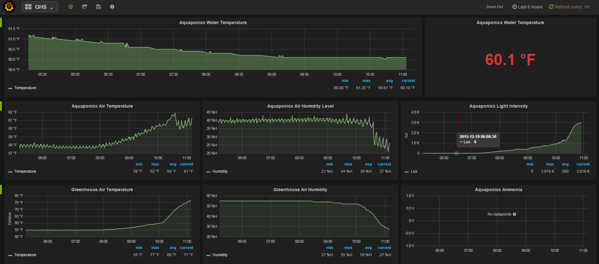
I have been creating a sensor network at a local high school and the mysensors project is basically what makes it possible. I just launched a website on amazon documenting some of what is deployed with live graphs.
http://growing.education/index.php/farm-monitoring-and-automation/garinger-sensor-network/
At this point we are mainly just monitoring and collecting data, so my controller is a very simple node-red installation that saves data locally and transmits data via MQTT to mosquitto runing on an Amazon EC2 instance. Another installation of node-red again saves data to InfluxDB and Grafana displays the data very nicely.
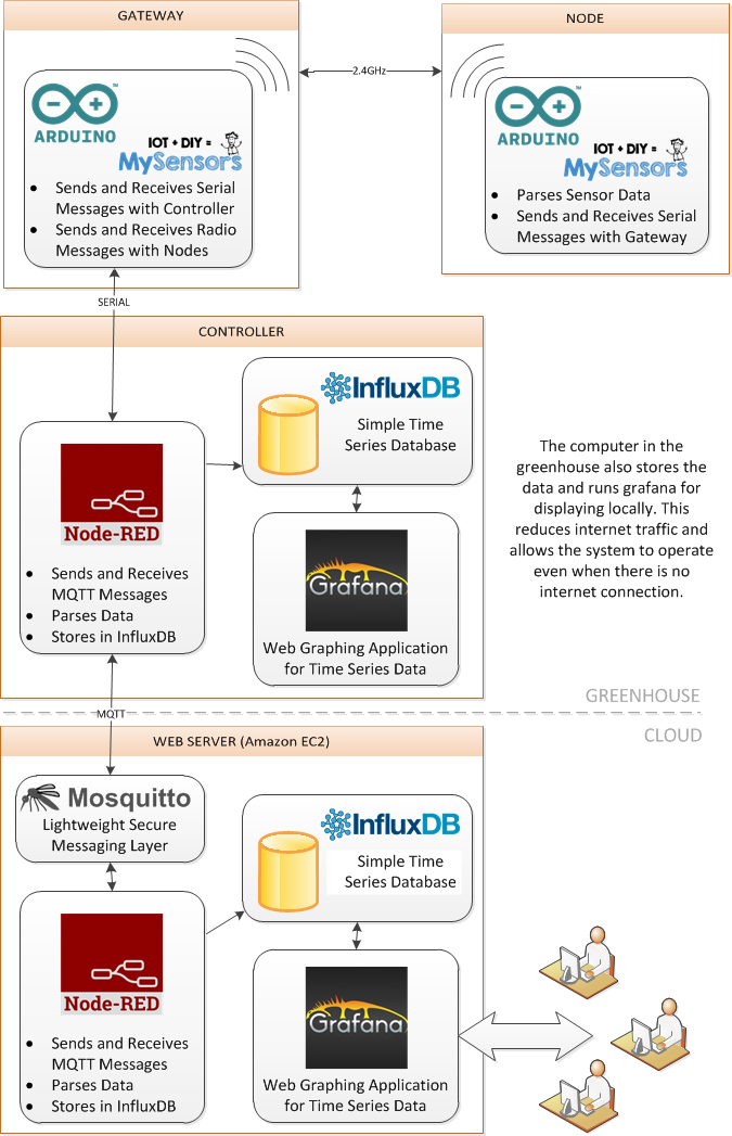
We have three active nodes. One sensebender node running off battery and another solar powered node. A sample of the graphing is below. Check it out. The site is new so I suspect there are many typos and broken links. Thanks again to this community for helping me.
thanks. it is working now.
I have tried bot the long range and normal radios. Everything works fine when connected to an Uno but I only see "radio init fail" on the mega2560.
Some of thes radios are NRF24L01 instead of the NRF24L01+ but I ma able to get them all working on the Uno. I have changed the power setting and data refresh rates but that has no affect.
I saw a post saying the pins should be different on the mega but I ma not sure if that is true and I am having a hard time searching and finding that post.
If anybody has suggestions I would appreciate them.
Awesome - Thanks!
Just an example that I am using (I am sure there are better ways):
  void loop()
{
// Process incoming messages (like config from server)
  gw.process();

 #ifdef CHILD_HUMIDITY
  loopHumid();
 #endif

  #ifdef CHILD_H2O
  loopH2O();
  #endif

  #ifdef CHILD_LUX
  loopLux();
  #endif

  #ifdef CHILD_RELAY
  loopRelay();
  #endif

  gw.wait(SLEEP_TIME); //sleep a bit
}

void loopHumid()
{...
Combining sketches is a big one. I am new to electronics and while I have had good success building 1 or 2 sensor nodes with nanos, minis, and unos I have struggled when attempting to create a multi-sensor node with a LCD panel and radio using a mega2560. I am hoping maybe there are some "best practices" to follow and the wiki could document these.
Ideally I would some programming patterns to follow when writing sketches that make it much easier to combine them. The existing sketches on the MySensors website could be rewritten to follow these patterns.
For example:
How to combine sleep/waits is not completely intuitive in all cases. It seems that maybe these calls should be in the main loop and that the main loop then calls each sensor loop. Are sleep and wait completely interchangeable? Why not always use wait then?
The mysensors library defines the radio pins in the library. That is not very clear and does not match the pattern of all the example build sketches on the site. At first when switching boards I was not sure if the radio needed PWM or not. Changing what pins to use should be an easy thing to do when combining sensors in one sketch so it should be done in a standard way.
Also for sensors like the DS18B20 that can have many sensors attached to the same pin, determining the child ids to avoid conflicts with other sensors on the same node can be tricky. This also raises issues about assigning IDs or requesting IDs. Most sketches let the gateway assign IDs and I am not sure that is easier for a beginner.
Also it seems if you have a problem with the radio ("radio init fail") all other serial output seems to stop (that has been my experience). I am going to start taking the approach of adding the radio first, make sure everything is good. Then add 1 sensor , recheck and so on. To do this quickly I want to be able to quickly add/remove sensors from my sketch. I suspect there is a programming pattern that makes this easy.
My main concern when I started adding multiple sensor types to a single node was conflicts in the imported libraries. I am not confident enough to modify these libraries. Fortunately I have not had any issues, but if people no about conflicts it would be good to document them.
Lastly, maybe we just need an easy place to share sketches. The forum has a Project section but a Sketches library where people could possibly add feedback would be nice.
As always my comments are just suggestions for improvement. The mysensors project is fantastic and i appreciate all the great work.
I have a similar issue. I want to collect data from several locations and potentially also control some relays remotely. Some locations (Haiti0 will need to use a SIM card to send data. So I am looking for a reliable cloud based system to collect data and possibly control.
I stumbled on this http://developers.sensetecnic.com/ , which is free. Lets you store, view data privately, and they host node-red so you can run rules and notifications or send data anywhere. It seems like a great offering but for some reason there is not that many people using it.
The other thing i though about was having the remote locations post the data to dweet.io and then I could retieve from any machine i decide to be the central server. you can also do this privately for a few buck a month. If your channel resembles MQTT then you can run node-red locally and from there do formal MQTT or just a serial connection to any controller or board.
I am still just testing different things. Amazon started their IoT offering yesterday which is currently free.
Thanks. Everything looks very good.
@jkandasa Great. I just tried it. I used send on the activity board and it appears to be doing what i meant by Receive. Of course once you fix that "bug" it may not work like that anymore.
But I did see the data on the chart.