My wife said "I do not want to see "those things""...
Challenge accepted!
(see the gif in action here https://ibb.co/BCbS2Dc )
My wife said "I do not want to see "those things""...
Challenge accepted!
(see the gif in action here https://ibb.co/BCbS2Dc )
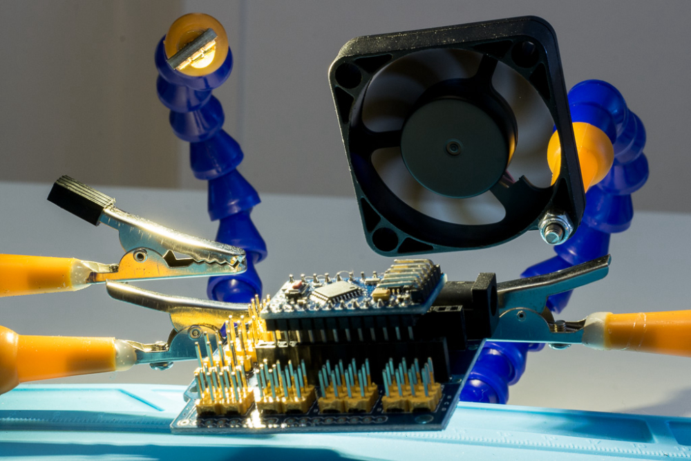
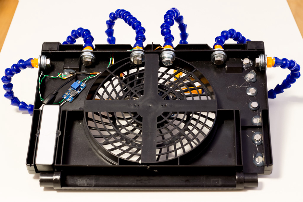
not built today, but someone mentioned fumes extractor, so this is what I built for soldering, light and fume extractor are powered by a small usb rechargeable powerbank. Fan has a active carbon filter behind it and works great for small to medium-ish projects I work on
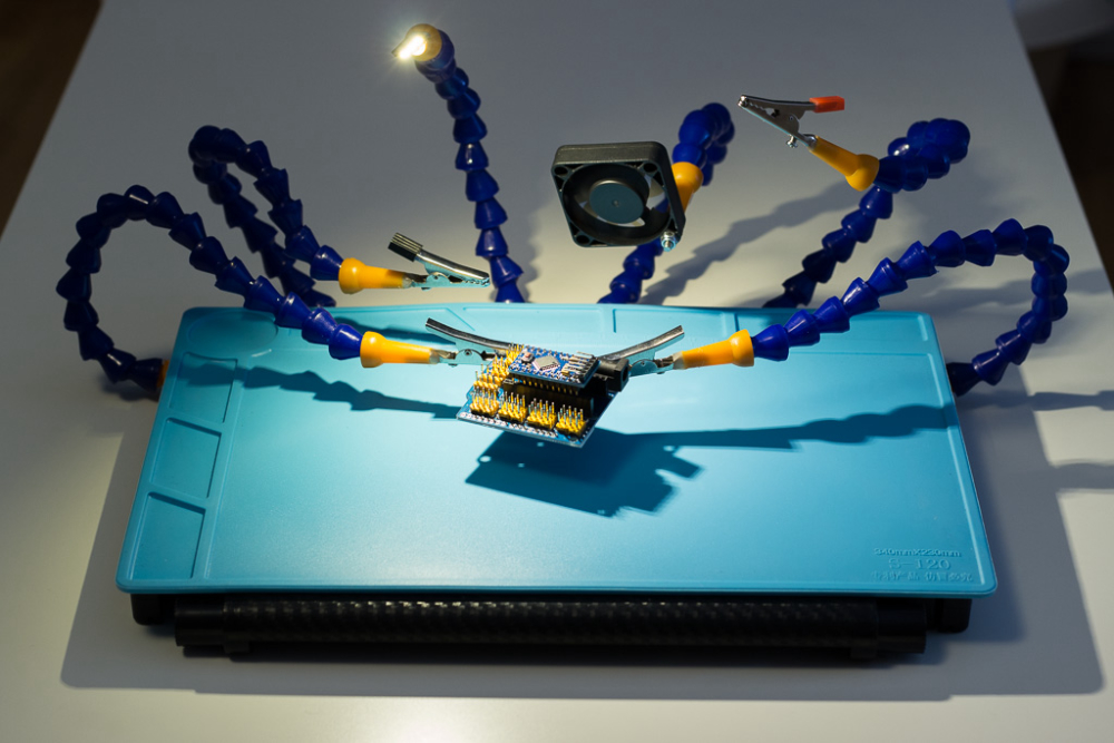
Built case for soldering tools, to easily move them out of the way.
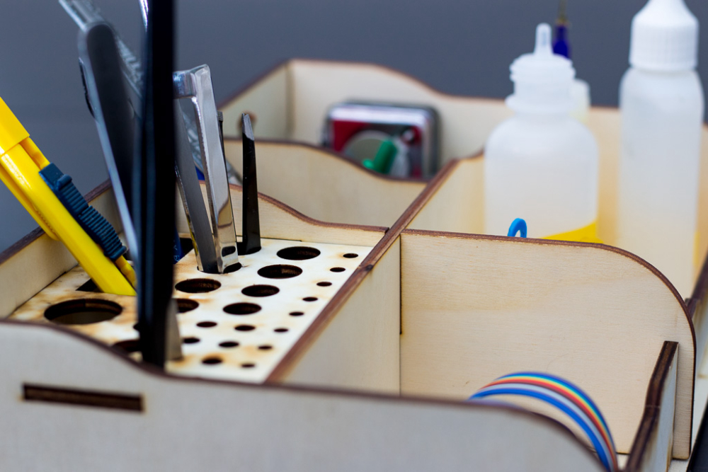
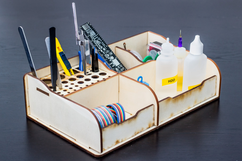
Not really, bought it on banggood and asked wife to assemble it (she likes those type of projects, especially if the office might look a tiny bit cleaner) https://www.banggood.com/DIY-Self-assemble-RC-Model-Tools-Case-Screwdriver-Box-Gripper-Package-Plier-Stand-Retro-Style-p-1257252.html?cur_warehouse=CN
Laser cut plywood(or something), looks quite nice I think. I will order few more when they appear in stock.
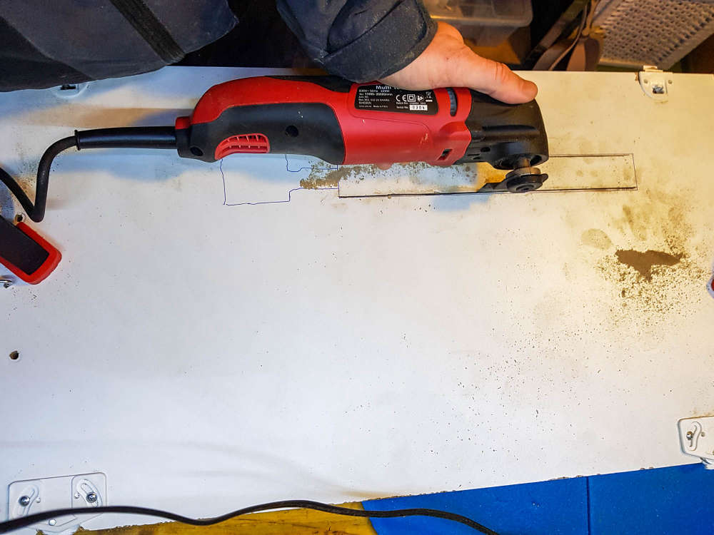
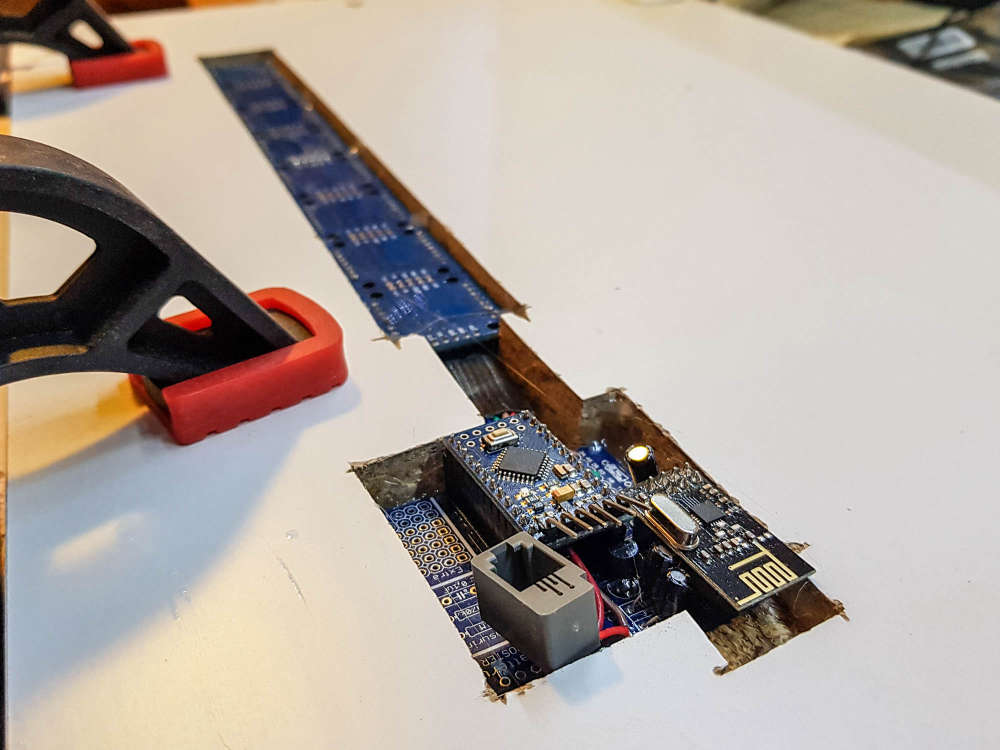
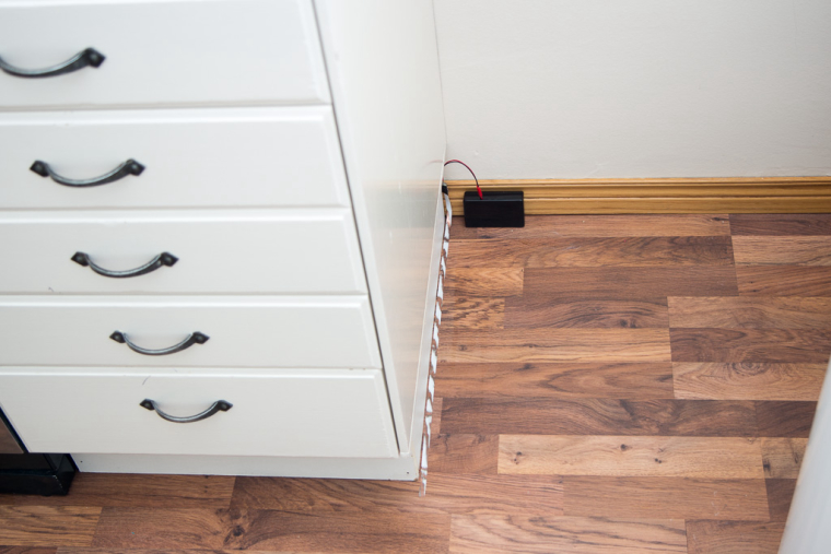
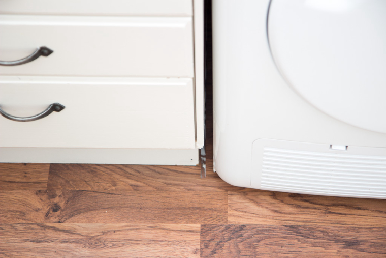
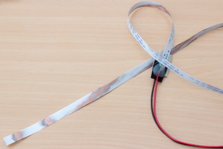
Here is a quick'n'dirty sensor I made using 2m long thin ribbon cable from ebay/aliexpress ($2-3) as a leakage sensor to monitor thumble dryer. Sometimes baby would take out the rubber on the doors, or I would not connect the condenser properly after cleaning and it would leak quite a lot of water on the floor.
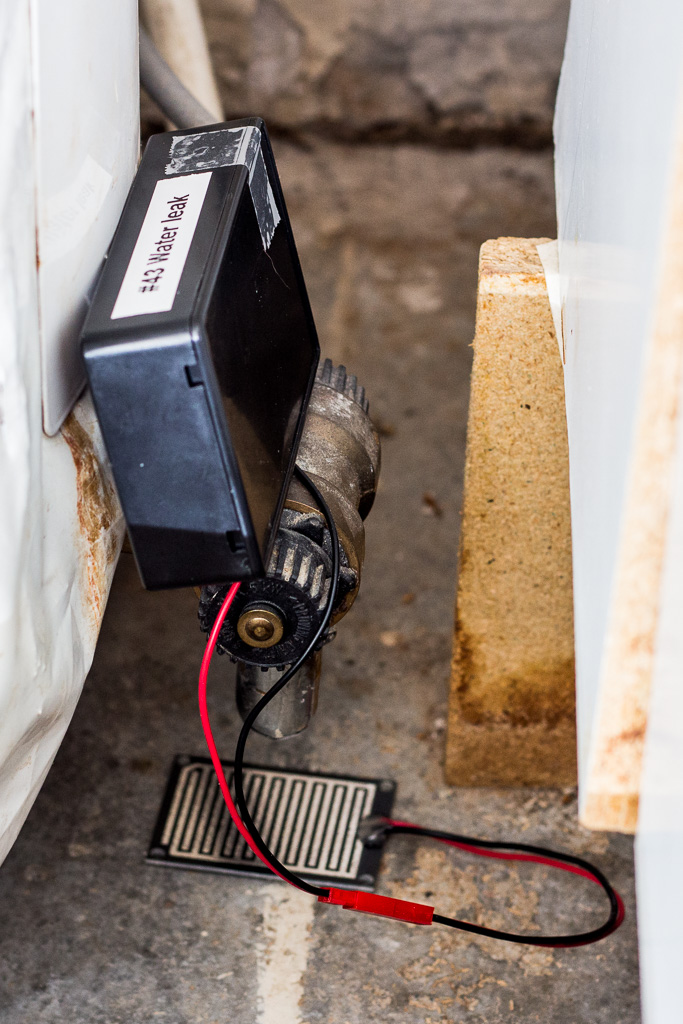
Almost invisible under the appliance
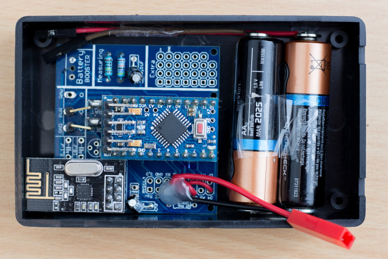
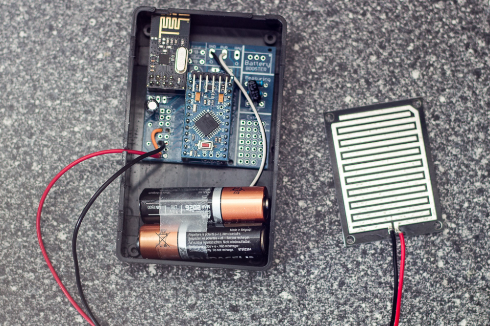
Used the Easy/Newbie pcb as the base, i really get bored of soldering the radio. Also used the little magnets as battery contacts, then the batteries do fit into the small box.
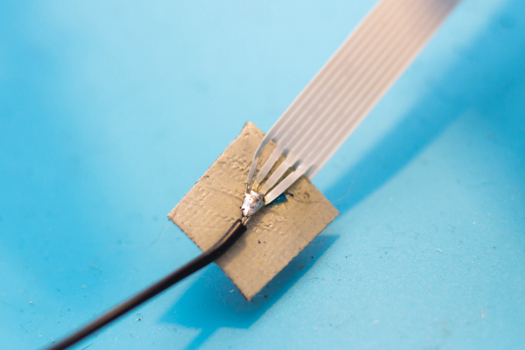
For the sensor/contact itself I "polished" out the insulation on the ribbon using dremel polishing bit every feww centimeters (it is very easy to damage the copper line, so if you plan to reproduce this one, test with few bits). It looks ugly as hell but it is under the dryer so... functionality beats aesthetics here by far.
I connected every second line with one contact, and every second with second contact, which gave me a sensor that would detect smallest drop of water (probably not needed but... playing around).
This is the code I am using, quickly modified the code that @RobKuipers shared (thanks again!) here https://forum.mysensors.org/topic/4827/soil-moisture-sensor/13
I just removed some not needed code and played around with sensitivity. It is checking for value every two minutes and sensitivity value around 50 works fine for me (if case before sending the moisture around line 149).
I also flashed 1mhz bootloader with BOD lowered to 1.8v, so it runs a bit longer on batteries without power stepup module
Here is the code that runs it
/*
 Name:		MYS_MoistureSensor.ino
 Created:	5/25/2017 1:04:35 PM
 Author:	Rob

 Soil moisture measuring by using stainless steel rods (or any other conductor).
 Probably the simplest project ever, since only a MySensors-node and some wire is needed to set things up.

 The sketch alternates current during measuring to prevent corrosion of the rods due to electrolyses.
 Odd readings may occur when starting (eg. increasing soil moisture for no apparent reason), please just allow the electrodes to settle down in the soil.
 No extra hardware needed.

 I use an Arduino Mini 3V3, powered on two AA cells. It is suggested you set the fuses for a lower Brown Out Detection (BOD). But anything goes.

 Just tie D4 and A0 together to one rod, and D5 and A1 to another rod. This is sensor one.
 For the second sensor tie D6 and A2 together to one rod, and D7 and A3 to another rod.
 Connect a pushbutton between GND and D3 if you need a button that makes the node report immediately (can be omitted)

 Measurement are taken every minute and send to the gateway if different from the previous reading.
 In case of no changes, the node reports itself every four hours.
 The output is between 0 (dry) and 100 (wet).

 Can also be used as a depth moisture sensor with three sensor zones; in that case use one (common) long rod and three smaller sensors along
 the height of the rod and configure the sketch accordingly.
	 sensors[0] = { 4, A0, 5, A1, -1, false };
	 sensors[1] = { 4, A0, 6, A2, -1, false };
	 sensors[2] = { 4, A0, 7, A3, -1, false };

*/

#include "Header.h"

// Enable debug Serial.prints to serial monitor
#define MY_DEBUG

#if defined MY_DEBUG
#define Sprintln(a) (Serial.println(a))
#define Sprint(a) (Serial.print(a))
#else
#define Sprintln(a)
#define Sprint(a)
#endif

// Enable and select radio type attached
#define MY_RADIO_NRF24

// Use PA_LOW for RF24+PA (Power Amplifier)
//#define MY_RF24_PA_LEVEL RF24_PA_LOW
//#define MY_RF24_PA_LEVEL RF24_PA_MAX

#define MY_NODE_ID 42

#include <MySensors.h>

#define ACK 0        // = false
#define CHILD_ID 1
#define REPORTNOWSWITCH_PIN 3    // Arduino Digital I/O pin for button/reed switch (must be an interrupt pin!)

#define NUM_MOISTURE_SENSORS 1
#define CHILD_ID_TEMPERATURE (CHILD_ID+NUM_MOISTURE_SENSORS+1)

#define SENSOR1_ROD1_DIGITAL 4
#define SENSOR1_ROD1_ANALOG A0
#define SENSOR1_ROD2_DIGITAL 5
#define SENSOR1_ROD2_ANALOG A1


#define SLEEP_IN_MS 120000		// every minute a new measurement
#define EVERY_15_MINUTES (3600000/4/SLEEP_IN_MS)
#define EVERY_4_HOURS (3600000*4/SLEEP_IN_MS)
#define NUM_READS (int)5		// Number of sensor reads for filtering

int countLoops;
int8_t interruptedBy = -1;
int oldBatLevel;
float oldTemperature;

int output_value;

/// Included in Header.h:
//typedef struct {
//	int digital_input_a;
//	int analog_input_a;
//	int digital_input_b;
//	int analog_input_b;
//	int level;
//	bool connected;
//} sensorWiring;

sensorWiring sensors[NUM_MOISTURE_SENSORS];

MyMessage msgMoistureSensor(CHILD_ID, V_TRIPPED);
//MyMessage msgChipTemp(CHILD_ID_TEMPERATURE, V_TEMP);


void before()
{
	// All buttons as input-pullup as per ATMEGA recommendation to use less power (and more safety)
	// (http://electronics.stackexchange.com/questions/43460/how-should-unused-i-o-pins-be-configured-on-atmega328p-for-lowest-power-consumpt)
	for (int i = 1; i <= 8; i++)
	{
		pinMode(i, INPUT_PULLUP);
	}

	// Now explicity set pins as needed

	// Setup report-now switch, activate internal pull-up
	//pinMode(REPORTNOWSWITCH_PIN, INPUT_PULLUP);

	// Initialize sensor variables

	// Connect Digital pin 4 to Analog input A0 and a metal rod
	// Connect Digital pin 5 to Analog input A1 and another metal rod.
	sensors[0] = { SENSOR1_ROD1_DIGITAL, SENSOR1_ROD1_ANALOG, SENSOR1_ROD2_DIGITAL, SENSOR1_ROD2_ANALOG, -1, false };


	for  (int i = 0; i<NUM_MOISTURE_SENSORS; i++)
		sensors[i].connected = testSensorConnections(sensors[i]);
}

void setup()
{

}


void presentation() {
	sendSketchInfo("Water Leak Sensor no42", "1.1", ACK);

	for (int i = 0; i < NUM_MOISTURE_SENSORS; i++)
	{
		if (sensors[i].connected) present(CHILD_ID+i, S_WATER_LEAK , ACK);
	}
	//present(CHILD_ID_TEMPERATURE, S_TEMP);
}

void loop()
{


	for (int i = 0; i < NUM_MOISTURE_SENSORS; i++)
	{
		if (sensors[i].connected)
		{
			output_value = measure(sensors[i]);

			Sprint(F("output_value is "));
			Sprintln(output_value);
			if ((sensors[i].level != output_value) && output_value > 50)
			{
				sensors[i].level = output_value;
				send(msgMoistureSensor.setSensor(CHILD_ID+i).set(1), ACK);
			}
		}
	}

	// Every fifteen minutes; poll temperature
	if (countLoops%EVERY_15_MINUTES==0)
	{

		int batLevel = getBatteryLevel();
		if ((oldBatLevel != batLevel)) // ...but only when changed, or when button is pressed;
		{
			sendBatteryLevel(batLevel, ACK);
			oldBatLevel = batLevel;
		}
	}

	// So you know I'm alive
	if (countLoops == EVERY_4_HOURS)
	{
		sendHeartbeat(ACK);
		countLoops = 0;
	}

	countLoops++;

	interruptedBy = sleep(SLEEP_IN_MS);
}

// Connect Digital pin 'digital_input_a' to Analog input 'analog_input_a' and a metal rod,
// do the same for b
long measure(sensorWiring sensor)
{
	long total = 0;
	int reading_a = 0;
	int reading_b = 0;

	for (int i = 0; i<NUM_READS; i++) {
		// Left to right
		reading_a = measureOneDirection(sensor.digital_input_a, sensor.digital_input_b, sensor.analog_input_a);
		// Right to left
		reading_b = measureOneDirection(sensor.digital_input_b, sensor.digital_input_a, sensor.analog_input_b);

		total += reading_a + reading_b;
	}
	return map(total / (2 * NUM_READS), 1023, 0, 0, 100);
}

long measureOneDirection(int digital_input_1, int digital_input_2, int analog_input_1)
{
	pinMode(digital_input_2, OUTPUT);
	digitalWrite(digital_input_2, LOW);
	pinMode(digital_input_1, INPUT_PULLUP);
	delayMicroseconds(100);
	long reading = analogRead(analog_input_1);
	//delayMicroseconds(25);
	pinMode(digital_input_1, INPUT);     // High impedance
	pinMode(digital_input_2, INPUT);     // High impedance
	delay(1);

	Sprint(F("measureOneDirection - Reading "));
	Sprintln(reading);

	return reading;
}

// test the connections of both rods of a sensor
boolean testSensorConnections(sensorWiring moistureSensor)
{
	return (testSensorConnection(moistureSensor.digital_input_a, moistureSensor.analog_input_a) && testSensorConnection(moistureSensor.digital_input_b, moistureSensor.analog_input_b));
}

//  test if digital pin is connected to correct analog pin
boolean testSensorConnection(int digital_input, int analog_input)
{
	pinMode(digital_input, OUTPUT);
	digitalWrite(digital_input, HIGH);
	delayMicroseconds(100);
	long reading_1 = analogRead(analog_input);
	digitalWrite(digital_input, LOW);
	delayMicroseconds(100);
	long reading_2 = analogRead(analog_input);
	pinMode(digital_input, INPUT);     // High impedance
	delay(1);

	Sprint(F("testSensorConnection - Reading1 "));
	Sprintln(reading_1);
	Sprint(F("testSensorConnection - Reading2 "));
	Sprintln(reading_2);

	bool correct = ((reading_1 == 1023) && (reading_2 == 0));
	return correct;
}


long readMUX(uint8_t aControl)
{
	long result;

	ADMUX = aControl;
	delay(20); // Wait for Vref to settle
	noInterrupts();
	// start the conversion
	ADCSRA |= _BV(ADSC) | _BV(ADIE);
	set_sleep_mode(SLEEP_MODE_ADC);    // sleep during sample
	interrupts();
	sleep_mode();
	// reading should be done, but better make sure
	// maybe the timer interrupt fired
	while (bit_is_set(ADCSRA, ADSC));
	// Reading register "ADCW" takes care of how to read ADCL and ADCH.
	result = ADCW;

	return result;

}


// Battery measure
int getBatteryLevel()
{
	int results = (readVcc() - 2000) / 10;

	if (results > 100)
		results = 100;
	if (results < 0)
		results = 0;
	return results;
} // end of getBandgap

// when ADC completed, take an interrupt
EMPTY_INTERRUPT(ADC_vect);

long readVcc() {
	long result;
	// Read 1.1V reference against AVcc
	result = readMUX(_BV(REFS0) | _BV(MUX3) | _BV(MUX2) | _BV(MUX1));

	result = 1126400L / result; // Back-calculate AVcc in mV (1024 steps times 1100 mV (1.1V) = 1126400L)

	return result;
}


// Utter nonsense, but needed for attaching an interrupt to...
void debounce() {
}
Now the only question is: How long will copper wire detect the water before corroding? I understand that the code has polarity change to avoid electrolytic effect, but still moisture from the air will certainly corrode exposed wires. If it holds a year that would be ok, everything above that would be great :)
If it doesn't work long enough, then I will just buy some more robust sensor and replace the ribbon strip with it.
My friend had a leakage from the water heater, luckily he was around (and renting) so not much damage was made, so inspired by the incident I made another water leakage sensor for water heater (reusing the code from my previous "ribbon cable sensor" )
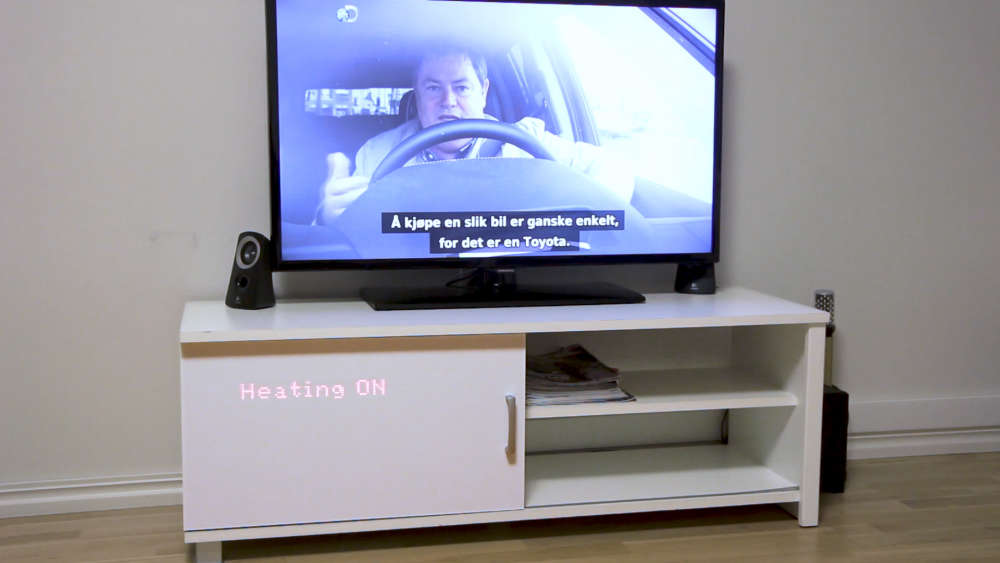
Then I have an "alarm" flow in node-red (via openhab) which blinks all lights in the house, sends notification to mobile phones with high priority etc. Which brings me a lot of joy when all works fine (and annoys my wife, as usual)...
They are so easy to made that I might as well make a few of them just for convenience and "feeling rich with sensors" if you guys know what I mean :)
@sundberg84 just to update success of the story, I cut the vcc trace and connected mini directly to battery, burned the fuses based on your advice here https://forum.mysensors.org/topic/7296/burning-fuses/8, and now the sensor goes down to 2.0v :)
Booster is still used but only for dht22, radio and pro mini run directly from the battery.
Thank you very much guys for help, now I have a foundation (and the knowledge) for more awesome sensors! :)
Exactly the same as @stefaanv and many others, I started with Domoticz and used it for few years, but after a while it was a bit too much "this script for this", and "this hack for that", and this in python and seven virtual switches for that hack... So I was looking into a more robust solution, and I was sold on presentations that leading people of OpenHAB held online, showing the architecture, the reasons and plans, having clear roadmap and long term plan for the system. I feel I understand how and why openhab works the way it does, why it is organized in such a fashion. And that is very important with any software, to have a good documentation (technical, not just for the users).
With domoticz, almost no idea about how it was internally organized, why and what the future plans are. It was always somehow "well this is what we have, it works, and here are the workarounds... with bunch of hidden difficult to find virtual switches and rest api"
When I started making more "abstracted" rules about events and logic, then lua showed quite a few challenges, but it was mainly having 30-40-50 virtual switches, a pain in the ** keeping track them all, making rules for each of them (f.eks. switches for datetime: isSunrise, isMorning, isAfternoon, isEvening, isNighttime, isDaytime..... isSomeoneHome, isMeHome, isWifeHome,... ) And this was actually the biggest issue I had with domoticz, handling and organizing the automation part and virtual switches. At the end I had like 6-7 times more virtual switches then physical ones.
Then I moved in another apartment and decided to try openhab2. It is just way more robust. It didn't took me a long time to get up and running, and having items defined in a text file is a blessing as you can just do a backup, organize them in multiple files, use git (or backup) for versioning. Writing comments also helps A LOT when you come back to the item after few months/years.
Only thing I was struggling a bit is the RFlink, whose binding is not quite ready yet. But I managed to install and use rflink->mqtt "gateway" and all works as expected.
I am also using node-red for logic as @Fabien which I am still learning, but so far it looks much much better and easier to debug.
Not all challenges from above are domoticz related, some are also "me a rookie" related, so not to downspeak on domoticz, it works great! As long as you are comfortable with all above and dont plan to overgrow it. My goal is to make "smarter home", more then just basic rules and remote home. (about remote home, my.domoticz.com for remote access never actually worked for me, noone could/tried to solve it, so I felt it didn't work)
And that is where the community comes in place, it feels that the people on the openhab are more technical, and generally have great technical discussions about best solutions and approaches. F.eks. only for persisting values, you can have multiple completely different database systems, using the advantage of each of them. And each is very easy to install, as they all comply to some "technical rules and documentation". Now that is a downside, as you need to know that you need persistence strategy at all, I wish some would come predefined, but...
I am not developing anything, but I feel there are "big boys" who think hard about issues and then develop a long term and best solution for the problem. And I want a stable and long term solution for my home automation, and waf :)
On the other side, openhab is a bit more technical, but I think that someone who can change mysensors sketches and make that work, can make openhab work as well. They are very focused on "non-technical" user these days, and it shows with every update. I guess home-assistant is pushing its way forward.
(a novel about my life and divorce with domoticz will be published someday, snippet above is just the preview, I have too much caffeine cannot sleep help)
Awesome project, I wish I made something like this.
(I actually wanted to make something like this when I was in school)
Very clean and nice presentation and realization, with a lot of attention to details. All is very realistic, I can imagine that it took quite some time making it.
Thanks for sharing the details!
Success! I fallowed your advice @sundberg84 and just changed boards.txt and got it to work! Simple and without custom bootloaders etc.
I will certainly forget how to do this again after few months, so here is how to burn fuses so that pro mini 3.3v would go down to 1.8v:
I just changed the boards.txt file that I found in folder c:\Program Files (x86)\Arduino\hardware\arduino\avr\boards.txt
What I did is duplicate lines defining existing pro mini. So I searched the file for "pro mini", and there I found 4 "groups" of lines defining different pro mini boards/processors. I copied one of the groups defining Pro Mini (3.3V, 8 MHz) w/ ATmega328 and changed the name of the group from 8MHzatmega328 to (f.eks.) 8MHzatmega328bod1v8. Then change extended_fuses to 0x06 for 1.8v BOD limit. Also changed the title of the board type. The complete block looks like
## Arduino Pro or Pro Mini (3.3V, 8 MHz) w/ ATmega328 BOD at 1.7v
## --------------------------------------------------
pro.menu.cpu.8MHzatmega328bod1v8=ATmega328 (3.3V, 8 MHz, 1v7 BOD)

pro.menu.cpu.8MHzatmega328bod1v8.upload.maximum_size=30720
pro.menu.cpu.8MHzatmega328bod1v8.upload.maximum_data_size=2048
pro.menu.cpu.8MHzatmega328bod1v8.upload.speed=57600

pro.menu.cpu.8MHzatmega328bod1v8.bootloader.low_fuses=0xFF
pro.menu.cpu.8MHzatmega328bod1v8.bootloader.high_fuses=0xDA
pro.menu.cpu.8MHzatmega328bod1v8.bootloader.extended_fuses=0x06
pro.menu.cpu.8MHzatmega328bod1v8.bootloader.file=atmega/ATmegaBOOT_168_atmega328_pro_8MHz.hex

pro.menu.cpu.8MHzatmega328bod1v8.build.mcu=atmega328p
pro.menu.cpu.8MHzatmega328bod1v8.build.f_cpu=8000000L
And in my boards.txt file it starts on line 735
This is the old line for extended_fuses that we are updating/replacing
#pro.menu.cpu.8MHzatmega328bod1v8.bootloader.extended_fuses=0xFD
After restarting Arduino IDE you should see new type of the "processor" of the board in IDE Tools menu. Select the new one we just created "ATmega328 (3.3V, 8 MHz, 1v7 BOD)" and burn the bootloader on the pro mini.
I used Arduino as ISP to burn bootloader, and there are tutorials for that on arduino.cc. If you have real ISP, then it is a bit easier, but you need to figure out your method of uploading bootloader. Check PeteB's video mentioned bellow.
After that you can check that the fuzes are changed properly, by using Avrdude in the method explained in PeteB's video here https://www.mysensors.org/about/fota . You can also just try to power the mini with 2.0v and see if it works :)
This is the only time we use this newly created processor, it is not used in uploading sketches. So after bootloader is uploaded, you will be able to program pro mini "as if nothing happened", meaning you just connect FTDI and compile. But (this is very important!) dont forget to select the regular processor when uploading sketches, the "Arduino Pro or Pro Mini (3.3V, 8 MHz) w/ ATmega328", not the new one we just created. If you try using new processor, I think it will stop at compile process, so just change to regular processor.
Now you can connect the pro mini directly to batteri and have it run down to 1.8v (in theory, radio goes down to 1.9 if all is "perfect")
I just tested one sensor and it goes down to 2.0v without complaining, that is much better then 2.7 from before :)
Thanks, i managed to fix it with a hardware "Another debouncer" from this page
http://playground.arduino.cc/Main/RotaryEncoders
Here is the code that supports click, double click as well as hold (not the prettiest code but hey... works for now :) )
/*
 This is a sample sketch to show how to use the OneButtonLibrary
 to detect click events on 2 buttons in parallel.
 The library internals are explained at
 http://www.mathertel.de/Arduino/OneButtonLibrary.aspx

 Setup a test circuit:
 * Connect a pushbutton to pin A1 (ButtonPin) and ground.
 * Connect a pushbutton to pin A2 (ButtonPin) and ground.
 * The Serial interface is used for output the detected button events.

 The Sketch shows how to setup the library and bind 2 buttons to their functions.
 In the loop function the button1.tick and button2.tick functions have to be called as often as you like.
 */

// 01.03.2014 created by Matthias Hertel
// ... and working.

/* Sample output:

Starting TwoButtons...
Button 1 click.
Button 2 click.
Button 1 doubleclick.
Button 2 doubleclick.
Button 1 longPress start
Button 1 longPress...
Button 1 longPress...
Button 1 longPress...
Button 1 longPress stop
Button 2 longPress start
Button 2 longPress...
Button 2 longPress...
Button 2 longPress stop
*/

#include <MySensor.h>
#include <SPI.h>
#include <Vcc.h>                                    // library for internal reference Vcc reading


// Reference values for ADC and Battery measurements
const float VccMin          = 1.0*2.5 ;             // Minimum expected Vcc level, in Volts. Example for 1 rechargeable lithium-ion.
const float VccMax          = 1.0*3.0 ;             // Maximum expected Vcc level, in Volts.
//const float VccMin        = 2.0*0.6 ;             // Minimum expected Vcc level, in Volts. for 2xAA Alkaline.
//const float VccMax        = 2.0*1.5 ;             // Maximum expected Vcc level, in Volts.for 2xAA Alkaline.
const float VccCorrection   = 3.30/3.42 ;           // Measured Vcc by multimeter divided by reported Vcc
Vcc vcc(VccCorrection);                             // instantiate internal voltage measurement lib

int oldBatteryPcnt = 0;


#define SKETCH_NAME "DoubleLightClickSwitch"
#define SKETCH_MAJOR_VER "2"
#define SKETCH_MINOR_VER "0"


#define LIGHT_SWITCH_PIN 2   // Arduino Digital I/O pin for button/reed switch
#define SECOND_LIGHT_SWITCH_PIN 3 // Arduino Digital I/O pin for button/reed switch
int BATTERY_SENSE_PIN = A0;  // select the input pin for the battery sense point

#define PRIMARY_CHILD_ID 3
#define SECONDARY_CHILD_ID 4

#if (LIGHT_SWITCH_PIN < 2 || LIGHT_SWITCH_PIN > 3)
#error LIGHT_BUTTON_PIN must be either 2 or 3 for interrupts to work
#endif
#if (SECOND_LIGHT_SWITCH_PIN < 2 || SECOND_LIGHT_SWITCH_PIN > 3)
#error SECONDARY_BUTTON_PIN must be either 2 or 3 for interrupts to work
#endif
#if (LIGHT_SWITCH_PIN == SECOND_LIGHT_SWITCH_PIN)
#error LIGHT_BUTTON_PIN and BUTTON_PIN2 cannot be the same
#endif
#if (PRIMARY_CHILD_ID == SECONDARY_CHILD_ID)
#error PRIMARY_CHILD_ID and SECONDARY_CHILD_ID cannot be the same
#endif

MySensor sensor_node;

// Change to V_LIGHT if you use S_LIGHT in presentation below
MyMessage msg(PRIMARY_CHILD_ID, V_TRIPPED);
MyMessage msg2(SECONDARY_CHILD_ID, V_TRIPPED);

#include "OneButton.h"

// Setup a new OneButton on pin A1.
OneButton button1(LIGHT_SWITCH_PIN, true);
// Setup a new OneButton on pin A2.
OneButton button2(SECOND_LIGHT_SWITCH_PIN, true);

unsigned long previousMillis = 0;        // will store last time LED was updated
unsigned long currentMillis = 0;        // will store last time LED was updated
// constants won't change :
const long interval = 10000;           // interval at which to sleep (milliseconds)

// setup code here, to run once:
void setup() {

	sensor_node.begin(NULL, 31); // Light switches are nodes 30+

	// Setup the buttons
	pinMode(LIGHT_SWITCH_PIN, INPUT);
	pinMode(SECOND_LIGHT_SWITCH_PIN, INPUT);

	// Activate internal pull-ups
	digitalWrite(LIGHT_SWITCH_PIN, HIGH);
	digitalWrite(SECOND_LIGHT_SWITCH_PIN, HIGH);

	// Send the sketch version information to the gateway and Controller
	sensor_node.sendSketchInfo(SKETCH_NAME, SKETCH_MAJOR_VER"."SKETCH_MINOR_VER);

	// Register binary input sensor to sensor_node (they will be created as child devices)
	// You can use S_DOOR, S_MOTION or S_LIGHT here depending on your usage.
	// If S_LIGHT is used, remember to update variable type you send in. See "msg" above.
	sensor_node.present(PRIMARY_CHILD_ID, S_DOOR);
	sensor_node.present(SECONDARY_CHILD_ID, S_DOOR);

	// link the button 1 functions.
	button1.attachClick(click1);
	button1.attachDoubleClick(doubleclick1);
	button1.attachLongPressStart(longPressStart1);
	button1.attachLongPressStop(longPressStop1);
	button1.attachDuringLongPress(longPress1);

	// link the button 2 functions.
	button2.attachClick(click2);
	button2.attachDoubleClick(doubleclick2);
	button2.attachLongPressStart(longPressStart2);
	button2.attachLongPressStop(longPressStop2);
	button2.attachDuringLongPress(longPress2);

} // setup


// main code here, to run repeatedly:
void loop() {
	currentMillis = millis();

	// keep watching the push buttons:
	button1.tick();
	button2.tick();


	int batteryPcnt = vcc.Read_Perc(VccMin, VccMax, true);

	if (oldBatteryPcnt != batteryPcnt) {
		// Power up radio after sleep
		sensor_node.sendBatteryLevel(vcc.Read_Perc(VccMin, VccMax, true));

		oldBatteryPcnt = batteryPcnt;
	}


	// Sleep until buttons pressed

	if (currentMillis - previousMillis >= interval) {
		Serial.println("we go sleep");
		previousMillis = currentMillis;

		sensor_node.sleep(LIGHT_SWITCH_PIN-2, CHANGE, SECOND_LIGHT_SWITCH_PIN-2, CHANGE, 0);
	}
} // loop

// ----- button 1 callback functions

// This function will be called when the button1 was pressed 1 time (and no 2. button press followed).
void click1() {
	Serial.println("Button 1 click.");
	sensor_node.send(msg.set(HIGH));
	previousMillis = millis(); //this is somehow buggy, so it becomes a feature
} // click1


// This function will be called when the button1 was pressed 2 times in a short timeframe.
void doubleclick1() {
	Serial.println("Button 1 doubleclick.");
	sensor_node.send(msg.set(HIGH));
	previousMillis = millis(); //this is somehow buggy, so it becomes a feature
} // doubleclick1


// This function will be called once, when the button1 is pressed for a long time.
void longPressStart1() {
	Serial.println("Button 1 longPress start");
} // longPressStart1


// This function will be called often, while the button1 is pressed for a long time.
void longPress1() {
	Serial.println("Button 1 longPress...");
} // longPress1


// This function will be called once, when the button1 is released after beeing pressed for a long time.
void longPressStop1() {
	Serial.println("Button 1 longPress stop");
	sensor_node.send(msg.set(HIGH));
	previousMillis = millis(); //this is somehow buggy, so it becomes a feature
} // longPressStop1


// ... and the same for button 2:

void click2() {
	Serial.println("Button 2 click.");
	sensor_node.send(msg2.set(HIGH));
	previousMillis = millis(); //this is somehow buggy, so it becomes a feature

} // click2


void doubleclick2() {
	Serial.println("Button 2 doubleclick.");
	sensor_node.send(msg2.set(HIGH));
	previousMillis = millis(); //this is somehow buggy, so it becomes a feature
} // doubleclick2


void longPressStart2() {
	Serial.println("Button 2 longPress start");
} // longPressStart2


void longPress2() {
	Serial.println("Button 2 longPress...");
} // longPress2

void longPressStop2() {
	Serial.println("Button 2 longPress stop");
	sensor_node.send(msg2.set(HIGH));
	previousMillis = millis(); //this is somehow buggy, so it becomes a feature
} // longPressStop2


// End
e
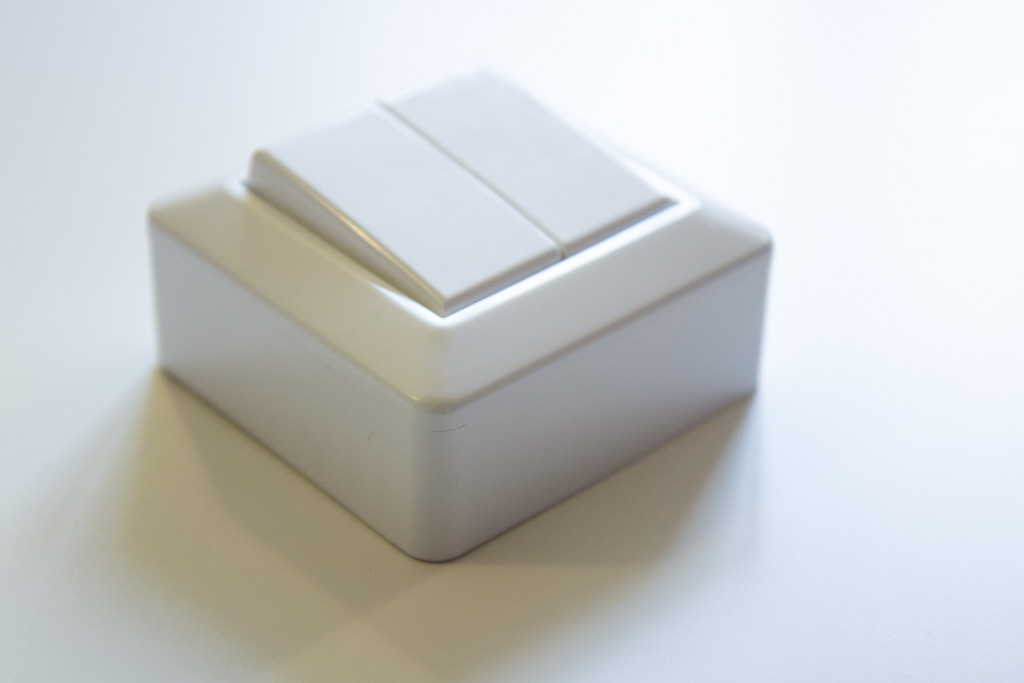
Here are some photos of the switch
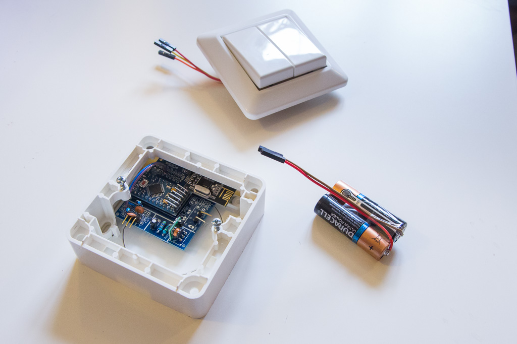
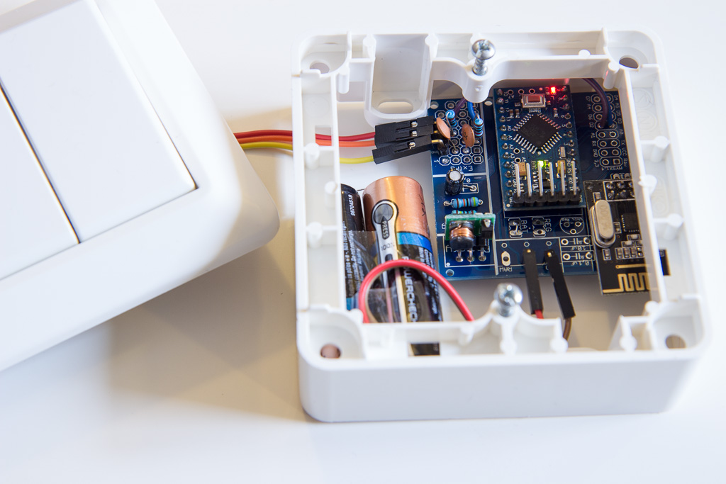
(I know I should not just solder the batteries directly, but... i've done it several times before and none of them complained (duracells take 3-4s with a cheap soldering iron and hold very nice)
Board is the fantastic Easy/Newbie that warms my hart each time I use it
https://www.openhardware.io/view/4/EasyNewbie-PCB-for-MySensors
The switch is not the smallest one (nexa's are waaay more pretier and slimmer) but for what I want to make next, I think MySensors version could work fine.
What would be the best way now to send double click, and eventually "hold" action?
Code can send events on "Button 1 longPress start" and it can send code all the way while you hold the button like bunch of
"
Button 1 longPress...
Button 1 longPress...
Button 1 longPress...
"
and it can send code as "Button 1 longPress stop"
Should I register 4 more CHILD_ID maybe on the switch, and then send CHILD_ID 1 on click, CHILD_ID 2 on double click, CHILD_ID 3 on hold and similar for second button?
At the end I purchased and installed z-wave roller blinds from Swedish company m.nu .
So far so good, and if all is great, I will order three more motors (and two knobs/switches) for living room and terrace doors (which should also automatically keep the shades open if doors er open, to prevent damage).
Made a basic node-red flow that uses xiaomi lux sensor to get them down, but ultimate goal is to have them understand when the light is very bright and when it is "cozy", perhaps even knowing to get the blinds just low enough. Found one good explanation on the internet, will check it out (perhaps use multiple lux sensors strategically placed around the room to determine sun position and strength). Any tips and tricks?
(gif of the action, cannot upload gif to the forum https://media.giphy.com/media/5aY6vSwVn1hsdYC6nd/giphy.gif gif is twice the speed)
Some time passed by but I just wanted to thank you @guillermo-schimmel , I've finally managed to connect sensors properly (at least one of them).
I had to do some changes based on official documentation, so what I did is I just installed mqtt binding from paperUI, and then added one mysensors.things file with fallowing
Bridge mqtt:broker:mosqbroker "Work Broker" [ host="192.168.1.ip", port="1883", secure=false, username="myuser", password="mypassword", clientID="OPENHAB", startupCheckEnabled=false  ]

Thing mqtt:topic:mosqbroker:ChargingStation_Switch4h_raw_thing "Charging station button" (mqtt:broker:mosqbroker) @ "Home" {
    Channels:
        Type string : ChargingStation_Switch4h_raw_button "Charging station 4h button" [ stateTopic="mygateway1-out/31/4/1/0/16"]
}
and then in my items file I had this
String ChargingStation_Switch4h_raw_converted "ChargingStation Switch4h" { channel="mqtt:topic:mosqbroker:ChargingStation_Switch4h_raw_thing:ChargingStation_Switch4h_raw_button"}
and I get the value of the item properly (note I have string for testing, number might be more appropriate here, but that will be fixed another day)
Of course, you and Nca78 did all the thinking anyway :)
I renamed the thread to "How to burn fuses so that pro mini 3.3v would go down to 1.8v [SOLVED]" :) ( or if you have a better suggestion for the topic please write)
Success! @sundberg84 and @Nca78 you will be proud of me when I tell you that I was doing everything "correct" all the time, it is just that arudino IDE had some stupid bug or something. I had to delete everything mentioning Arduino from the pc, and reinstall the IDE, and now all works as expected!
It was a stupid thing hunting me for year(s) now that I think about it. I always assumed that ftdi cannot be used with other then the original bootloader, because of stupid error noone ever heard about :(
At the end, I used this repo https://github.com/joe-speedboat/Arduino-LowPower and added new definitions in the boards.txt, then copied relevant bootloaders (and files in "variants" folder). And repeated all the steps above, and everything works great now. I have a 1mhz arduino blinking correctly, and going down to 1.8v, and sending correct temperatures and all
Life is worth living again!
IT WORKS!! Life is worth living again...
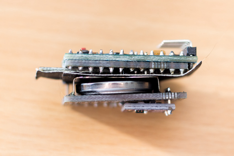
I've assembled now fourth module and it works, only different thing I did is that I have soldered the radio and power jumpers before connecting the module together. It could be that without jumpers essential component of all electronics (white smoke) gets out of the radio, not sure what happened. But it works!
I was struggling a bit to figure out all components needed and all the steps, it might be helpful to have a "short guide", this is for my own reference of what I did in order to get CR2032 module for using with TempHumDoor shield:
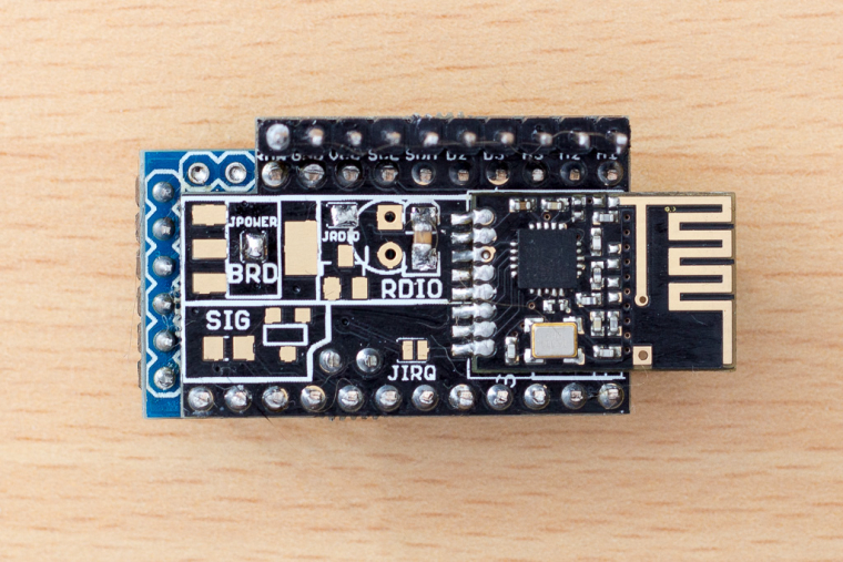
Components needed [nModule]: pro mini, radio, nmodule board, 1 capacitor for radio larger then 4.7uf (I har only 10uf, I have ordered 47uf for future modules).
Assembling process
Upload mockMySensors sketch and check that node works properly (spare yourself a trouble, no point continuing further if this doesn't work) By this point you should have node looking like (better then) this:
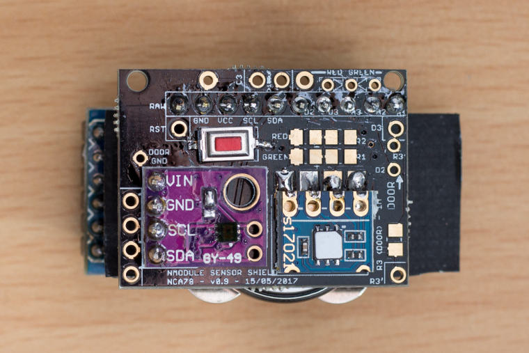
TempHumidityLightDoor shield components: SMD SI7021 for temperature and humidity and a MAX44009 for light, two capacitors larger then 100uf (I used two of 100uf, waiting for 220 to come). And the work so far.
You basically solder these three/four components and the battery holder as described on the shield here https://www.openhardware.io/view/398/NModule-Temperature-Humidity-Light-Door-sensor-shield
I didn't yet solder LEDs, but they are accessible after assembling the module.
Then it looks like this:
Now that nModule #1 is completed, you continue with other modules
Hi,
I started using nModule, https://forum.mysensors.org/topic/6902/nmodule-temperature-humidity-light-door-sensor-shield/
very small node running on (among others) CR2032 button cell battery. @Nca78 has provided some "seed" sketch that is optimized for CR batteries and it works very good, so I was thinking if such optimizations could be implemented in the NodeManager itself for button cell batteries?
Here is the mentioned sketch https://www.openhardware.io/view/398/NModule-Temperature-Humidity-Light-Door-sensor-shield#tabs-source
I am not an expert, but by looking at the sketch, main optimizations are done relatively simple, f.eks. short 400ms sleeping between each data sending, short sleep after presentation, and I guess a few other relevant things (maybe voltage reporting could/should be set differently).
I was considering opening feature request on github, but I was hoping that people who have more experience with button cells would come with more suggestions about what is important so that the nodeManager could be THE plugin for rapid development of battery-powered sensors.
Having this delay between sends (if not already supported) would be a great start. Maybe having a method or a setting in the power management specifically for button cell batteries?
hi again, I noticed that domoticz would lose connection to the Gateway when I would ask one of the nodes to restart. Is that expected behavior?
For example when I want to introduce a new node/code to domoticz, the moment I hit reboot on some node domoticz would report that it has lost TCP connection with the gateway and it would wait 30s or something and then reconnect to the gateway, which is ok to restart but it will then miss the introduction/presentation data sent by the sensor. This is one of the coolest features of MysController, to update and reset remote nodes, without the need to reopen all the nodes and hitting reset or removing the battery etc.
Anyone noticing this, is there some workaround for this?
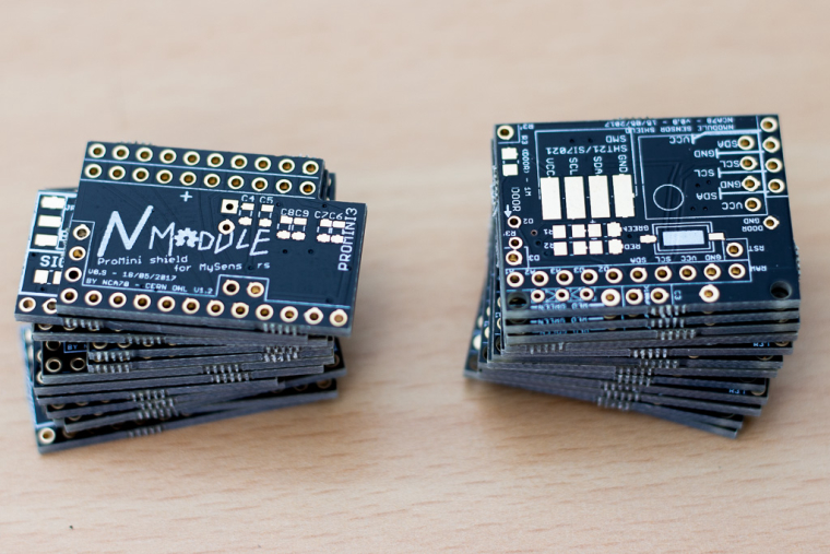
WOW man, this is THE board for mysensors... I've been dreaming about this since I started making nodes :)
And the documentation is equally impressive, one of the best boards and documentations available.
Just wanted to thank you and ask where donations can be made, you deserve at least a beer for this?
P.S. I guess I would be pushing it now after all your hard work documenting the board, but hopefully it would be possible to ordered them directly from the website. But it is not difficult to compile necessary files manually.
Thanks again, keep up the excellent work!
I used d3 for dallas temp sensor but have already soldered d2 to touch sensor. Touch sensor is very unique as it is measuring resistance (actually i think it is measuring time) between to pins, and when you connect 1Mohm resistor between d4 and d2, then radio introduces some other resistance or something, and that messes up the readings for touch. We can use other pins, but pins 2 and 4 are set by default, and it never occurred to me that it is the radio-pin ting.
I have quite a few sleeping sensors where PIR is connected to d2 and door-magnet-sensor is connected to d3 for example, as those are (if I understood it right) pins that can wake up the node from sleeping. Maybe radio can interfere with some of those "common" sensors usually connected to the wake-up pins?
I would then vote for having d2 available in the "available pins" area because it is one of two wakeup pins, and maybe as you suggested have a jumper (or a disconnected line, that can be just shorted with a short wire) that goes to irq.
Anyway, I think it is not an issue-critical as a knife solves it quickly, but it could demoralize us newbies :)
I just wanted to say thanks for this project, I think we need more tools like this that increase quality of our projects (and thus increase WAF as well).
Also wanted to ask would it be too complicated and/or practical to include measurement of the radio consumption while it is sending and sleeping?
Maybe a switch/jumper and a bit of code modification that would let radio sleep, and we could use a amper meter in serial with the radio? Even better if some simple "integrated" current measurement method could be used, some voltage drop on some other pins measured directly in the tester or what not (that would be above my knowledge, but I might just try it in a few months when I get some spare time)