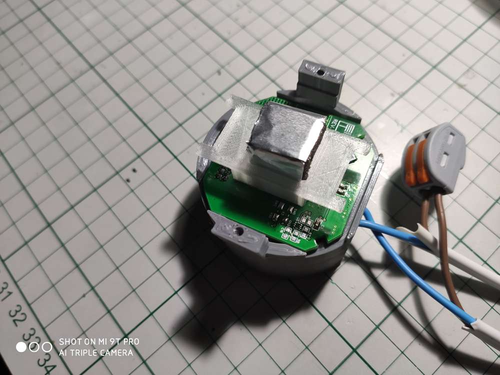
OMG...
Posts made by mtiutiu
-
RE: π¬ No neutral power supply/relay board for in wall switch
Yes, it's available here. The documentation is a little bit scarce I admit but if you understand Apache MyNewt and its build system it should be pretty straightforward theoretically.
I will add more details when I have the time. The code was tested and it's in production. Works without a glitch so far.
-
RE: π¬ No neutral power supply/relay board for in wall switch
@scalz
Thanks.To answer your questions:
- Range is not that "big" if having multiple walls - if more than 1-2 walls things start to degrade but having more nodes in the mesh helps to overcome this. Also one can tune the number of retransmits as shown on my blog and having more relaying nodes will help a lot also. Of course my custom RF design is not perfect or that optimized. Add to that the ceramic antenna which is not that great...
- Power consumption is a plus also indeed as per node I get around 7mA x 3.3V ~ 24mW. Let's add to this the leds and touch capacitive sensor and make it 30mW on average but no more than that. I enabled the internal DC-DC converter of the MCU and add to that the fact that the nodes will stay more in RX mode hence the 6-7mA constant current draw.
- The boards are a little bit different but not much from a RF performance point of view (I'm still learning this part when it comes to PCB layout)
- The hatched ground plane differs around the capacitive pad(s) but that's because the PCB was designed initially using EasyEDA which offers "90 degree" hatches. Then I ported the PCB to KiCAD where I had to do a little trick with some polygons at 45 degree as it doesn't support hatched ground planes (not now at least or in the stable version).
I tested already both designs - the original one and the KiCAD conversion also and both are working as expected.
Yes it was lots of work and especially the power supply PCB design for which the main inspiration was the DER-622 application note from Power Integrations.
But I'm very happy with the overall result. I will update the blog with some real life videos of the whole system in action in the near future also. There will be more blog entries targeting this topic - that's for sure.
-
RE: π¬ No neutral power supply/relay board for in wall switch
For those interested I started "documenting" my work and what I achieved so far on my blog (first time I'm "blogging" ).
-
RE: π¬ NRF52832 1 channel control plate for in wall switch
Same software can be used. The pin definitions need to be changed though.
-
RE: π¬ NRF52832 1 channel control plate for in wall switch
It can be used in a MySensors network if desired. In my case it will be used as part of a Bluetooth mesh network.
-
RE: π¬ No neutral power supply/relay board for in wall switch
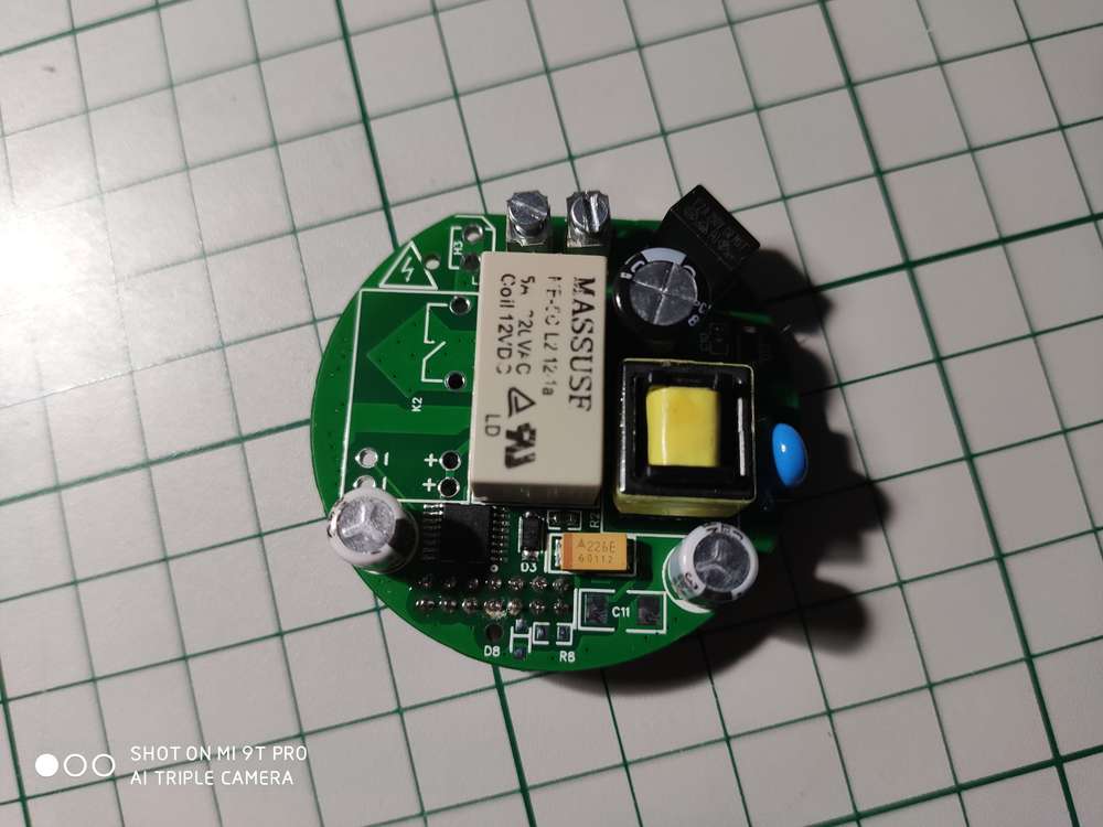
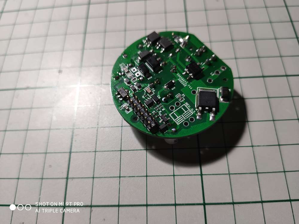
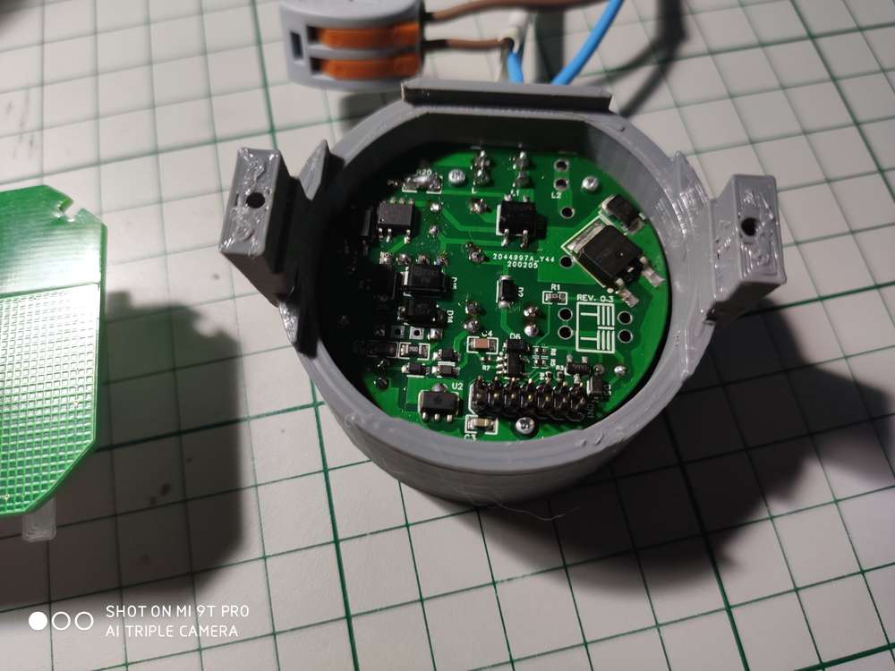
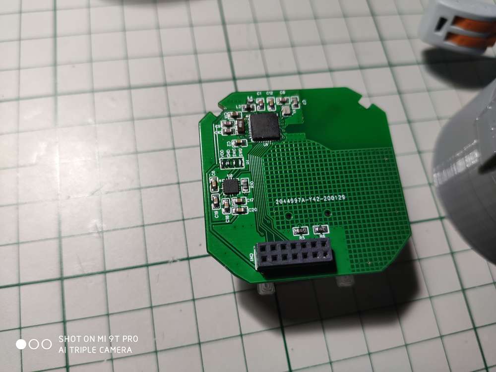
And the real product pictures now:
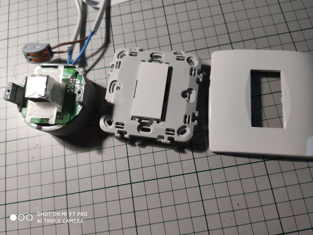
Short demo of touch functionality (will post later on the bluetooth mesh network functionality):
https://streamable.com/b52qb
https://streamable.com/dj3z7Sorry for the solder bridge replacing the R20 inrush current limiting resistor..that's just temporary until I get the real component . And yes, the capacitor across the bulb is still needed but it's a very small one of 0.1uF/250Vac and it should fit near the light bulb on the ceiling (only one is needed if there are two light bulbs on the same circuit).
The aluminum foil wrapped around that sponge is to "extend" the capacitive sensor so that it reaches the front plate fake plastic button. The 3d printed clear plastic around it is to hold it in place and also to spread the small leds light.
Everything is custom made except for the front plastics.
-
RE: π¬ No neutral power supply/relay board for in wall switch
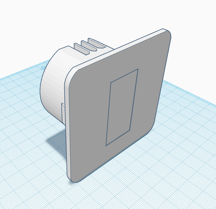
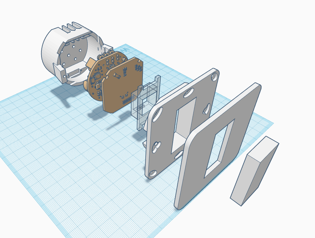
As promised the final design! This is for one channel which I will use mostly in my house. The backside is 3d printed and it holds the electronics. The front panel and fake button are bought from the local store (Leroy Merlin) and I like it very much (it's part of modular switches design and it's very cheap). I could 3d print the front side plastics..but it I can't get the same look and feel - can't beat the molded plastic with a 3d printer for now ... (well you could use some resin or other stuff to fill the holes and then spray paint but still it's a lot of work and it doesn't worth imho)
Here are some pictures from the design. I will post later the pictures with the real product also.
-
RE: π¬ No neutral power supply/relay board for in wall switch
50pcs/lot EE10-A1 Switching Power Supply High Frequency Transformer 220V to 5-12V Maximum Output 3W
https://a.aliexpress.com/_sOShjHIt's the same supplier that I used also and the lot seems to be fine...well at least the 2 pieces that I tested so far .
Now the latching relays. I found them on Aliexpress only and I received something else instead (which seems to happen from time to time) but luckily it works OK so far. So instead of Hongfa relays I got Massuse which seem to be equivalent.
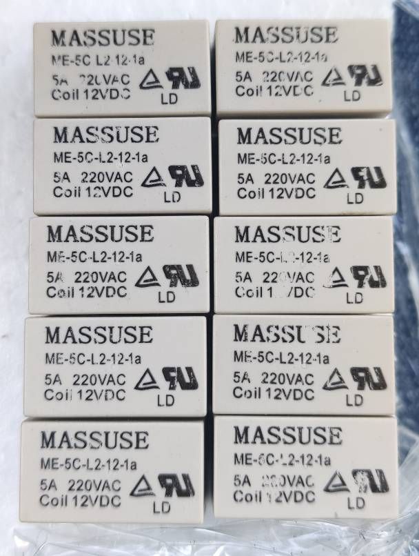
Rest of the components can be sourced from LCSC which is a more trusty component supplier compared to various vendors from Aliexpress (which I already knew..but I didn't had other choices).
Oh and the PCB design and everything else was done using EasyEDA for obvious reasons (JLCPCB is very cheap and pretty good quality for a hobbyist, also their SMT service). I really like their ecosystem - you just create the design using their tool and order everything from there - very, very handy and cheap also as I already mentioned.
-
RE: π¬ No neutral power supply/relay board for in wall switch
I did some final testing and everything seems to work just fine so I can say that this is the final revision. The touch sensing board including radio/mcu must not draw more than 10mA (it will work but won't be stable).
I updated the BOM and schematic with required voltages for caps where it's more important - the rest are 10V or so not that critical (the ceramic caps should be X5R or X7R).
Oh and I replaced the 22uF/25V capacitor with a tantalum type. Initially I used a ceramic one and the board started to sing . Well not quite..it was a more of a buzz because as you all know SMD multi layer caps are known to have this property.
Next step as already mentioned above is to design the enclosure which will be 3D printed with PETG. The front side will be a custom glass plate also which I'm thinking now how to make it look and fit better.
It works slow on my side because...well my free time available for this hobby is kind of limited.
-
RE: Battery powered latching relay node
@iancu
Usually it's best to have an uninterruptible power supply when it comes to building actuators because you want it to "act" all the time. Using batteries for such a thing I wouldn't say it's a reliable choice on the long term.
Imagine what would happen if you do this for a light switch and you come home one day and you find yourself in a situation where you cannot turn on the lights...Of course this very much depends on the final application but still in my opinion actuators should be always powered. -
RE: Battery powered latching relay node
I still don't understand why people are still bothering to use NRF24l01...it's old tech nowadays . Well I get that it's cheaper and bla, bla but when it comes to performance and tuning things up it gets harder imho. Not to forget that you still need another MCU in order to make it work thus increasing BOM and complexity (yes, yes I know why some prefer "decoupled" systems, but still...)
Why not use NRF52832 which is a much more compact solution and let's face it more efficient than the old NRF24L01. Oh and let's not forget that it has a MCU inside also.
I think the list of advantages is obvious:
- More TX power: 4dbm compared to 0dbm.
- Incorporated MCU
- Incorporated DC-DC converter which when enabled will reduce the current consumption in both TX and RX mode (7.5mA in TX mode and 5.4mA in RX mode - this is only for the radio subsystem)
Simplified design when using an already available module like the CDEBYTE or CDSNET from Aliexpress (just search for nrf52832 cdebyte or cdsnet) is also a plus. Those modules are really cheap now - around 3$. Oh and it needs to have those external components (inductors, caps) to be able to use the internal DC-DC converter - the CDEBYTE or CDSNET modules have it.
Now back to this topic main discussion regarding battery powered nodes which need to be pretty responsive no? Well it's not that easy using MySensors to accomplish this - I may be wrong but I tried this for one of my projects and no matter what techniques I used I couldn't achieve the desired results.
Why? Because MySensors it's not designed to create responsive battery powered nodes - please do correct me here @mfalkvidd if I'm wrong. By responsive I mean to make it respond in a time window of <= 1s.@iancu If designing pretty responsive and battery powered nodes then Bluetooth LE is your best bet. I know that it's not MySensors but only BLE can achieve that as far as I know (NRF52832 supports BLE also which is yet another advantage).
I know that this deviates from MySensors and it's not that have something with this project - it's a really great project but we have to know its limitations (as of now at least).
Another alternative would be LORA modules which this project supports also and which have lower RX current because this is the state you would want to stay in most of the time (NRF52832 has it pretty low with the internal DC-DC enabled). But I'm not familiar with LORA modules and from what I've read the TX time cand get very high depending on the modulation speed which is not ideal also.
So what do we need in the end for MySensors: radio modules with very low RX current and fast TX time. Do they exist? I'm not quite sure to be honest (excluding lots of marketing stuff). Faster TX time means also a faster modulation speed/scheme which is achievable even by NRF24l01 so I don't think this is an issue nowadays.
When it comes to MySensors I think a good start is the NRF52832 based modules at least but it won't guarantee the responsiveness that you're looking for @iancu - for that you need a better software stack and radio protocols also imho. -
RE: Modular sketch to be configured with JSON (idea)
Are you suggesting to implement something like esphome has? If that's the case then I would prefer yaml instead of json as it's easier to read and maintain imho.
The idea to have code generated from a configuration file is pretty neat and it simplifies tedious and repeating tasks a lot besides abstraction.
NodeManager should help as it seems to be pretty modular. -
RE: π¬ No neutral power supply/relay board for in wall switch
Started designing the enclosure for 3d printing ... I will use PET-G as it's pretty strong and not very flammable or so it seems after some tests. I don't know about electrical insulation properties yet ...This all very depends on what other compounds are used when it's manufactured.
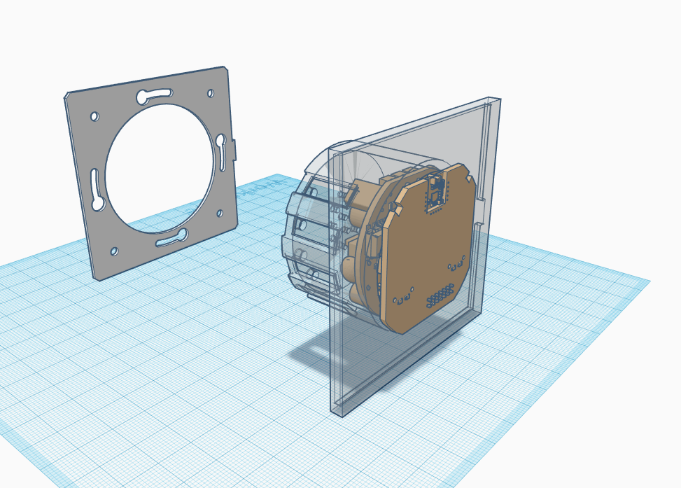
-
RE: π¬ No neutral power supply/relay board for in wall switch
As a general rule it seems that the input capacitor is choosed based on the needed output power which is obvious and the magic formula is (when using a bridge rectifier):
C (uF) = 2 x Pout (W)
So in my case one relay draws about 300mW when switching and we have two so let's take the worst case 600mW. Then the radio part and mcu should not take more than 30mW of power.
Summing up we have 630mW peak which translates to a 1.26uF capacitor and the nearest is 1uF.I just tested with 1uF and it works just fine without a glitch.
So yeah learning new stuff as I go along. I wanted for a long time to learn how to design offline AC/DC converters because the power supply is the most important part of every circuit and so often overlooked.
-
RE: π¬ No neutral power supply/relay board for in wall switch
As a side note: this doesn't mean that the input filtering capacitor is useless in the ac/dc power supplies as it also helps to store energy for the input stage which then gets transferred to the load by the pwm controller. Another useful thing is that it doesn't let the rectified wave voltage to drop too much which may not be very good for the input stage of the pwm controller making it to perform worse.
But in my case and particularly in this application it interferes when the switch "switches" between the two power supplies (well the other one is more of a "series regulator").
I will do some more tests. The most important thing for me right now is the power supply stability and then the thing I was waiting for the most: to create a 2 way setup using 2 switches to drive the same led bulb (for stairways).
-
RE: π¬ No neutral power supply/relay board for in wall switch
Received my boards and started to perform some testing. It worked OK when powering front plates loaded with Bluetooth LE software which are drawing only ~500uA. But as soon as I tried to power a Bluetooth mesh node which draws constantly around 5-6mA then the stand-by supply (the one built around LNK364 IC) didn't acted fast enough when performing the switching causing the BLE mesh node to reset. In other words the power supply startup time was pretty slow for this kind of circuit.
After some serious investigations and headaches (around 3-4 days or so) I finally found why. It has to do with the AC-DC converter "capacitive loading". Initially I though that it was because of the output filtering capacitors and which are also used to store energy between cycling the bi stable relay on and off. As you all know capacitors are good for filtering the ripple and storing electric energy...BUT and very important for this project over here - if they're too big they make the power supply to react a little bit slow.
Why? The reason is very simple: if you use too large capacitors then it takes longer to charge (not to mention about high inrush currents) and because of that they slow down things affecting the AC-DC converter feedback loop.
Well, in a normal use of the power supply and when not cycling between on and off power states too fast this won't be noticed and doesn't matter too much. In my case it matters and guess what? - not the output capacitors were the culprit after tinkering a little bit with their values.
The input filtering capacitor was causing issues. Yes, I'm talking about the input filtering stage after the bridge rectifier. But in this case I started to "attack" the AC/DC power supply in a different way and that is: what happens at the input stage when the supply is switched on and off ?
Let's not forget that in this project the stand-by AC/DC converter is in series with the load (light bulb) and it "breathes" and draws power from the mains voltage and the leakage current from the light bulb which can be very small especially when using LED bulbs.
So what happens actually? As you all know the AC/DC converter won't work if the input AC voltage is less than 85V or so as most are rated to work between 85-265Vac right? But what this means after the rectifier/filtering stage where we have a continuous voltage (let's forget about ripple right now)?
Taking the minimum ac voltage value of 85V this translates to: 85 x 1.41 =~120Vdc. So untill the input filtering capacitor won't reach that dc voltage value the LNK364 chip won't work and here I'm referring to it's internal voltage regulator that powers the internal circuitry or it's "start up" circuit. (in reality it may be less than 120Vdc, but still...)But then you may think: yes, yes but the input filtering capacitor is only 4.7uF - won't it charge fast enough? Well no, and not quite - let's not forget that it's an electrolytic capacitor with higher ESR and not only that - what matters here the most is the fact that the leakage current from the light bulb dictates it's charging rate an that current can be very small !!!
And now you have it - the input capacitor in this case slows down things and affects the power supply start up time. And it doesn't matter that much if you increase the output capacitors and it becomes even worse because then we end up affecting the feedback loop from the converter.
So what I did was to remove completely the input filtering capacitor and now it's damn fast - yes the power supply still works as expected but it's much faster between on and off cycles. And if you look at the original Livolo switch it doesn't have it either but now I understand why.
We have enough filtering at the output stage so it won't affect our powered circuits. It's a little bit noisy at the input but not that much I would say because we have a bridge rectifier. And the load doesn't draw too much current so it should keep up without the input capacitor which also stores energy for the primary inductor. The LNK364 internal MOSFET shouldn't be affected as it's rated to support the peak input values and even more (700Vdc) as the input capacitor was averaging a little bit the rectified voltage waveform (but not that much anyways because it's small value). I will try with a 1uF/2.2uF and see if that slow things again.
So yes..I was almost ready to give up on this project. Now I'm more happy than ever and also because I learned new stuff. And designing/playing with offline AC/DC converters is kinda new for me. There are still many things to learn of course.
I also need to thank @axillent for its "AC-DC at own" post from where I got inspired a little bit.
-
RE: π¬ No neutral power supply/relay board for in wall switch
This board uses the same working principle behind the scenes as the Livolo or Sonoff no neutral switches (some use a triac based implementation). But again the idea is the same - we take advantage of the leakage current from the light bulb. So yes it still requires a capacitor across the bulb in some cases. This is because we power everything via the light bulb which is in series with our circuit and in the end it all comes down to physics law.
So no @arden , this one is not so different compared to the one that you already have. I did this because I'm a more of a diy person and I like to customize stuff and of course learn from it.
Another advantage is that you don't depend on external or 3rd party stuff and you can build/customize it whenever you want (of course this means that you know what you're doing considering the fact that you are dealing with the mains here).
As I live in EU I have only the live wire inside walls for light switches so this is another reason why. I know that there are another ways of accomplishing the same result but I don't want battery powered switches nor putting stuff on or inside my ceiling. -
RE: Cannot flash atmega328 on new custom board
@AdamAnt Regarding the interference between MCU and the radio a pull-up resistor on the CSN line helps. By doing this you can program the MCU without any problems after soldering the radio module.
Now getting back to the main issue here:
- Did you checked for shorts between pins (especially the ICSP part: mosi, miso, sck and also the reset pin to not be shorted to ground keeping the mcu in a reset state). Asking this because I see some pins shifted over there a little bit on the corresponding pads from the PCB.
- Did you checked for continuity between the corresponding MCU pins and the ICSP header?
- Can you post some pictures on how did you wired the USBASP programmer and the ICSP header from the PCB?
The schematic seems fine from my point of view. There may be some problems due to faulty PCBs also from the factory (it happened to me) - that's why I suggested doing the above tests with a multimeter (shorts/continuity test).
-
RE: Watchdog not watchdogging?
It's not portable but for the AVR architecture you can use:
void before() { wdt_disable(); wdt_enable(WDTO_8S); // 8s timeout } void loop() { wdt_reset(); }
Other watchdog options for the AVR architecture here.
-
RE: π¬ RFM69 Livolo 2 channels 1 way EU switch(VL-C700X-1 Ver: B8)
I replied in the nrf51822 thread. Yes I managed to make it work like the original with BLE stack. And using the wonderful Cypress Proc BLE solution including capsense and lots of goodies . Cypress really rocks! I love them.
The current consumption was lowered to 200uA without being connected and 700uA connected. Those numbers include LEDs current consumption and other blocks like touch sensing.
I'll get back with more updates when it's finished.
-
RE: π¬ NRF51822 Livolo 1 channel 1 way EU switch(VL-C700X-1_Ver_C2)
Yep. I managed to make it work as the original one by using only the BLE stack and no external capacitor. The current consumption was lowered to 200uA without being connected and 700uA connected. Those numbers include LEDs current consumption and other blocks like touch sensing.
I'll get back with more updates when it's finished.
-
RE: π¬ RFM69 Serial GW (ATMEGA328P)
The majority of the components are 0603 SMD package type (except 2 smd resistors on the usb lines which are not really mandatory and can be replaced with a solder bridge).
There you go (extracted from schematic - I can't do better than this because it involves more work and I don't have time for it, sorry):
a) 9 x 100nF 0603 SMD MLCC capacitors, X5R/X7R (voltage can be 10V and above)
b) 3 x 1uF 0603 SMD MLCC capacitors, X5R/X7R (voltage can be 10V and above)
c) 1 x 10uF 0603 SMD MLCC capacitor, X5R/X7R (voltage can be 10V and above)
d) 1 x 22uF 0603 SMD MLCC capacitor, X5R/X7R (voltage can be 10V and above)
e) 1 x 10nF 0603 SMD MLCC capacitor, X5R/X7R (voltage can be 10V and above)
f) 1 x ferrite bead 0603 SMD blm18he152sn1d
g) 3 x 330 ohm 0603 SMD resistor
h) 1 x 1Kohm 0603 SMD resistor
i) 1 x 10Kohm 0603 SMD resistor
j) 1 x 56Kohm 0603 SMD resistor
k) 1 x MCP1703A-3302 3.3V/0.25A voltage regulator
l) 1 x TXB0104 voltage level converter
m) 1 x ATMEGA328P-MU AVR MCU (QFN32 package)
n) 1 x CP2102 USB to serial (QFN28 package)
o) 3 x 0603 SMD LEDs (your pick here)
p) 1 x ATSHA204A (SOT-23 package)
q) 1 x RFM69W module (your pick regarding working frequency)
r) 1 x ZTTCS16.00MX ceramic resonator
s) 1 x USB A type male connector for PCB and 1 SMD reset switch (I have no exact links for this, sorry) -
RE: $3ish RFM69 + microprocessor like nRF24LE1 (nRF24L01 + 8051)?
For 8051 cores there's the SDCC project but I don't know how stable/mature is and/or what are its limitations. And it's a C compiler only as far as I know.
-
RE: Recommendation for PCB fab?
AllPCB it's great with DHL shipping. At least for now. It's true that the boards final price includes shipping too but it's still cheaper via DHL. Even if I have to pay VAT it's ok (19%). For the very short time to my door which is 3-4 days that's just WOW compared with 3-4 weeks via regular shipping.
@gohan I tried smart-prototyping in the past and they are pretty ok I can say but not the best compared to PCBWay for example. For cheap services and pretty decent quality I will still opt for Elecrow for example. And for pretty decent quality and very fast shipping - AllPCB - at least for now and if their prices won't go higher in the future.
Oh and AllPCB finishes the boards in 2 days for that price. Compared to EU factories it's still the cheapest - you can't beat China when it comes to that. Here in EU for the same price that AllPCB does I get ONLY 3 boards...wtf..so yeah you get the idea.
-
RE: nRF5 action!
You can find it in my kicad repo: symbol and footprint
I didn't used it in any design so please double check.
-
RE: π¬ RFM69 Raspberry PI Zero(W) Shield(HAT)
I'm sorry but I think I'll abandon this one because I don't have any time left to deal with it.
-
RE: What did you build today (Pictures) ?
@andrew
Where did you buy that green thing that sits on your work desk (it has some kind of ruler on it and squares). I don't know how it's called but I keep seeing it and I think I want one too. Thanks. -
RE: What did you build today (Pictures) ?
I know that this is not the right place to ask but I'm very curious how do you overcome the fact that in EU there's only the live with in the walls for light switches. I saw that you used a HLK-PM0xx module for testing which needs both live and null. Or maybe your "in-wall" wiring is different... Anyways congratulations for your work so far.
-
RE: π¬ NRF51822 Livolo 1 channel 1 way EU switch(VL-C700X-1_Ver_C2)
For the swd connector - some simple wires soldered temporarily :simple_smile: and removed afterwards. The project doesn't support OTA - but can be added if desired as a DFU upload service - needs some extra work and research. But once the switches are flashed there's no need to reflash them as all the MySensors stuff is on the linux board node which can be reconfigured very easily through that web interface(the services behind it will restart automatically when the configuration file changes and the new settings are applied automatically also). I will prepare the required documentation about the whole system on my blog and there's a lot to write :simple_smile: .
-
RE: π¬ NRF51822 Livolo 1 channel 1 way EU switch(VL-C700X-1_Ver_C2)
Hello,
After a long time of development(both hw and sw) I finally managed to get to a final version and a stable one - production ready also. It's a mix of BLE and Mysensors(the switches are running the nordic ble stack wrapped using the sandeepmistry ble peripheral library) and a linux board running the ble central node and Mysensors integration over MQTT.
Now this seems like a complicate setup and extra components added but it's very stable so far and no more failures with the Livolo switches. The linux board has a web interface for configuring mqtt connections details, mysensors node id's, ble mac addresses and some statistics regarding connected nodes over ble and services status, mqtt connection status.
Maximum ble switches or peripherals that the central node can connect to is 5 or 6 - this is a limitation in the ble stack as far as I know but it's enough to cover one room or maybe two if there aren't too many walls or more than 15-20meters in open space. I tested using an Orico BTA-403 usb ble 4.0 dongle and it works very well even through one wall.
Here are some screenshots from the web panel used to configure the central node(linux board with usb ble dongle)
The code from the linux board(a nanopi duo from friendlyelec) runs custom python code made by me to maintain the ble connections and do the MySensors integration - it also provides failure handling and automatic reconnection for both BLE devices and mqtt broker.
Now the web interface is not very refined but it does its job very well(I'm using the great and almighty bootstrap framework for the UI). I also use flask for the python web server, ajax and other goodies to support all this.
Anyway there's a lot to publish and discuss about this project so I will do that on my blog when I have time: https://electronics-adventures.blogspot.ro/
-
RE: π¬ RFM69 Raspberry PI Zero(W) Shield(HAT)
@NeverDie
Thanks. I will keep that in mind. Well I will test and see... -
RE: π¬ RFM69 Raspberry PI Zero(W) Shield(HAT)
In my country there's only one wire in the wall(the live wire) so that's why the Livolo story... And I don't have the luxury of changing the electrical wiring in my house...dig holes or other changes...
-
RE: π¬ RFM69 Raspberry PI Zero(W) Shield(HAT)
That's because of the issues that I had with the supply from the Livolo switches which is designed for low currents(several milliamps and even less). I had no luck with other solutions because of the high current consumption(more than 20mA) - and yes for the Livolo supply this is high. And because of that the stand-by power supply from Livolo crashed(burned) several times and I had to repair it(thanks to @tonnerre33 for his support on this part).
I know that other users managed to make this work with nrf24l01 radios and MySensors support but for me it didn't worked well and it wasn't stable - and trust me I studied the Livolo supply from outside to inside and I know its limitations and why it was designed the way it was designed.
-
RE: π¬ RFM69 Raspberry PI Zero(W) Shield(HAT)
Something like that. For now I'm doing some research to explore and know better the capabilities for such a setup. I had to learn BLE also (obviously) and now I'm playing with BLE Central(raspberry pi zero w board) to receive notifications from the BLE enabled Livolo switch.
But I'm also thinking to link everything over WiFi and MQTT as the high level "transport" because I will need a BLE central node for each room where a Livolo BLE switch resides. So I will see which fits and works best in the end: MySensors radio "transport" over RFM69W vs WiFi and MQTT...
As far as I know MySensors doesn't support a Linux node only a gateway...Initially I was thinking to use each Linux BLE central node as a MySensors node which has BLE Livolo switches attached as "sensors" but I'm not sure about that yet or if it will make sense ...
-
RE: π¬ NRF51822 Livolo 2 channel 1 way EU switch(VL-C700X-1_Ver_C2)
Hi, unfortunately I don't have time and patience for doing BOM's on all of my projects but in this case it's not very hard as the external component count is greatly reduced by using the NRF51822 RF SOC which is a PTR5518 module from Aliexpress. Other than that there is the Microchip touch sense controller - MTCH105 and the usual smd resistors(0603) and caps. Other than that you're not forced to use and solder the onboard dc-dc converter so you don't have to worry about those components - you just need to solder the 3V_EN jumper to use the Livolo 3V output coming from the main relays/power supply board.
-
RE: π¬ NRF51822 Livolo 1 channel 1 way EU switch(VL-C700X-1_Ver_C2)
Thanks. Well because it was cheaper/smaller than all of the Aliexpress modules found so far and it's shielded also(talking about the PTR5518 module here). So I found it to be perfect for this solution when this project was created(almost 2 months ago). Other than that nrf51 even if it's older or not so powerful than its nrf52 counterpart I found it to be more "mature" when it comes to the software part - just like atmega328p is for the Arduino world. If I remember well it was among the first one supported in sandeepmistry's nrf5 core: https://github.com/sandeepmistry/arduino-nRF5 or any other Arduino core for the nrf5xx modules so I assume its software support should be more richer than nrf52xxx.
-
RE: Recommendation for PCB fab?
Elecrow is a good fab imho and yes they are very generous - I received too my boards today and instead of 5pcs I received 11pcs !!!. And this is not the first time they deliver more than requested. The price - 5$ for boards and 3.5$ shipping(standard mail) - 8.5$ in total. And yes they are the cheapest and pretty good quality pcbs - I'm very pleased about their services so far. They beat all the Chinese fabs including shipping so far(and the quality is pretty good - at least for what I need my pcbs for it's well beyond my expectations).
-
RE: SX1211/1212 based radio modules
I know that LORA modules require more TX time..but these are not specified as being LORA modules. Anyways that doesn't mean that your statement is not true - I didn't read all their specs in detail. I don't think TX current matters that much because usually transmissions are short because packets are short - we don't use Mysensors to send lots of data at once and it wasn't designed that way as far as I know. But yeah, it matters how fast the transmitter can do the modulation and which data rate is used.
-
SX1211/1212 based radio modules
Hello,
Did someone saw or know more about these radios: http://www.semtech.com/wireless-rf/rf-transceivers/sx1212/ ? They seem really low power - I never seen such a low RX current(3mA) in active mode(no sleeping) so far on any radio module in the MySensors history :simple_smile: . The radio modules used in this project take around 16mA in RX mode which is pretty much compared to the MCU current consumption(Atmega in most cases - around few milliamps or so).
When used in battery powered nodes this doesn't matter much I know but when used in circuits which should stay active and power requirements must be at a minimum then it matters: for example for the Livolo switch which uses a series power supply that cannot provide more than 5-10mA. This is just a simple thought.
The Semtech site even provides some libraries(written in C of course) as a starting point and some frequency hopping solution for use in a star network configuration based on these modules.
-
RE: π¬ RFM69 Livolo 2 channels 1 way EU switch(VL-C700X-1_Ver_C2)
Hello all,
I studied a little bit more this part of the circuit and it's a standard self oscillating flyback converter or a ringing choke converter as others call it. Indeed it provides the most compact solution for space constrained designs. But all of this comes at a cost: it's difficult to obtain a stable circuit and it has to be tuned by trial and error - at least this is what the literature says.
I'm not a switching power supplies expert here(even though I want to learn more about SMPS's in general but my time is limited for now) but I've come to a conclusion: it's difficult to tune this or to change the existing circuit to accommodate the mysensors circuits power requirements. I tried various combinations using sleep schemes and to change the flyback converter components as other mentioned in the mysensors forum and indeed I can power up my custom design that is presented in this thread BUT it's NOT STABLE. From time to time the switching transistor(mje13003) burns out and this is because I removed the resistor placed at the input of this power supply - near the bridge rectifier and replaced it with a wire(this is not the same resistor as @Lukaspp replaced from the base of the transistor which is the startup resistor for the flyback converter).
Now the only purpose that I imagine for this resistor is to suppress the transients - but it has a big value(100Kohm) which limits the current to a non-usable value for our purpose. I know that there are other solutions to overcome the transients but they are either bulky or too slow for this(correct me if I'm wrong here).
More than that let's not forget that we have 2 power supplies here and when the lights go on the first supply(flyback) input gets shorted by the relays contact(I have the relays variant btw not the one with triac) so I'm thinking that other transients appear here as the primary inductor doesn't like that as far as I know - so I assume the above mentioned resistor of 100Kohm comes into play here too. Another role for it would be to limit the inrush currents. I played with that value too but it needs to be very low to have something stable and I got a value around 200ohms but that doesn't help as it's too low and after some time the resistor burned up and saved my transistor :simple_smile: .
Now with all the tricks in the world and tuning the flyback converter to give more current this won't help as again let's not forget we have a SERIES circuit here so without external intervention we can't achieve that(only if we break somehow the laws of physics or maybe my thinking is limited :simple_smile: ). In this case the external capacitor placed across the light bulb comes into play to supply enough current to the standby circuit which is our flyback converter over here. I played with that one too and from 0,47uF I got to 4.7uF to have a decent result - but this one gets bulky and more expensive from obvious reasons. And let's not forget that the light bulb itself has some impact overall because this is the actual LOAD that we want to control and there are various light bulbs over there with various requirements. More than that they have their power supply embedded which in most of the cases is a(you guessed maybe): a self oscillating FLYBACK CONVERTER or similar. So this one too has inrush currents, transients which are sensed down the line to our dear Livolo switch and affects my custom board stability again :simple_smile: - isn't life beautiful? :simple_smile:
So far these are the results of my trials and none of them proved to be stable so I kinda gave up on this and will try to use a normal powering scheme somehow(as Sonoff switches with a battery powered touch switch on the wall). Not the best solution of all but this is what you get when the infrastructure wasn't thought for this scenarios from the beginning.
The Livolo guys thought of all of this I assume so that's why they stayed only with a simple circuit - a PIC mcu which maybe sleeps most of the time and a simple radio receiver which draws around 5mA or even less - so yeah that's why this works and it's stable in its original form.
-
RE: Another option for AC/DC power? CUI PBO-3 and PBO-5
With those additional components that are required I don't think it's that compact anymore.
-
RE: nRF5 action!
For measuring small currents I'm using Texas Instruments EnergyTrace piece of technology and it works pretty well. You just need one of their development boards with energytrace special microcontroller embedded which is very cheap. More infos here: http://43oh.com/2015/09/how-to-measure-an-energia-applications-power-usage-with-energytrace/
It can be used to measure other boards power usage also - you just need to take of some jumpers and plug in your external board.
It gives you real time energy measurements and with plotting too(and battery life estimation is displayed real time too). No need to worry about burden voltage and other external factors which affect the measurements.
-
RE: nRF5 action!
Even if you're not using the regulator and the CP2102 usb-serial converter there are some leakage currents which are caused by the output stages of those IC's. For example the output stage of the voltage regulator can draw some even if it's not powered. The CP2102 can draw also through the TXD1/RXD1/SUSPEND1 LEDs and the associated GPIO pins P0.11, P0.09, etc.
So to prove and test that the above it's true you need to:
- Desolder the RT9193-33 or at least its output pin(Vout pin 5)
- Desolder R6, R7, R10
This is what I can conclude by looking at that schematic. Any other opinions?
-
RE: Recommendation for PCB fab?
For me, elecrow is the best. But you can query this online tool which is very good: https://pcbshopper.com
-
RE: nRF5 action!
For the ebyte nrf52832 based modules did you had to wire some external components? Are there some other requirements for it in order to work?
Thanks.
-
RE: nRF5 action!
Doesn't work for me so maybe it would be best to obtain a pdf or something readable for all of us from the manufacturer.
-
RE: nRF5 action!
Can you upload those files somewhere so that I can download them? I can't do that from the links you pasted here in this forum.
I also found this altium -> kicad online converter but I don't know how well it works.
-
RE: nRF5 action!
I think that if we use a serial gw based on nrf24l01 pa lna variant should help cover a regular house. At least this is my intent but until then I need to prepare some test environment. And if using nrf5 repeater nodes also should help with coverage - this doesn't work for battery powered nodes I know. But I think there should be some nrf5 nodes that are powered permanently - like actuators for example.
-
RE: nRF5 action!
I think they use Altium Designer and that those are files generated with it.
-
RE: nRF5 action!
My bad. I corrected the initial post. Hope is all well now.
I'm going to try this one too when I have time wt51822-s4at
This is the cheapest of all that I found so far and yes it's not a nrf52832 but a nrf51822 - for my purpose this one is very good too. It doesn't have all the pins exposed - only 7 of them but again it should fit my general usage. I'm curious about its performance though. I'll see that when I get my hands on it. This is the official datasheet(or so it seems): https://4tronix.co.uk/picobot2/WT51822-S4AT.pdf
-
RE: nRF5 action!
For DC-DC converter you need to add some external inductor(s) and some capacitor to the DCC pin if I remember correctly. This can be observed here:
And more than that it needs to be enabled from the SDK also.
I didn't read the official datasheet and the recommendations from it yet...so I don't know all the implications.
From what I've read so far this needs to be added before anything else(I think a good place is the
before
hook from MySensors):void before() { NRF_POWER->DCDCEN = 1; }
And maybe this will shed some light too: https://devzone.nordicsemi.com/question/69091/a-question-about-nrf52832s-dcdc-and-ldo/
-
RE: nRF5 action!
Ok, so after posting some questions to CDSENET Aliexpress store(in regards to the E73-2G4M04S module):
1. Is the nrf52832 IC DEC1 pin decoupled with a 100nF capacitor as per Nordic datasheet recommendations? 2. Is the nrf52832 IC DEC2 pin decoupled with a 100pF capacitor as per Nordic datasheet recommendations? 3. Are all the power pins of the nrf52832 IC decoupled as per Nordic datasheet recommendations? 4. Are the external components already provided so that the internal DC-DC converter can be used?
I received this part of schematic:
The module that I bought is this one: CDSENET E73-2G4M04S
I hope that it helps demystify some things in regards to this module. Maybe @NeverDie can confirm this by checking his module connections as seen in the above schematic. I'm saying this because Chinese support is well..not so user friendly in my experience and I don't know if the above schematic is indeed what they used on their module or they just provided me an example schematic of how to use the NRF52832 IC in general instead.
-
RE: nRF5 action!
@NeverDie
Didn't replied yet. When I get an answer I'll post it here so no worries. -
RE: nRF5 action!
About 6 hours. I asked them too if the Nordic datasheet recommendations were followed or not and if they can provide an example of how to use the module.
-
RE: nRF5 action!
I requested the schematic for the cdebyte module too...but they replied: it's confidential - LOL.
-
RE: nRF5 action!
Why don't you try to program it with a st-link programmer and arduino ide with sandeepmistry nrf5 core installed? I bought that module(E73-2G4M04S) too and I want to know how this part goes. Thanks.
-
RE: nRF5 action!
I used generic and no soft device as Mysensors doesn't use soft devices. I don't know about master-slave, didn't used such a configuration.
You need to create another variant for other pin definitions as this is the way arduino framework works as far as I know.
Never used NFC so I can't give you hints on that, sorry.
-
RE: nRF5 action!
I used the Arduino IDE with sandeepmistry arduino core installed and I managed to program a nrf51822 module with success. I used a cheap st-link programmer from AliExpress. I don't know about nrf52832 as I don't have one. But I don't see why it wouldn't work. You need 4 wires: Vdd(3.3V), GND, SWD and SWCLK.
From Arduino IDE you need to select st-link as programmer.
It uses openocd under the hood to do the work and it worked both on Windows and Linux. On Linux you might need to set udev rules for allowing regular user to use the st-link. -
RE: Livolo, serial, no RF
For sending data then yes the led from optocoupler is powered by the ftdi. The output stage of the optocoupler which is usually a transistor draws power from Livolo but it doesn't need to be high in order to work. I think even 1mA should be enough so the collector resistor should be tuned for that value.
Rc = (Vcc - Vcesat) / Ic => (3.3 - 0.6)V / 1mA = 2.7Kohm
The above ecuation came in my mind for 3.3V logic... hope I didn't missed something - well excluding the current draw by the PIC mcu uart rx input pin which should be very small compared to 1mA.
I think that on the Livolo board the mcu has a 3V supply actually so the resistor would be around 2.4Kohm - but it's not critical so 2.7Kohm should be ok too. Vcesat varies too as other transistor parameters in general.
-
RE: Livolo, serial, no RF
The Livolo power supply is a sensitive topic and it's special by its nature. Being a live wire only design it requires some special design and it cannot deliver high currents - at least not in standby mode when the light is off.
I've struggled with it along with @tonnerre33 and still working on a solution but not without some hacks unfortunately.
But getting back to this topic issue(s): aren't there some low current optocouplers available? The part that draws more current is the LED from it as far as I know. And for strong coupling/better transfer ratio the LED might require more current.
I found this one for example: ACPL-M61L from Avago. They claim that it works at 1mA and even less.
-
RE: π¬ nRF52 Development Board
@NeverDie
I used flux paste like this one:
http://s.aliexpress.com/f67bIZb2And I didn't used preheating because I don't have such a tool. I did just like that guy explained in that video. That's how I soldered the mega328p qfn32 package on my serial gw from here: https://www.openhardware.io/view/316/MySensors-RFM69W-serial-GWATMEGA328P
It's not hard trust me.. just a little bit of patience and after that by practicing a little bit you'll gain experience and see that's just a piece of cake.
-
RE: π¬ nRF52 Development Board
I did it like this guy here: qfn soldering and it worked like a charm. Just be careful not to put too much solder on the pads. But if you use stencils and solder paste it should be much more easier.
I don't have a oven and I don't use stencils.
-
RE: π¬ nRF52 Development Board
I've done this kind of soldering myself and it works with no problems thanks to the laws of physics which @gohan already explained. You just need a little bit more patience when first aligning the component but it doesn't need to be perfectly aligned - the surface tension of the liquid solder will take care of it - just not use too much solder or solder paste though.
-
RE: Livolo, serial, no RF
If you want to repeat (although I don't recommend) this experiment better use some optocouplers instead. This way live wire and ground on the other side is not connected physically.
-
RE: π¬ MySensors NRF5 Platform
Hi,
This is a such great addition for this project. For long time I wanted something like this: a RF SOC with pretty good and usable software support and low power also(and a Cortex arch - pff..that's too much :simple_smile: ). I just wanted to congratulate you for your work and bringing this in to MySensors project - it's very neat and useful.
I tested it and it works just great so far. I would give you 100 likes on openhardware.io if it would be possible :simple_smile: . Thanks once again for your effort.
-
Ota progress checking
Hi,
Sorry if I double post this question maybe but the thing is that I didn't found a clear answer/way of doing this. So my question: is there a way of checking in the main sketch loop(application loop) if an OTA process is ongoing? If so how? Is there a clean/reliable way of checking this? I'm using both 2.1.1 stable release and 2.2.0-beta latest code. I didn't found this in the documentation or maybe I missed it.
I'm asking this because when OTA is in progress the main application loop is executing too and things get a little bit slow and sometimes firmware update stops in the middle.Thanks.
-
RE: π¬ RFM69 Livolo 2 channels 1 way EU switch(VL-C700X-1_Ver_C2)
I see. Yes that's a good thing. Glad I could be of help.
-
RE: π¬ RFM69 Livolo 2 channels 1 way EU switch(VL-C700X-1_Ver_C2)
Ok. I found the issue with pcbs.io service. They don't accept separate files for plated and non plated holes when it comes to gerber files. My default setting when generating gerbers from KiCAD is set to do that.
So here it's a set of gerbers for the boards(1 channel and 2 channel) with PTH and NPTH gerber files merged into one. If you upload these on pcbs.io you'll see that it renders correctly now. And it should be fabricated correctly too if their rendering page corresponds with the real product.- 1 channel variant:
0_1496990513816_livolo_1_channel_1way_eu_switch_rev0.1.zip - 2 channel variant:
0_1496990268774_livolo_2_channels_1way_eu_switch_rev0.1.zip
@shabba
Oh and the 1 channel board: please don't fabricate it yet because it may not fit from a mechanical point of view - the atmega328p is above the big mosfet from the power/relays board. So I have to see if everything fits there. But anyways don't be so impatient because both projects are marked as Work in progress on openhardware.io. I'm saying this because I don't want you or anyone else to waste money before the boards are tested for real. - 1 channel variant:
-
RE: π¬ RFM69 Livolo 2 channels 1 way EU switch(VL-C700X-1_Ver_C2)
That's very odd and not ok. I think their gerber software doesn't support the format that KiCAD generates. I didn't had any problems with other services I used so far - excepting PCBWay. But SeedStudio, Elecrow and even manufacturers from allpcb.com worked just fine. Yes, I use China mostly because it's waaay cheap than EU and the quality is very-very good for my needs.
And your current problem can't be fixed with smd header connectors as @tonnerre33 suggested because there are traces on both sides for the connector. I assume that those pads aren't connected through the board because there aren't any vias or something to pass through. So I think in the end you need to use a standart THT connector and before that you need to drill the board pads for the connector so that you can solder the connector on both sides. And it can be a little bit difficult.
Anyways you should issue a ticket to the pcbs.io service and tell them about this because it's not right at all...Their online gerber viewer doesn't render the connector holes at all and it even reports that the only drills present on the board are those under the touch pads only..
-
RE: π¬ RFM69 Livolo 2 channels 1 way EU switch(VL-C700X-1_Ver_C2)
How so? That's impossible. I used the elecrow pcb manufacturer and the boards are all fine with all the required holes. Where did you sent them for fabrication? Can you send some pictures?
-
RE: π¬ Livolo 3 buttons US/AU switch adapter
Oh man...I wanted things to come faster at my door like you did and in the end I had to pay 6 times!!! the price of the boards because of the customs, DHL fees and so on. But I learned from that and I'll NEVER EVER AGAIN go that way. That's just crazy.
-
RE: livolo Glass Panel Touch Light Wall Switch + arduino 433Mhz
What do you mean? You don't know how the wiring goes? I can provide a simple wiring diagram not a problem if that's needed.
-
RE: livolo Glass Panel Touch Light Wall Switch + arduino 433Mhz
In order to have isolation why not use an optocoupler from arduino to send logic high or low to the livolo relays board? This way they won't share the same gnd and no more issues of this kind in theory. But this means adding the optocoupler as an extra component..but I don't think this is a big issue and it should be cheap also.
-
RE: π¬ RFM69 Livolo 2 channels 1 way EU switch(VL-C700X-1_Ver_C2)
Did you made those modifications that I mentioned of? Also what board did you made in the end - which revision? what schematic? I know you mentioned some github repo but I can't find it right now.
-
RE: π¬ RFM69 Livolo 2 channels 1 way EU switch(VL-C700X-1_Ver_C2)
Ok so this board is basically the same board and it has the same set of components as the previous one(the old one from the old project that I've made) so it should work with both channels or in whatever combination you want. They only changed some components location - that's all. For now I don't know when I'll have time to test - I think only when my boards will arrive from the manufacturer.
-
RE: π¬ RFM69 Livolo 2 channels 1 way EU switch(VL-C700X-1_Ver_C2)
Fixed the diagram posted earlier and now the required solder bridges are visible(R3 and R13 needs to be replaced by a solder/wire bridge as seen in the picture).
This is valable only for the VL-C700X-1 VER: C2 livolo power/relays board hw revision only!
-
RE: π¬ RFM69 Livolo 2 channels 1 way EU switch(VL-C700X-1_Ver_C2)
Yes it seems that the gnd pin is shifted by one position to the right. I will fix that - thanks for noticing. I will do the test with the other channel too. It's sufficient to have one light bulb and capacitor to trigger the other channel too.
-
RE: π¬ RFM69 Livolo 2 channels 1 way EU switch(VL-C700X-1_Ver_C2)
CFL - 15W. No, I wired both bridges.
Here's a quick block diagram for the whole circuit. I hope that I didn't missed anything or wired wrong there.
Well in reality the internal relay contact is not wired like in my diagram but to some extra circuits in order to provide voltage when the switch is closed - this is just a quick and dirty overview of the system.
The test circuit is working now for more than an hour with no problems. Oh..and the old project that I made for Livolo is in production now for more than a month and it works flawlessly.
I tested both CFL and LED bulbs - 5W was the lowest that I tried and it worked perfectly in both cases. The important part here is the parallel capacitor across the light bulb which gives the extra current that the standby circuit needs from the Livolo board in order to power the whole thing. The most sensitive part is the standby circuit because in that case the light bulb is OFF and it cannot provide enough current in this state - this is obvious because the load which is in series is turned off so only a small amount of current is present in the series circuit.
This works for the original board because the touch sensing part draws very little current(under a 1mA I think) and the radio receiver (in the RC variant) which they use draws 5mA or so. This compared with MySensors RFM69W which draws 60mA peak and on average 20-30mA or so.
-
RE: π¬ RFM69 Livolo 2 channels 1 way EU switch(VL-C700X-1_Ver_C2)
Good news everyone! I managed to set up a test board in order to verify the new Livolo relays/power board and with the required modifications IT WORKS!!! as the previous one did from my old project. This time only 2 modifications are required on the board instead of 3 because the 12-14V supply is already connected now to the 2x7 connector.
I expected this to work as the power/relays board didn't changed - they placed the same set of components but in some different places and I was able to recognize the base layout.
@tonnerre33 Maybe yo wired something wrong..but for me it worked from the start. I will post here images and test results so stay tuned.
There you have it in action(sorry for my phone camera and delays): MySensors Livolo in action
Power/relays board required modifications(red lines represent wires - you could desolder those components too and just put some solder/wire bridges)
Next as seen in the video I wired a cheap dc-dc step down converter bought from Aliexpress to the 12-14V pin from the connector and ground and used its 3.3V output to power up the arduino pro mini board. The RELAY 1 - S and 1- R pins mean: channel 1(or 2 - it doesn't matter as the channels are identical) Set and Reset(because we have bi-stable relays). Those were wired to some digital outputs on arduino pro mini as seen here:
-
RE: π¬ RFM69 Livolo 2 channels 1 way EU switch(VL-C700X-1_Ver_C2)
Here: https://forum.mysensors.org/topic/2775/livolo-glass-panel-touch-light-wall-switch-arduino-433mhz/62. I think that @Tigroenot and @jirm know better than me actually. Sorry @Nca78 to involve you on this part. But @tonnerre33 if you wait until next week I'll inspect the new Livolo power board in a little bit more detail and see if I can come up with something.
-
RE: π¬ RFM69 Livolo 2 channels 1 way EU switch(VL-C700X-1_Ver_C2)
Maybe the mosfet bias hack needs to be done also. The truth is that power electronics is not my thing and this power supply is a little bit beyond my understanding...well not that much but some things are not clear for me either. Those hardware modifications were picked from other thread in this forum. Maybe @Nca78 knows better than me this part?
@tonnerre33 did you wired the capacitor across the light bulb as well?
-
RE: π¬ RFM69 Livolo 2 channels 1 way EU switch(VL-C700X-1_Ver_C2)
@tonnerre33 @Nca78 is right. First you need to have a capacitor in parallel with the light bulb (a 0.47uF/275Vac type X2 is enough). This is needed because the power supply from the original Livolo board doesn't provide enough current in standby mode and this is obviously a good reason because otherwise the light bulb will flicker or maybe light up a little bit and this is not wanted. Remember that we talk here about a series circuit and that we need to take power not in the standard way - usually a power supply is made for being wired with both live and neutral and not live wire only as in the current situation.
If the capacitor across the light bulb still doesn't help then you needβ to follow the other steps I mentioned in the first project that I made for Livolo. One of the steps is to wire a bridge across that resistor marked with 104 - you can spot it easily as seen from those pictures that I made at that time. Then if it still doesn't work you need a second wire for the MOSFET biasing - this may be a little hard to see where it goes exactly as the Livolo manufacturer changed the board layout a little bit - not that much from the original one...but I need to figure out.
-
RE: π¬ RFM69 Livolo 1 channel 1 way EU switch(VL-C700X-1_Ver_C2)
I wired the relay channels inputs in parallel on the 2x7 connector as this variant has one relay/channel only but I don't know to which of the ULN2003 IC outputs the relay is connected to on the power/relays board. So basically two of the current buffers from the ULN2003 IC have the inputs tied in parallel which I don't see to be a problem as this IC is designed to have buffers put in parallel(both inputs and outputs).
Hope that the above makes sense.
-
RE: π¬ RFM69 Livolo 1 channel 1 way EU switch(VL-C700X-1_Ver_C2)
Yes I know what you meant. It's L(live) wire only powered. But in order to work it still needs a capacitor across the light bulb as I mentioned in the other project(https://www.openhardware.io/view/306/Livolo-2-channels-1-way-EU-switchVL-C700X-1-Ver-B8) and some modifications on the power board but this time without the 12V line wiring as it's already provided now in the new version by the Livolo manufacturer.
-
RE: π¬ RFM69 Livolo 1 channel 1 way EU switch(VL-C700X-1_Ver_C2)
Yes you're right. And regarding the second question - the functionality is the same but you have Mysensors features on top.
-
RE: π¬ RFM69 Serial GW (ATMEGA328P)
Yes it's ok. Just make sure that you have 10V rated capacitors(this board runs at 5V so it's best to stay above that). On the radio side you can use 6V capacitors as it's powered at 3.3V but anyway...it's easier to use just 10V types instead of remembering what goes where imho.
-
RE: π¬ RFM69 Livolo 1 channel 1 way EU switch(VL-C700X-1_Ver_C2)
And...here comes the 1 channel variant for the classic Livolo switch front plate. Work in progress for both projects(1 and 2 channels)...
-
RE: π¬ RFM69 Livolo 2 channels 1 way EU switch(VL-C700X-1_Ver_C2)
The bom is not fully updated yet. The main difference is the 2x7 connector with 2mm pitch.
-
RE: π¬ RFM69 Serial GW (ATMEGA328P)
@shabba
Sorry but I don't have one now. When I have time I will generate it. For now I'm busy with the Livolo stuff. -
RE: π¬ RFM69 Livolo 2 channels 1 way EU switch(VL-C700X-1_Ver_C2)
OK...another remake for the classic Livolo 2 channels 1 Way EU switch and THE LAST ONE that I will make(well except for the 1 channel one which I need to work on it after this one) - @shabba I know that you waited for this. This is just the other Livolo hardware project of mine "ported" for the new hw revision that the Chinese manufacturer made. They made the 12V line available on the connector and moved it on the opposite side(the new connector is a 2mm pitch one and SMD - I choose to use the THT variant as it doesn't have any impact from a mechanical point of view and it's easier to solder for all of us the mortals around here).
The good news is that the power board is the same as the old one with some minor modifications(more or less):
- the big MOSFET is in the same place but with a 45 degrees orientation
- the power connector is a 2x7 pins one with the 12V line already supplied on one of the pins - less hacks for the board
- the bistable relays are the same and drived by a ULN2003 IC(current buffer) in a TSSOP package
Thanks to @tonnerre33 for creating the new board outline which I borrowed from his project. The rest of the board is the same as the other one that I made with the dc-dc converter moved on the opposite side and with some rearrangements. Next I need to create the boards AGAIN using some external manufacturer(China of course) and then wait...and patience and... patience again and...wait.
And as always big thanks to the Mysensors community for their great effort and for maintaining this great project.
Oh...and for some reason the boards are not rendered correctly in the browser - I'm referring to the openhardware.io gerber viewer(both 2D and the 3D one) - maybe it has to do with the latest changes from KiCAD regarding the way the gerber are generated or maybe some bug in there? (I'm using the latest nightly version). The Linux gerbview utility displays them correctly.
-
RE: π¬ RFM69 Livolo 2 channels 1 way EU switch(VL-C700X-1 Ver: B8)
It's not finished yet. That's just a draft for the upcoming new hardware. When it's finished I'll publish it. As I said all of my work is done using my free time. For now I'm on vacation...will start working again on this project next week.
-
RE: Drag traces?
Isn't the same behavior achieved by pressing the D key(from Drag) instead of M(from Move) ?
-
RE: My Ethernet Gateway Board (W5500)
Nice work. I was thinking to try out the W5500 chip before stumbling across this topic. Were you able to share the SPI port between W5500 and radio module?
-
RE: π¬ RFM69 Serial GW (ATMEGA328P)
And to use higher baudrates for the serial port on the mcu also. To achieve higher baudrates you need a higher mcu clock frequency too.
-
RE: π¬ RFM69 Serial GW (ATMEGA328P)
@tonnerre33
Because at 3.3V the atmega328p mcu can run at max 8MHz as per datasheet. So I wanted it to run at double the speed and for that it needs 5V as per datasheet again. Why at 16MHz? Well because I want the gateway to be more faster in general and to quickly process the incoming messages from the entire radio network.