Skip to content
  • MySensors
  • OpenHardware.io
  • Categories
  • Recent
  • Tags
  • Popular
Skins
  • Light
  • Brite
  • Cerulean
  • Cosmo
  • Flatly
  • Journal
  • Litera
  • Lumen
  • Lux
  • Materia
  • Minty
  • Morph
  • Pulse
  • Sandstone
  • Simplex
  • Sketchy
  • Spacelab
  • United
  • Yeti
  • Zephyr
  • Dark
  • Cyborg
  • Darkly
  • Quartz
  • Slate
  • Solar
  • Superhero
  • Vapor

  • Default (No Skin)
  • No Skin
Collapse
Brand Logo
mtiutiuM

mtiutiu

@mtiutiu
Hardware Contributor
About
Posts
168
Topics
4
Shares
0
Groups
1
Followers
1
Following
0

Posts

Recent Best Controversial

  • 💬 RFM69 Livolo 2 channels 1 way EU switch(VL-C700X-1 Ver: B8)
    mtiutiuM mtiutiu

    After a really long time I received the boards. I finished the assembly for one and uploaded some code to it. So far it seems to work but I need to perform some more tests. I attached some pictures of the finished product.0_1488214929606_IMG_20170227_163301.jpg .0_1488214943223_IMG_20170227_163325.jpg 0_1488214954367_IMG_20170227_163649.jpg

    The silkscreen text is a little bit blurry and it was a little bit too small for the fab to print it so in some places is not right...anyways this is not important but the functionality is.
    One note: the board round edges may be a little bit off the limits but that can be corrected by using some abrasive paper to remove the excess material(which I did in the above pictures and then the board fitted perfectly).

    OpenHardware.io mysensors livolo

  • Recommendation for PCB fab?
    mtiutiuM mtiutiu

    @Nca78

    Elecrow is a good fab imho and yes they are very generous - I received too my boards today and instead of 5pcs I received 11pcs !!!. And this is not the first time they deliver more than requested. The price - 5$ for boards and 3.5$ shipping(standard mail) - 8.5$ in total. And yes they are the cheapest and pretty good quality pcbs - I'm very pleased about their services so far. They beat all the Chinese fabs including shipping so far(and the quality is pretty good - at least for what I need my pcbs for it's well beyond my expectations).

    General Discussion

  • 💬 NRF51822 Livolo 1 channel 1 way EU switch(VL-C700X-1_Ver_C2)
    mtiutiuM mtiutiu

    @NeverDie

    Thanks. Well because it was cheaper/smaller than all of the Aliexpress modules found so far and it's shielded also(talking about the PTR5518 module here). So I found it to be perfect for this solution when this project was created(almost 2 months ago). Other than that nrf51 even if it's older or not so powerful than its nrf52 counterpart I found it to be more "mature" when it comes to the software part - just like atmega328p is for the Arduino world. If I remember well it was among the first one supported in sandeepmistry's nrf5 core: https://github.com/sandeepmistry/arduino-nRF5 or any other Arduino core for the nrf5xx modules so I assume its software support should be more richer than nrf52xxx.

    OpenHardware.io mysensors livolo nrf51

  • nRF5 action!
    mtiutiuM mtiutiu

    @toyman

    You can find it in my kicad repo: symbol and footprint

    I didn't used it in any design so please double check.

    My Project

  • Recommendation for PCB fab?
    mtiutiuM mtiutiu

    @NeverDie

    For me, elecrow is the best. But you can query this online tool which is very good: https://pcbshopper.com

    General Discussion

  • 💬 RFM69 Livolo 2 channels 1 way EU switch(VL-C700X-1_Ver_C2)
    mtiutiuM mtiutiu

    OK...another remake for the classic Livolo 2 channels 1 Way EU switch and THE LAST ONE that I will make(well except for the 1 channel one which I need to work on it after this one) - @shabba I know that you waited for this. This is just the other Livolo hardware project of mine "ported" for the new hw revision that the Chinese manufacturer made. They made the 12V line available on the connector and moved it on the opposite side(the new connector is a 2mm pitch one and SMD - I choose to use the THT variant as it doesn't have any impact from a mechanical point of view and it's easier to solder for all of us the mortals around here).

    The good news is that the power board is the same as the old one with some minor modifications(more or less):

    1. the big MOSFET is in the same place but with a 45 degrees orientation
    2. the power connector is a 2x7 pins one with the 12V line already supplied on one of the pins - less hacks for the board
    3. the bistable relays are the same and drived by a ULN2003 IC(current buffer) in a TSSOP package

    Thanks to @tonnerre33 for creating the new board outline which I borrowed from his project. The rest of the board is the same as the other one that I made with the dc-dc converter moved on the opposite side and with some rearrangements. Next I need to create the boards AGAIN using some external manufacturer(China of course) and then wait...and patience and... patience again and...wait.

    And as always big thanks to the Mysensors community for their great effort and for maintaining this great project.

    Oh...and for some reason the boards are not rendered correctly in the browser - I'm referring to the openhardware.io gerber viewer(both 2D and the 3D one) - maybe it has to do with the latest changes from KiCAD regarding the way the gerber are generated or maybe some bug in there? (I'm using the latest nightly version). The Linux gerbview utility displays them correctly.

    OpenHardware.io mysensors livolo

  • 💬 MySensors NRF5 Platform
    mtiutiuM mtiutiu

    @d00616

    Hi,

    This is a such great addition for this project. For long time I wanted something like this: a RF SOC with pretty good and usable software support and low power also(and a Cortex arch - pff..that's too much :simple_smile: ). I just wanted to congratulate you for your work and bringing this in to MySensors project - it's very neat and useful.

    I tested it and it works just great so far. I would give you 100 likes on openhardware.io if it would be possible :simple_smile: . Thanks once again for your effort.

    OpenHardware.io contest2017 nrf52 mysensors nrf5 nrf51

  • 💬 NRF51822 Livolo 1 channel 1 way EU switch(VL-C700X-1_Ver_C2)
    mtiutiuM mtiutiu

    @NeverDie

    For the swd connector - some simple wires soldered temporarily :simple_smile: and removed afterwards. The project doesn't support OTA - but can be added if desired as a DFU upload service - needs some extra work and research. But once the switches are flashed there's no need to reflash them as all the MySensors stuff is on the linux board node which can be reconfigured very easily through that web interface(the services behind it will restart automatically when the configuration file changes and the new settings are applied automatically also). I will prepare the required documentation about the whole system on my blog and there's a lot to write :simple_smile: .

    OpenHardware.io mysensors livolo nrf51

  • nRF5 action!
    mtiutiuM mtiutiu

    Ok, so after posting some questions to CDSENET Aliexpress store(in regards to the E73-2G4M04S module):

    1. Is the nrf52832 IC DEC1 pin decoupled with a 100nF capacitor as per Nordic datasheet recommendations?
    2. Is the nrf52832 IC  DEC2 pin decoupled with a 100pF capacitor as per Nordic datasheet recommendations?
    3. Are all the power pins of the nrf52832 IC decoupled as per  Nordic datasheet recommendations?
    4. Are the external components already provided so that the internal DC-DC converter can be used?
    

    I received this part of schematic:

    0_1500878901299_E73-2G4M04S.png

    The module that I bought is this one: CDSENET E73-2G4M04S

    I hope that it helps demystify some things in regards to this module. Maybe @NeverDie can confirm this by checking his module connections as seen in the above schematic. I'm saying this because Chinese support is well..not so user friendly in my experience and I don't know if the above schematic is indeed what they used on their module or they just provided me an example schematic of how to use the NRF52832 IC in general instead.

    My Project

  • 💬 RFM69 Livolo 2 channels 1 way EU switch(VL-C700X-1 Ver: B8)
    mtiutiuM mtiutiu

    @MiKa

    I bought this switch(non-radio variant): https://www.aliexpress.com/item/Free-Shipping-White-Crystal-Glass-Switch-Panel-EU-Standard-VL-C702-11-Livolo-AC-110-250V/512770913.html?spm=2114.01010208.3.11.JqUULi&ws_ab_test=searchweb0_0,searchweb201602_4_10065_10068_10000009_10084_10083_10080_10082_10081_10060_10062_10056_10055_10037_10054_10033_10059_10032_10099_10078_10079_10077_10000012_10103_10073_10102_10000015_10096_10052_10053_10107_10050_10106_10051-10050,searchweb201603_9,afswitch_5,single_sort_0_total_tranpro_desc&btsid=518f103c-2c52-4311-9b72-2375b87824c5

    The power/relays board looks like this:
    1_1483961846054_IMG_20170109_133029.jpg 0_1483961846053_IMG_20170109_132955.jpg

    OpenHardware.io mysensors livolo

  • Modular sketch to be configured with JSON (idea)
    mtiutiuM mtiutiu

    @monte

    Are you suggesting to implement something like esphome has? If that's the case then I would prefer yaml instead of json as it's easier to read and maintain imho.
    The idea to have code generated from a configuration file is pretty neat and it simplifies tedious and repeating tasks a lot besides abstraction.
    NodeManager should help as it seems to be pretty modular.

    Development json nrf52 fota

  • 💬 RFM69 Livolo 2 channels 1 way EU switch(VL-C700X-1 Ver: B8)
    mtiutiuM mtiutiu

    Ok some updates to follow:
    performed first tests on the switch power supply/relays board and the results are very promising so far as you can see here

    1. switch is OFF: the so called 12V line gives us 12.63V
      0_1485786554384_resized-IMG_20170123_224320.jpg

    2.switch is ON: the so called 12V line gives us 14.3V
    0_1485786640467_resized-IMG_20170123_224333.jpg

    1. switch power supply/relays board ONLY(without the front plate): 12.8V
      0_1485786734419_resized-IMG_20170123_224730.jpg

    2. a closer look at the switch power supply/relays board and wiring for the unregulated 12V input
      0_1485786806389_resized-IMG_20170123_225001.jpg

    3. switch power supply/relays board with attached dc-dc step down converter for ~3.3V output
      0_1485786881877_resized-IMG_20170123_233052.jpg

    The above scenarios were tested with and without the front plate and I achieved the same and constant results on the dc-dc step down converter output: a steady 3.25V(as I managed to get by adjusting the on board trimmer). The DC-DC step down regulator is a cheap one bought from aliexpress which does the job pretty well.

    Next I will add the arduino board that I prepared for testing(with code). Basically I created a setup based on:

    1. Arduino pro mini @ 8MHz/3.3V
    2. TTP223 touch sensor based modules
    3. RFM69W radio on an nrf24l01 adapter pcb board
    4. Breadboard and wires of course :simple_smile:

    After attaching the above setup to the real livolo switch I will come back with the next set of results. Stay tuned.

    OpenHardware.io mysensors livolo

  • 💬 RFM69 Livolo 2 channels 1 way EU switch(VL-C700X-1 Ver: B8)
    mtiutiuM mtiutiu

    @jirm

    You're a genius!!! I forgot about the parallel capacitor which has to be put on the load(light bulb). I picked a 470nF and a 20W fluorescent light bulb and it works like a charm now and with RFM69W too!!!. Thanks so much for reminding me about the capacitors. Now I can continue and finish this project. Will come back later when my PCB's arrive and assemble the final product. Stay tuned.
    Big congrats to @jirm, @DJONvl and @Tigroenot and the rest of the community of course which contributed with the knowledge to make this possible. This is really a big step ahead.

    OpenHardware.io mysensors livolo

  • 💬 RFM69 Livolo 2 channels 1 way EU switch(VL-C700X-1 Ver: B8)
    mtiutiuM mtiutiu

    Hi all,

    So after some time of testing I give you the final revision of this board which is 0.5. The latest files are available on the openhardware.io page but always the most recent are on my github repo of course(I'll try to keep both in sync anyways). By using good tantalum caps where required I got a good stability for the node. It will be kept for testing for one month still starting from this week(testing already started). So far I'm very satisfied with the results.

    As a final note for all of you there: when designing hardware always use good components - especially good filtering capacitors because most of the issues and instability happens because of that.

    I will try to design the pcb for the one channel variant of the switch too when I'll get my hands on it so stay tuned. I see that some people asked why RFM69 instead of NRF24L01: this is because the RFM69 module is superior in terms of performance/stability/range compared to the latter(trust me it worth the money difference as I tested both along time). And because it works in the sub-GHz band it's also less prone to interference compared to the 2.4GHz band which is used by all Wi-Fi equipment.

    OpenHardware.io mysensors livolo

  • 💬 nRF52 Development Board
    mtiutiuM mtiutiu

    @NeverDie

    I did it like this guy here: qfn soldering and it worked like a charm. Just be careful not to put too much solder on the pads. But if you use stencils and solder paste it should be much more easier.

    I don't have a oven and I don't use stencils.

    OpenHardware.io nrf52 arduino

  • 💬 No neutral power supply/relay board for in wall switch
    mtiutiuM mtiutiu

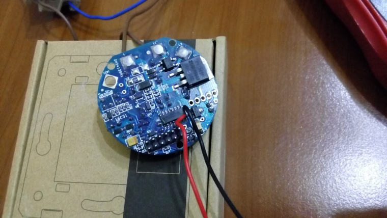
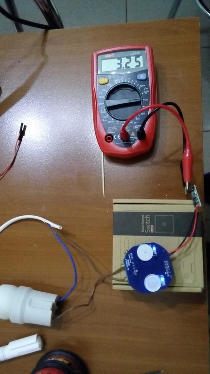
    Received my boards and started to perform some testing. It worked OK when powering front plates loaded with Bluetooth LE software which are drawing only ~500uA. But as soon as I tried to power a Bluetooth mesh node which draws constantly around 5-6mA then the stand-by supply (the one built around LNK364 IC) didn't acted fast enough when performing the switching causing the BLE mesh node to reset. In other words the power supply startup time was pretty slow for this kind of circuit.

    After some serious investigations and headaches (around 3-4 days or so) I finally found why. It has to do with the AC-DC converter "capacitive loading". Initially I though that it was because of the output filtering capacitors and which are also used to store energy between cycling the bi stable relay on and off. As you all know capacitors are good for filtering the ripple and storing electric energy...BUT and very important for this project over here - if they're too big they make the power supply to react a little bit slow.

    Why? The reason is very simple: if you use too large capacitors then it takes longer to charge (not to mention about high inrush currents) and because of that they slow down things affecting the AC-DC converter feedback loop.

    Well, in a normal use of the power supply and when not cycling between on and off power states too fast this won't be noticed and doesn't matter too much. In my case it matters and guess what? - not the output capacitors were the culprit after tinkering a little bit with their values.

    The input filtering capacitor was causing issues. Yes, I'm talking about the input filtering stage after the bridge rectifier. But in this case I started to "attack" the AC/DC power supply in a different way and that is: what happens at the input stage when the supply is switched on and off ?

    Let's not forget that in this project the stand-by AC/DC converter is in series with the load (light bulb) and it "breathes" and draws power from the mains voltage and the leakage current from the light bulb which can be very small especially when using LED bulbs.

    So what happens actually? As you all know the AC/DC converter won't work if the input AC voltage is less than 85V or so as most are rated to work between 85-265Vac right? But what this means after the rectifier/filtering stage where we have a continuous voltage (let's forget about ripple right now)?
    Taking the minimum ac voltage value of 85V this translates to: 85 x 1.41 =~120Vdc. So untill the input filtering capacitor won't reach that dc voltage value the LNK364 chip won't work and here I'm referring to it's internal voltage regulator that powers the internal circuitry or it's "start up" circuit. (in reality it may be less than 120Vdc, but still...)

    But then you may think: yes, yes but the input filtering capacitor is only 4.7uF - won't it charge fast enough? Well no, and not quite - let's not forget that it's an electrolytic capacitor with higher ESR and not only that - what matters here the most is the fact that the leakage current from the light bulb dictates it's charging rate an that current can be very small !!!

    And now you have it - the input capacitor in this case slows down things and affects the power supply start up time. And it doesn't matter that much if you increase the output capacitors and it becomes even worse because then we end up affecting the feedback loop from the converter.

    So what I did was to remove completely the input filtering capacitor and now it's damn fast - yes the power supply still works as expected but it's much faster between on and off cycles. And if you look at the original Livolo switch it doesn't have it either but now I understand why.

    We have enough filtering at the output stage so it won't affect our powered circuits. It's a little bit noisy at the input but not that much I would say because we have a bridge rectifier. And the load doesn't draw too much current so it should keep up without the input capacitor which also stores energy for the primary inductor. The LNK364 internal MOSFET shouldn't be affected as it's rated to support the peak input values and even more (700Vdc) as the input capacitor was averaging a little bit the rectified voltage waveform (but not that much anyways because it's small value). I will try with a 1uF/2.2uF and see if that slow things again.

    So yes..I was almost ready to give up on this project. Now I'm more happy than ever and also because I learned new stuff. And designing/playing with offline AC/DC converters is kinda new for me. There are still many things to learn of course.

    I also need to thank @axillent for its "AC-DC at own" post from where I got inspired a little bit.

    OpenHardware.io switch power supply

  • 💬 No neutral power supply/relay board for in wall switch
    mtiutiuM mtiutiu

    As promised the final design! This is for one channel which I will use mostly in my house. The backside is 3d printed and it holds the electronics. The front panel and fake button are bought from the local store (Leroy Merlin) and I like it very much (it's part of modular switches design and it's very cheap). I could 3d print the front side plastics..but it I can't get the same look and feel - can't beat the molded plastic with a 3d printer for now ... (well you could use some resin or other stuff to fill the holes and then spray paint but still it's a lot of work and it doesn't worth imho)

    Here are some pictures from the design. I will post later the pictures with the real product also.

    exploded_view.png
    one_piece.png

    OpenHardware.io switch power supply

  • 💬 No neutral power supply/relay board for in wall switch
    mtiutiuM mtiutiu

    @scalz
    Thanks.

    To answer your questions:

    • Range is not that "big" if having multiple walls - if more than 1-2 walls things start to degrade but having more nodes in the mesh helps to overcome this. Also one can tune the number of retransmits as shown on my blog and having more relaying nodes will help a lot also. Of course my custom RF design is not perfect or that optimized. Add to that the ceramic antenna which is not that great...
    • Power consumption is a plus also indeed as per node I get around 7mA x 3.3V ~ 24mW. Let's add to this the leds and touch capacitive sensor and make it 30mW on average but no more than that. I enabled the internal DC-DC converter of the MCU and add to that the fact that the nodes will stay more in RX mode hence the 6-7mA constant current draw.
    • The boards are a little bit different but not much from a RF performance point of view (I'm still learning this part when it comes to PCB layout)
    • The hatched ground plane differs around the capacitive pad(s) but that's because the PCB was designed initially using EasyEDA which offers "90 degree" hatches. Then I ported the PCB to KiCAD where I had to do a little trick with some polygons at 45 degree as it doesn't support hatched ground planes (not now at least or in the stable version).

    I tested already both designs - the original one and the KiCAD conversion also and both are working as expected.

    Yes it was lots of work and especially the power supply PCB design for which the main inspiration was the DER-622 application note from Power Integrations.

    But I'm very happy with the overall result. I will update the blog with some real life videos of the whole system in action in the near future also. There will be more blog entries targeting this topic - that's for sure.

    OpenHardware.io switch power supply

  • SX1211/1212 based radio modules
    mtiutiuM mtiutiu

    Hello,

    Did someone saw or know more about these radios: http://www.semtech.com/wireless-rf/rf-transceivers/sx1212/ ? They seem really low power - I never seen such a low RX current(3mA) in active mode(no sleeping) so far on any radio module in the MySensors history :simple_smile: . The radio modules used in this project take around 16mA in RX mode which is pretty much compared to the MCU current consumption(Atmega in most cases - around few milliamps or so).

    When used in battery powered nodes this doesn't matter much I know but when used in circuits which should stay active and power requirements must be at a minimum then it matters: for example for the Livolo switch which uses a series power supply that cannot provide more than 5-10mA. This is just a simple thought.

    The Semtech site even provides some libraries(written in C of course) as a starting point and some frequency hopping solution for use in a star network configuration based on these modules.

    General Discussion

  • livolo Glass Panel Touch Light Wall Switch + arduino 433Mhz
    mtiutiuM mtiutiu

    @Nca78

    Hi, I'm working on this one too. This Livolo stuff captured my attention a long time ago as I needed an in wall solution for controlling the lights(without using batteries and such). I wanted this to be integrated with the existing infrastructure also(the existing house electrical wiring for lights). I studied the power supply part before the Livolo switches era as I wanted to make one of my own but in the end it seemed not so an easy task because of the series circuit( to take power from the live wire only). Anyways if the power board from the existing Livolo switches will be capable of delivering the required power it will be really awesome(as the non radio switch is really cheap
    ).
    In my case I'm using the rfm69 module(the CW variant as it's more compact) which requires a little bit more current(45 mA or so). I don't want to use the existing 3V line which the Livolo power board has because as I've seen from this thread pictures and schematics it uses a low current voltage regulator(30mA max or so from my investigations). This is fine for the nrf24l01 low power variant but for RFM69 it isn't. So currently I'm working on identifying the 12V line as my design uses a buck converter to get it as low as 3.0-3.3V.

    The project and progress is posted here: https://www.openhardware.io/view/306/Livolo-EU-switch-Mysensors-integration. Depending on my free time I will continue to work on it but I don't know when it will be finished.

    Keep up the good work and congrats to the Mysensors creators for this wonderful project.

    My Project
  • Login

  • Don't have an account? Register

  • Login or register to search.
  • First post
    Last post
0
  • MySensors
  • OpenHardware.io
  • Categories
  • Recent
  • Tags
  • Popular