Navigation

    • Register
    • Login
    • OpenHardware.io
    • Categories
    • Recent
    • Tags
    • Popular
    1. Home
    2. scalz
    3. Best
    • Profile
    • Following
    • Followers
    • Topics
    • Posts
    • Best
    • Groups

    Best posts made by scalz

    • My 32bits ATSAM node project

      Hi.

      This is a project in progress. So I post here if I need to ask for some help (and I think this will be the case).

      First, thx to @tbowmo for his work on 32bit GW ๐Ÿ˜‰
      And thx to Sparkfun, Adafruit etc.. for all their work ๐Ÿ™‚

      I would like to introduce to you : M.and Ms Sam&LoraLip and their baby child ๐Ÿ˜† ๐Ÿ˜…
      A board with a 32bit Atmel Atsamd21e17 (128k, e18 is 256k) and Lora (Long range RFM95W, but there is also a nrf24 smd footprint), with Lipo Charger. And two proto childboard.

      0_1459629579896_group.jpg
      Left top : M.&Ms Lip the mainboard
      Right top : W(H)eather childboard, nice sensors for meteo
      Left bottom : Adafruit Feather M0 ???
      Right bottom : Chi-Mote, (humm missing inspiration..) a childboard I have made for the Feather. For gesture and 3d control with rgb feedback. Sort of wiimote but smaller with gesture..my Chi in this one ๐Ÿ™‚

      Specs a little bit below;

      So As you can see I have been inspired by Adafruit Feather M0. No advertisement here ๐Ÿ˜‰ It was out of stock so I assembled one. First, to be sure to have a 32bit board (atsam based) which works. And finally, because I wanted to have a simple lipo capable board. But that was not enough..more things.

      Briefly :

      • I keep lipo + usb from Adafruit (as it's a charger, so it's nice to have usb on this one). Usb can be used to upload sketch as native usb.
      • here it's 32pins TQFP ATSAMD21E16/17/18, I bought an E17 128k (on Adafruit, it's a nice big 44pins VQFN G18 family, first time for me, thx to my reflow). E17/18 cheaper compared to G18. If I would like to use L picopower family, I just need to swap 2-3pins.

      And I added:

      • footprint for usb filtering on +5v and shield
      • footprint for fuse
      • atsha204a
      • eeprom in case
      • rgb led
      • footprint for Nrf24 smd, RFM95W (not received yet), RFM69HCW (pincompatible with RFM95W if I'm right)
      • for RFM95W, wire style antenna or connector
      • MYSX connector (maybe I will reduce it)

      I have made two child boards

      • Weather optional (or not!) sensors : opt3001 for light, veml6070 for UV, SI7021 temperature/humidity, BME 280 temperature/humidity/pressure (in case I use this one I don't need si7021 of course), there is also AS3935 for Lightning detection. + switchable battery voltage sensor
      • For the mote : RGB led, APDS9960 for proximity&gesture, 6DOF LSM6DS3 (6DOF is enough for what I want to do but maybe a better/expensive MEMS could be fun...)

      Ok you really are cool guys if you are still reading. Now the pics:

      Nrf radio style
      0_1459630788486_samandlip_small1.jpg
      Long range RFM95 style
      0_1459630863642_samandlip_small2.jpg
      Weather child board on mainboard
      0_1459631388767_stacked.jpg
      Assembled (no radio soldered, still doing basic tests), weather not assembled
      0_1459630571617_samandlip.jpg
      Chi-Mote for MYSX connector (I will add an IR led as I have enough space, more fun)
      0_1459631405270_iactu.jpg

      And Chi-Mote for Feather, on top of it ๐Ÿ™‚ no radio soldered yet.
      0_1459631471089_gizmo.jpg
      With a small lipo and humm..wireless charging, more Chi ๐Ÿ‘Š

      And a very short video of my kungfu gizmo ๐Ÿ˜„ Gesture part is buggy for the moment so not activated and on the 6dof I only use single/double tap. Connected on a nano. but fixed on the wall, or few mobile in the house, very cool.
      https://youtu.be/w8yZao3IWJo

      Current status:

      • the feather I assembled works ok. bootloader ok, and blinkled in arduino ide ok ๐Ÿ™‚
      • weather not tested yet, Chi-mote, all is good ๐Ÿ™‚ except gesture (I suspect power+infinite loop in lib!). Add an ir led
      • my mainboard: sam-ba bootloader for ATSAMD21E17 well sent with jtag in Atmel studio, but I get a no device connected on comport in arduino. I am investigating if it comes from boards.txt ..
        Few things to improve on mapping part

      Certainly more things to say..but that's ok for today! I'm enough happy.
      Thx for you interest and feedback.
      See you soon ๐Ÿ™‚

      posted in Hardware
      scalz
      scalz
    • RE: What did you build today (Pictures) ?

      Meet Janus project, a premium USB dongle by Tekka and me ๐Ÿ˜Ž

      Dual RF gateway with external antennas.

      • nrf52840 with 20dB PA + SMA connector. So it can be compatible with MySensors, and/or zigbee..
      • rfm69hcw/rfm95 long range + SMA connector . module has all DIO pins routed for sw driver optimizations.
      • reset button
      • user button
      • RGB led
      • high PSRR RF/analog 700mA LDO
      • usb protected
      • 4layers board
      • enclosure size : 52x21 (thickness 11mm). compact!

      Enclosure is just a quick proto, I'll improve quality, or I would like to try online multijet service, I'm curious ๐Ÿ™‚

      0_1567798667614_IMG_20190906_212601.jpg

      0_1567798495014_IMG_20190906_212434.jpg

      It's very recommended, for better performance, to have some distance between antennas.
      So, for example, I'll use a shorter antenna (without cable) for 2.4ghz, and a "remote" antenna (with a cable) for 433/868/905Mhz, so it can be used with different kind of antennas.

      We choosed external antennas, because

      • versatile use
      • better range especially when dongle is close to lot of stuff which could affect range in case of a pcb antennas
      posted in General Discussion
      scalz
      scalz
    • My MYSX Multisensors board

      Hey ๐Ÿ™‚

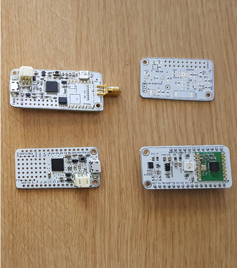
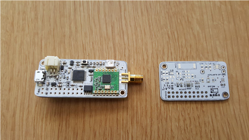
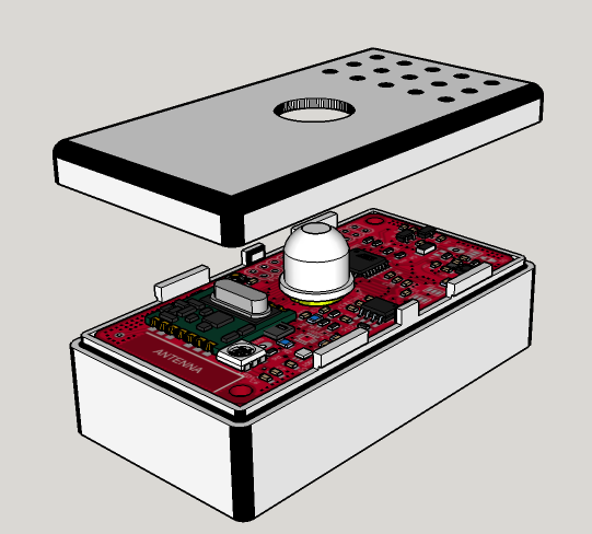
      I am enthousiast to show you my very new project : my low power multisensor for light loads.
      My roadtrip in the lowpower jungle world.

      0_1453902208486_2016-01-26_22-30-12.png
      0_1453902248527_2016-01-26_22-29-21.png
      0_1453902277215_2016-01-26_22-27-16.png

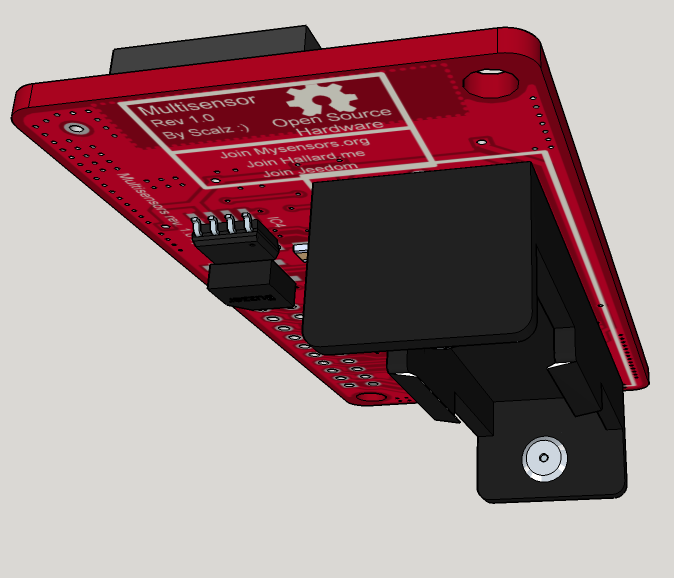
      I wanted to make an update on my other "mytinycamel" post, but I would like to explain my way for this board, so...Ah, and I will make it openhardware of course ๐Ÿ˜‰

      Why this board as I have already Mytinycamel in the pipeline ???

      I want to factorize some of my needs and costs (and that is not a question of me only, I have family, friends..which want my boards too, so why not make it the best I can). I need to have in each room, at least or optionnally, one :

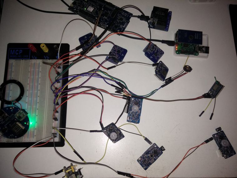
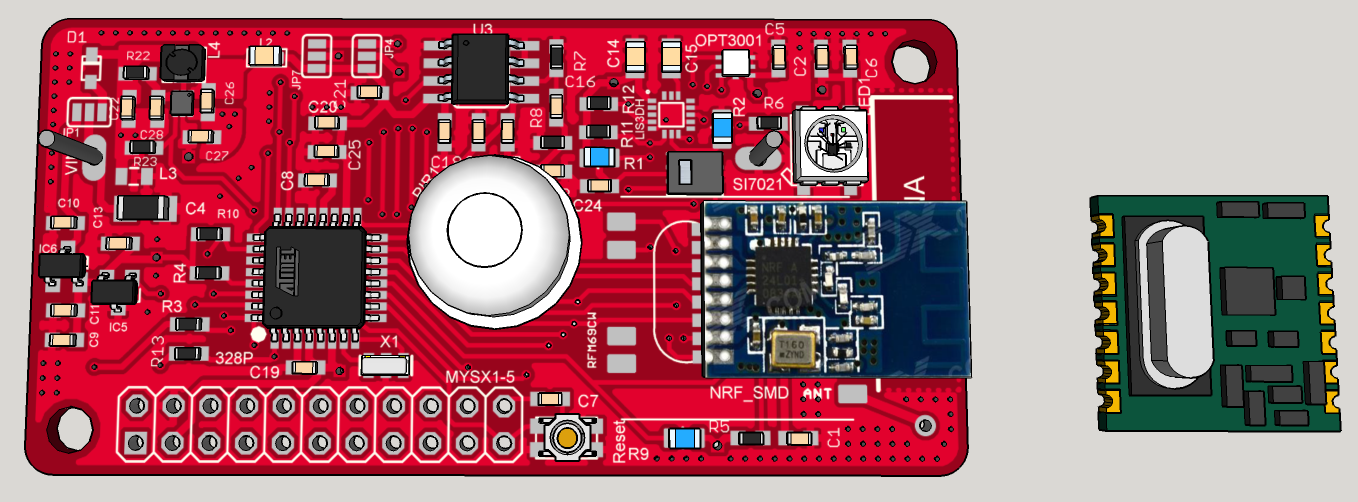
      1) We are here for Sensors :

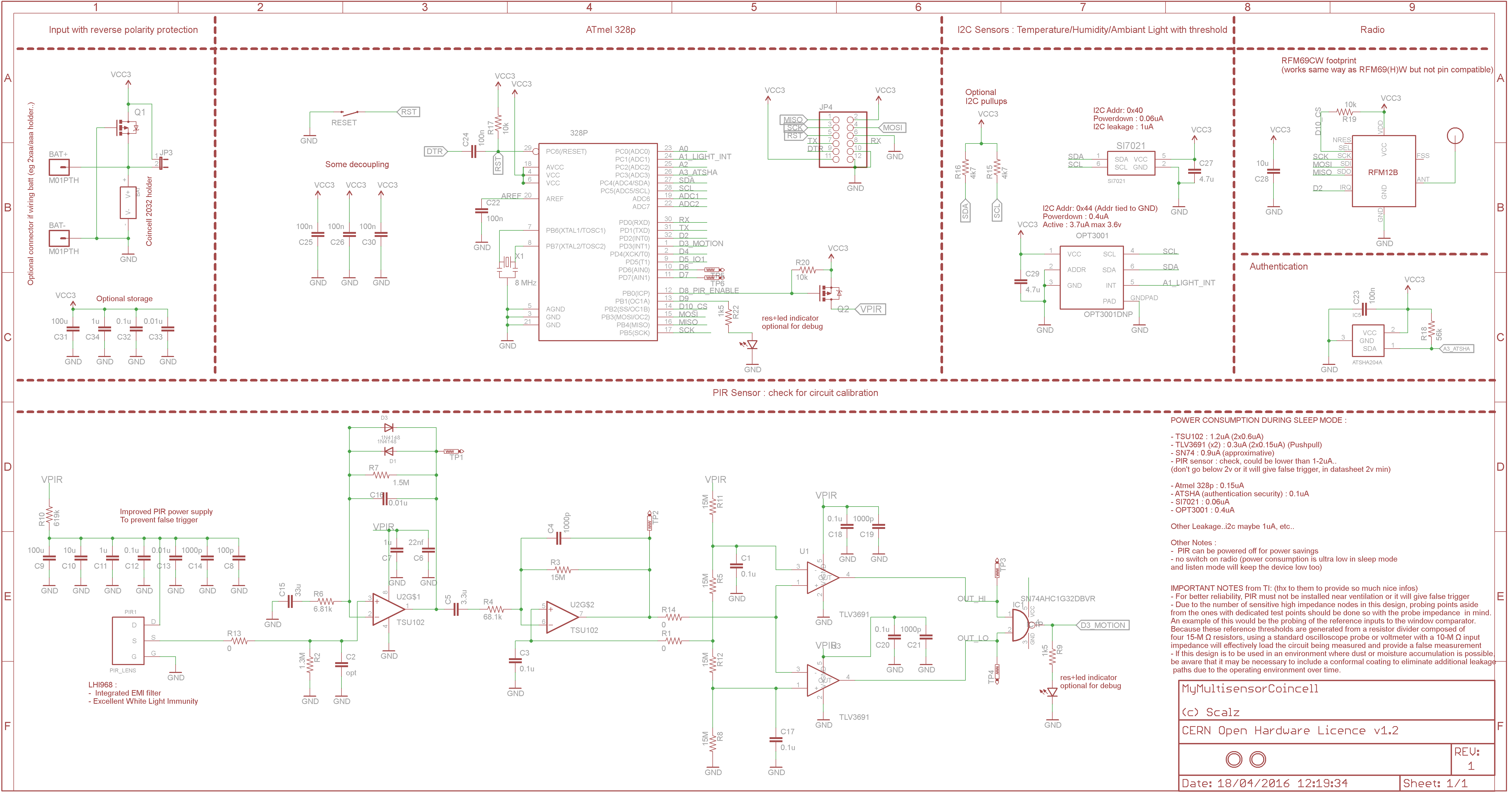
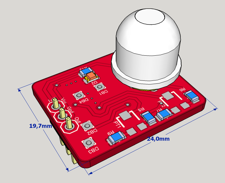
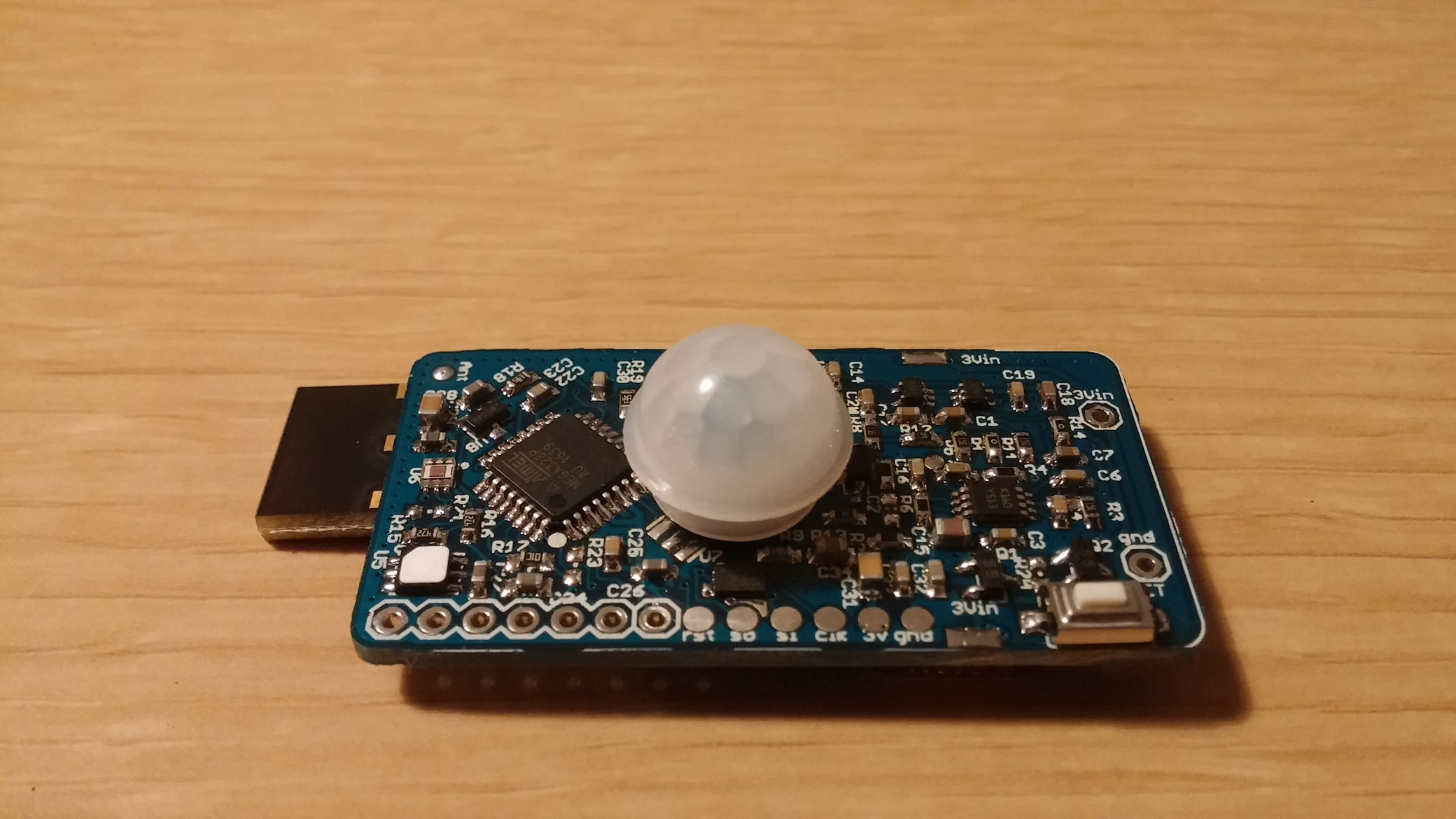
      • PIR motion sensor : LHI968 + e931.96 ic (integrated LDO and autocalibration for common PIR sensors)
      • temperature/humidity sensor : SI7021
      • ambient light sensor : OPT3001
      • Accelerometer (why not for antithief) : LIS3DH
      • a reed switch for the door
      • a buzzer (why not, for fun, optional)
      • indication led : for the moment, ws2812b

      As you can see, I have choosen all these sensors for their cost/ultra low powermode. You can find better IMU but >6โ‚ฌ (it is for antithief, so I don't need a 9DOF!)
      WS2812b, buzzer are on an enable/disable power rail, so in sleepmode I will disconnect it. Ambiant light OPT3001 is interesting too. You can set by i2c, light thresholds and trigger an interrupt on your mcu which is in deepsleep. Could be useful in some scenario.

      my first problem is about PIR motion sensor ic, it needs 2.6V min. And Mytinycamel concept is based on a 2Vto3V variable vcc.

      Humm..That is why I have designed this board. I want something the most low power I can, and 3V constant (2.7V min). Go to switching regulators, not powering it off like with mytinycamel.

      2) DC step-up switching regulator : TPS610981(x)

      This one rocks, it's a "pรฉpite". French revealed (maybe my bad english too lol), I say this when I like it and compare this to a gold nugget ๐Ÿ˜‰ I have digged digged in the river of the lowpower, yeah:) lol I hope your are laughing of my bullsh**, because I can't stop!

      Unfortunately, this ic is not handsolderable. I will use reflow process. But I am already making a rev1.1 with a crazy SOT23 buck ๐Ÿ˜‰ more friendly, but a buck is not one 1.5V cell, it would need 4x to get same result ๐Ÿ˜‰

      Common switching reg (stepup or buck) are not very efficient at lights loads (like 10uA, during sleepmodes..). And they use few or more uA in quiescent current Iq. All uA added, will be increased due to efficiency.
      My choice is : for controlled light loads, I go to stepup, and for bigger loads a buck.

      Shortly, its specs :

      • 0.7V min voltage, so you can get every drop of one 1.5V AA/AAA ๐Ÿ˜‰
      • Ultra low Iq, 400nA
      • 80% efficient even at 10-15uA!
      • two power rails (in datasheet lot of interesting variant).
      • now crazy thing, first you have bypass mode (if vin>3V for the 3V variant, vin is directly connected to vout), and then 0.7-3V vin -> 3V vout. Now if you want to disable the stepup, it goes in low powermode, which means the power rail nยฐ2 is disconnected, but power rail nยฐ1 still remains at 3V in ultra low Iq of 400nA, 80% efficient! So it's possible to cut off things with vout2, and have low power light load things on vout1.

      that's like pizza, I want the complete. ahah, really cool, isn'it ?

      now, its cons are it is not friendly to solder, and it is 2x50mA max. But we must do things smart..

      3) A little word about batteries, energy harvesting..
      I have thought a lot about this, read lot of interesting design notes. I think it's a lot a matter of taste but :

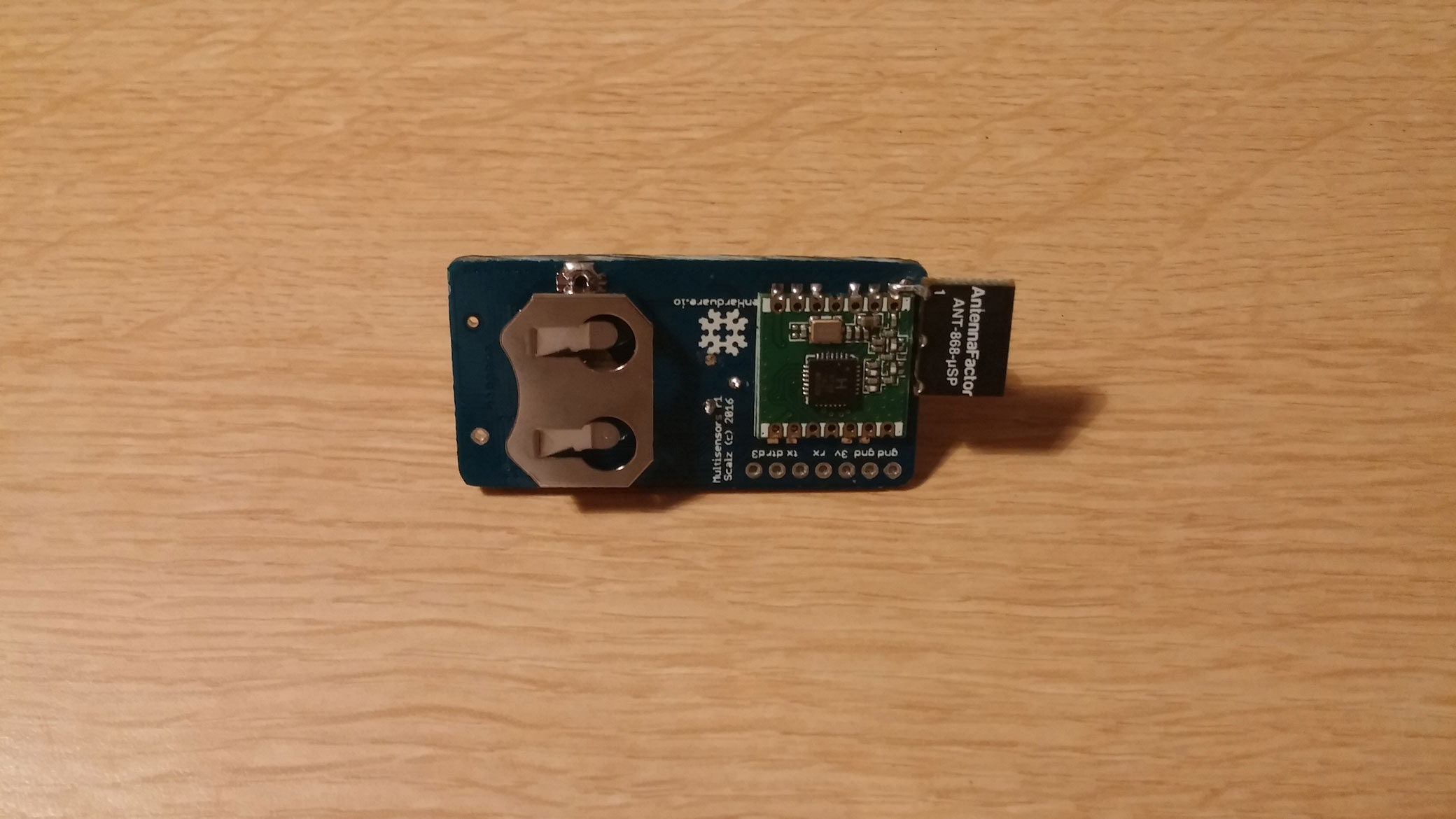
      • 3V coincell. Interesting, but not enough if I want to use RFM69 (Tx mode is a eater). It could be interesting used in a solar harvesting extender mode. But it would increase my cost, and I think I can last very long time how I will do, and for the use I need; and for the cost... And solar require some placement, which is not really the best usecase for this node.
        But it is thin, so I don't forget it, it can be cool too.
      • 1.5V AAA not bad, thin, 1200mAh. definitely not bad compared to coincell. I like it ๐Ÿ™‚
      • 1.5V AA 2500mAh alkaline, 3000mAh. That IS Cool !! You have always an AA or AAA somewhere and here we go!
      • 1.5V LR14 : 8000mAh. Wow! If I have place, like at ceiling edge, sure I will use it.
      • lipo. definitely not interesting for this node. Too bad selfdischarge rate. can vent.
      • Same thing about phone battery. not available everywhere, how long time for a model, can vent too, and self discharge is not the best. maybe 2years with no load. I don't imagine with a load..Compared to primary lithium which is 10years min theoretically...
      • rechargeable lisocl2. interesting too, but not available everywhere. Expensive, need a buck, ...

      As you can see, I am searching for less maintenance (less battery replacement...), cost and availability. So ok a booster is less efficient than a buck, but with a buck you can't use only one AA/AAA, hรฉhรฉ! A booster is not as efficient as battery powered only, but you can have constant vcc, and use the whole battery.

      So it's my analysis, my personal interpretation from gurus of low power...maybe there are better option..Don't hesitate to tell me. I do not argue to be an expert ๐Ÿ˜‰

      My favorite config will be :

      • 1AA lithium 3000mAh
      • when I can, 1LR14 8000mAh
      • for ultra thin and I accept worse maintenance: coincell
      • try the rfm69 listenmode. one other thing why I wanted something efficient at light loads.

      I suggest you to look at oregon battery lifetime calculator on google. and you will understand with one AA of 3000mA, if I have an Iq of says 30uA at 0.7 vin (a circuit Iq of says 15uA at 3V will give us 26-30uA at 0.7v vin batt end of life so the worse case). Lifetime of the system 3years mini with only one AA ๐Ÿ˜‰

      4) Other requirements :

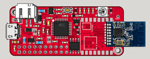
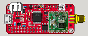
      • rfm69 or nrf24 smd for the radio

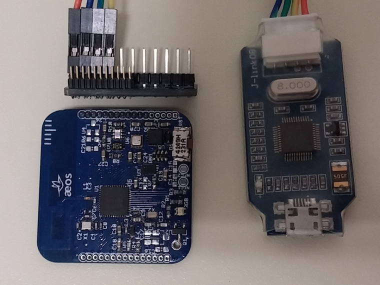
      • MYSX 1.5 Connector. That was really not easy at all to fit it!!! Lot of time, I was near to give up! But, even if I don't need it, it could be very helpful for debug. So I follow you on this @Anticimex ๐Ÿ˜‰

      • LDO SOT footprint in case I don't want to use the stepup reg.

      • ATSHA204A ic footprint : authentication (for PIR, reed switch...)

      • Eeprom for OTA. Same thing, eeprom needs to be in low power mode.

      • optional pullup for reedswitch...

      • battery measurement

      • smd jumper to choose if I want SPI bus Vcc on vout1 or vout2

      • smd jumper to choose if I want I2C sensors on vout1 or vout2

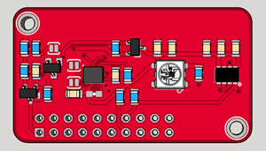
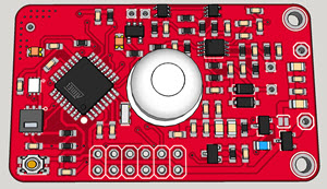
      • all component on top to boost production, or decrease cost if externally produced (we can dream!). I was not able! there was not enough space, so there is only eeprom on bottom. not bad!

      • Make the best I can for improve overall quality and reliability like
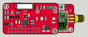
        shielded ferrite for booster
        ferrite and emi bead for booster Vout, and another one between gnd_Booster/GND
        Optional capacitor near battery
        optional capacitor near ferrite to improve emi filter
        vias on board edge and near antenna pad to improve ground
        no ground plane on one edge of the board for antenna

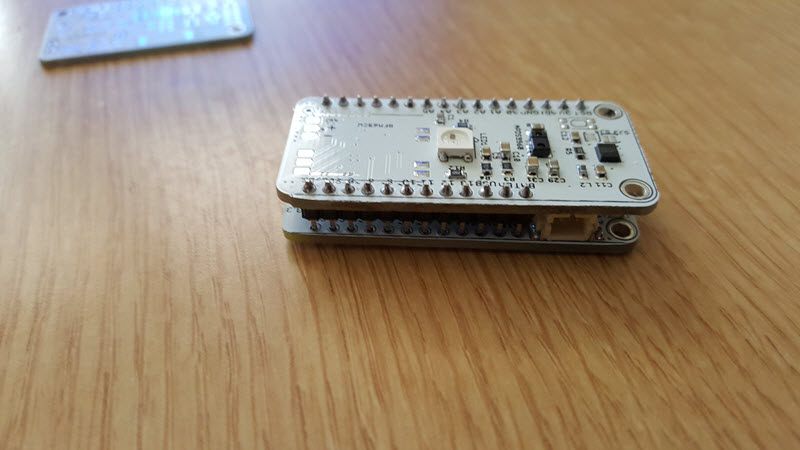
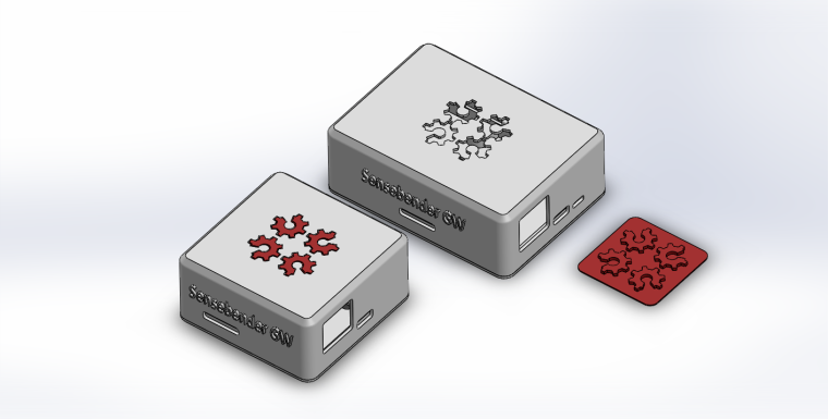
      PCB : Size 65mmx32mm
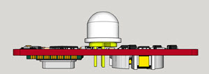
      Height of the box depends on coincell, or AA. For AA it's 22mm, compact.

      Last notes : I put this here in case you have feedbacks, or there are some infos that could help you...but It is not a noob board, sorry. Much more for reflow oven owner. How could we do to make things like this available for others??? I am thinking maybe of a simple eval board for the booster. Don't know if chinese would be interested in?
      I have not ordered yet, I am making the last decisions, but my drc are ok. cool. just a matter of time, and chinese new year now...

      posted in Hardware
      scalz
      scalz
    • RE: What did you build today (Pictures) ?

      Hi,

      today I've almost finished a speaker build ๐Ÿ™‚ (it'll be a gift for family)

      First, I would like to thx Paul Carmody who created the original design of these speakers : Overnight Sensation ๐Ÿ‘ ๐Ÿ‘
      https://sites.google.com/site/undefinition/diy-overnightsensations

      I have just changed size and format (of course I kept the internal air volume which is very important)

      1. I designed&printed a simple circle jig for my router.
        0_1515348466242_Piรจce1.PNG
        0_1515346505441_circle jig.jpg

      2. So speaker drivers can be flush on front plate
        0_1515346542637_frontplate.jpg

      3. Assembled the box
        0_1515346612578_speaker.jpg

      4. Crossover, port tube, foam
        0_1515346694824_back.jpg
        with a special place to fit some electronics like

      • rpi (for Volumio/LMS client, or a voice assistant)
      • cheap dac & 2x50w amp from aliexpress
      1. Now vinyling. I need to change these ugly black screws too.
        0_1515346789068_vinyling.jpg

      Of course, I'm too excited (and not very patient ), so I've tested how they sound... Loud! Crystal sound with very nice boomboom ๐Ÿ’ช

      Not finished, but in good way ๐Ÿ™‚

      posted in General Discussion
      scalz
      scalz
    • RE: ๐Ÿ’ฌ HALO : ESP32 multi transport GW/Bridge for Mysensors

      I know I don't give news about this project.
      So, maybe I should show you few pics, just in case.. ,)

      First, I prefer to say, we can't share code for the moment..not very release-able.

      We are using completely custom code for this project. GW code is quite big, mysensors is an experimental version (sort of "v3"). Plus for all the features, sometimes it can need some tweaks in esp32 libs etc. for the moment, sw is still tied to this project&hw.

      That said we have lot of neat stuff working, hw choices changed a bit too.

      Here we go:

      • asynchronous
      • http webserver + websocket server
      • mqtt client
      • transport bridging
      • embedded webapp for UI
      • etc.
        Well I cannot make a list for the moment, there are lot of features.

      Concept is autonomous simple network without need of a advanced controller, or when linkto/controller is down, that you can control and debug from your phone or computer. With step by step configuration, inclusion etc for easy getting started.

      Pics of the app ?? Teasing ON!
      0_1534344087554_about.jpg

      The app is realtime and very reactive. Responsive and mobile friendly. This is a single page app. written with Vue, no jquery. lightweight Bulma CSS

      0_1534344206886_home.jpg
      I started to make some widgets.. there are also multiple filters for dashboard.

      It will also be possible to get infos about network, rssi, stats etc
      0_1534344374355_network.jpg

      Lot of settings, I let you imagine them.. there are a few dedicated steps by steps too, handy for starters (like my family, friends..).
      0_1534344420975_settings.jpg

      It's also possible to see all logs, downloading them, updating app files etc.

      Teasing OFF, I prefer to keep some other nice features to show you later ๐Ÿ˜œ

      don't ask for a release date plz, we're busy on lot of projects, but we'll try to do our best! stay tuned ๐Ÿ™‚

      posted in OpenHardware.io
      scalz
      scalz
    • Sensebender/Dualoptiboot OTA HowTo in Mysensors

      Hi.

      Here is an howto about OTA in Mysensors I made for jeedom french users when Mysensors 1.5 was released. So I translated it if it can be useful to you. Things should not have changed a lot I think. I have no time for the moment to check everything. So if you note differences, tell me here and I will update. I will update pics with latest revision of the software.

      OTA, or Over The Air, lets you upload your sketch without ftdi, it's done wirelessly. Can be useful if your nodes are not accessible or you need to make signing changes for instance. To get this nice feature, you need to burn a dedicated bootloader.

      In Mysensors, we can use two kind of OTA:

      • 1st option : MYSBootloader, created by Tekka from Mysensors Team.
      • 2nd option : Dualoptiboot or if you prefer Sensebender Bootloader (in Mysensors boards). But in this tutorial I will name it "Dualoptiboot". It comes from Lowpowerlab.

      Difference between these two methods (updated from Tekka post http://forum.mysensors.org/topic/3453/mysbootloader-1-3-pre-release-myscontroller-1-0-0beta/9)

      • MYSBootloader does not require external flash: OTA FW updates are transmitted offline, i.e. MYSBootloader communicates with the controller and receives new FW which is directly written to MCU, once FW is transmitted and CRC verified, MYSBootloader hands over to the new sketch/FW.
        Pro: recovery OTA possible, also with a faulty/buggy sketch (if sketch freezes, watchdog resets and MYSBootloader takes over), no external flash required
        Cons: Radio specific, i.e. different bootloader for RF24 and RFM69 radio (rfm69 work in progess) necessary, offline (no sensor data processing possible during ota).
      • Dualoptiboot requires external flash: OTA FW updates are transmitted online, i.e. while the node is active. Once all FW packets are transmitted and CRC verified, the node reboots, dualoptiboot copies FW from external flash to MCU and hands over to the new sketch/FW.
        That means too that you need to ftdi upload your node sketch the first time or ota won't work yet as it is handled in the sketch.
        Pro: Radio agnostic (no radio specific code in bootloader so can be used in different scheme/protocols..), online (while node processes sensor data)
        Cons: Faulty FW (e.g. freezing sketch due to bad coding) cannot be recovered OTA => recovery via serial port necessary, external flash required

      This tutorial is only for Dualoptiboot Bootloader, because I have not seen an howto for this option here yet. But some parts/pictures of this howto can be used for MYSBootloader upload.
      If you want to use MYSBootloader, howto is here: http://forum.mysensors.org/topic/3453/mysbootloader-1-3-pre-release-myscontroller-1-0-0beta/9

      By default, Dualoptiboot bootloader is 8Mhz Internal + 1.8V BOD.

      What do you need:

      • SPI eeprom, jedec compliant, like AT25DF512C-SSHN-B. For other eeprom and compatibility, you can check this post https://forum.mysensors.org/topic/3160/ota-flash-types-for-mysensors
      • for evaluation or some diy projects, I did this evalboard https://oshpark.com/shared_projects/m5Uugjx5 or you can find it on opensourcehardware. No need of course if you have a sensebender, moteino etc as eeprom is already there.
      • I use an USBASP to burn the bootloader
      • I use AVRDUDESS : http://blog.zakkemble.co.uk/avrdudess-a-gui-for-avrdude/ for fuse
      • arduino 1.6.x
      • Mysensors 1.5.x : http://www.mysensors.org/download/
      • MYSController : http://www.mysensors.org/controller/myscontroller
      • So in Arduino Ide, now you shoud see Sensebender Micro board in Boards\tools

      Burn Dualoptiboot in your node

      To keep things simple, or maybe not for others..imho it's so easy with a cheap usbasp (just few wire) than arduino as isp.

      What looks my usbasp (clone, USBASP 2.0 LC Technology) and connections to your arduino or node.

      0_1458993268264_737420usbasp.png
      Wiring on nano/micro/328p:

      MOSI : D11
      VTG : VCC 3.3V
      GND : GND
      RES : RESET
      SCK : D13
      MISO : D12
      

      Once it's wired, burn fuses with avrdudess. Here the conf:

      0_1458993338862_281987avrdudess.png

      Note : even if my usbasp is a clone, I choose genuine usbasp in the listbox.

      Just click on Write in "Fuses&Lock bits" section. Then read it to check fuses are well burned.

      Now don't disconnect your usbasp.

      • Go to arduino ide, choose SensebenderMicro, Processeur Atmel328 8Mhz, serial COM port, and USBASP programmer.
      • Click Tools\Burn bootloader. You will get few SCK warning but that's not a problem, it's because I have an usbasp clone.
        Note: you could use avrdudess to burn the bootloader too.

      0_1458993400230_236880arduino1.png

      0_1458993479899_889671arduino2.png

      Yeah, our OTA bootloader is burnt ๐Ÿ™‚

      In sketch

      To enable OTA in your sketch, you need to add

      #define MY_OTA_FIRMWARE_FEATURE 
      

      or uncomment it in Myconfig.h

      OTA management is completely transparent. Everything is well handled in process() and wait() methods (when you do a gw.wait or mynode.wait for instance...)

      Important note :

      • Don't forget a sleeping node can't receive an OTA. You can wait after wakeup for instance to see if you have somethings coming or I have not tried it yet but it seems now in mysensors libs there is smartsleep() wich manage the wait() after wake up.
      • when you upload the new sketch, it is done during runtime, so you have to handle/optimize this in sketch. The best is if you detect an OTA msg, to pause process or sensors readings during the process or it will affect the speed of the OTA. I mean for instance if you read sensors, sometimes there are some delays in libs, all these things will delay ota or timeout it during main loop. Plus, if these optimization are not done and you run on battery, the longer time in TX/RX radio for the update, the more battery energy wasted. OTA can be fast 15-30sec if nothing slow it, or x minutes if not optimized ๐Ÿ˜ฎ
        So it's up to you to manage this, use non blocking/asynchronous code. The rest of the process is again completely transparent. Great!

      How to upload a new sketch just with OTA

      For this I use MYSController. It's not an .ino file that you will upload but the .hex one. So to easily get this file:

      • In Arduino ide, go to File\Preferences, on bottom click on preferences.txt. It opens preferences.txt.

      0_1458993573312_121153arduino3.png

      • Keep this file opened and close arduino ide (otherwise your changes will be erased).
      • In preferences.txt, at the end, add this
      build.path=C:\Arduino-Output\
      

      or another preferred path. It will be there you will find your .hex compiled sketch files.

      • Open arduino ide and compile/check your node project. You should now see your compiled files in the path you have set.
      • Copy the .hex to Firmware path of MYSController

      Launch your OTA update

      • Launch MYSController and in Config/Serial, check the right serial com port.
      • Click on "Refresh FW repo" so you can use your new .hex file.
        Note : When I tested this it didn't work for me so I needed to do this
        In Firmware folder, edit firmware_config.csv and manually add your .hex. Here an example where I added a Humidity .hex file for tests.
      Type,Name,Version,File,Comments
      10,Blink,1,Blink.hex,blinking example
      20,TimeReporter,1,TimeReporter.hex,TimeReporter
      100,Sensebender Micro,1,SensebenderMicro.cpp.hex,Sensebender Micro
      110,Sensebender Blink,1,SensebenderBlink.cpp.hex,Sensebender Blink
      120,Sensebender HumidityTest,1,HumiditySensor.cpp.hex,HumidityTest
      
      • Now to wirelessly send your new sketch to your node, simply right click on the node you want to update. For sleeping battery node, choose "Battery powered Sleeping". So when your node will wake up, MYSController will resend the update. Awesome!
      • click on Assign FW,
      • choose the sketch

      and voilร ! OTA should start, and then your node will reboot.

      0_1458993734904_399014arduino4.png

      I hope to have not missed something important. Please tell me, and I will add in this post.
      This howto was made some months ago, so I'm note sure if it's exactly still the same, but that should be almost ok. Try and test ๐Ÿ˜‰ and tell me. I hope it will help at least, as it is something often asked..If all is ok, don't hesitate to put it on a better place (I'm not sure if it's the best place here)

      Enjoy!

      posted in Hardware
      scalz
      scalz
    • My other PIR multisensor, on coin cell

      Hi ๐Ÿ™‚

      I will show you here a board I have roughly drafted last night (one night=one board lol ๐Ÿ˜Š ). I was bugging on something and wanted to distract my brain with an other thing..and it was too long time that doing this board was tempting me!

      Briefly the context:

      • I have already done a multisensor with PIR on one cell with booster:http://forum.mysensors.org/topic/2951/my-mysx-multisensors-board
        Not released, because I need to fix few things in my files (like maybe remove the ws2812b led which doesn't work well for me at 3v, 8Mhz. Works ok at 16mhz..and few others things). The PIR controller, here is too much exotic, to be a durable sourcable solution. I have enough of these PIR ic for me but not enough for family, friends...
        The new board, presented here, will follow my custom box.
      • I have already made an eval board for PIR which needed some tuning, based on discrete components, no exotic chip: http://forum.mysensors.org/topic/2387/low-power-pir-breakout-board-for-mysensors-and-evaluation
        Based on ST AN4368 app note.
      • and some time ago, I felt in love with this design note from TI, http://www.ti.com/lit/ug/tiduau1a/tiduau1a.pdf
        This design note is a POC for a 10years PIR on coin cell! I felt so in love that I have almost designed an eval board for this crazy CC1310 mcu that I absolutely want to try since so long time (yep, there is RF, but like some people says, read books and follow the 5 master rules, btw I have a spectrum analyzer, not a network one unfortunately! will see what I get. I know I'm maybe too much geeky ๐Ÿ™‚
        So, this design appnotes uses the CC1310 which is a very well optimized mcu with optimized power domains for sensors and RF. With a well written software, they get this excellent result of theoretical 10years.

      So, what if we applie these two appnotes to our favorite 328p mcu?? And my board was born ๐Ÿ™‚ My first coincell multisensors board (never say never!).

      First, the schematic ๐Ÿ˜‰ I will send it to fabhouse at the end of the week end, to let me more reflexion and see your feedback:

      0_1464434489502_sch.png

      Very basic, isn'it? You see, here, I'm taking another direction:

      • direct battery, no regul so 3.3V max.
      • coincell holder footprint, and two pads to connect a 2xaa/aaa holder for instance to extend the maintenance. This devices, coincell, is designed to be slim, so I would go for aaa lithium.
      • Sensors : the well know SI7021 temperature/humidity, OPT3001 for the light, LHI968 PIR
      • The PIR can be enabled/disabled, thx to a pmosfet
      • Authentication (ATSHA204A signing)
      • Radio : RFM69
      • no external eeprom this time, I will use MYSBootloader on this one
      • debug points for PIR circuits, no potentiometer, I will make it at hand, fixing parts values.
      • reverse polarity protection

      Important note : if you want to take this schematic and make your own...I hope you will take care of the routing on the PIR part because it's very important (false trigger is not far..). This part will, I'm almost sure, need some calibration. Maybe some caps could be removed but for proto I prefer to keep them. Plus it helps for reliability.

      About power consumption:

      You can see on the schematic few notes about this, this should give us, perhaps, roughly, 5-6uA in sleep mode with PIR enabled. No need to disable the radio (it's a camel in sleep mode + i plan to use the listenmode).

      • Few simple maths because it can vary with PIR trigger, coincell quality: but for a coincell of 230mAh, I plan for 200mAh usable energy. Sleep mode :5uA, 30mA in radio transmit during says 40ms (can be more time with signing...), 10 wakeups/hour. That gives us a theoretical estimation of 2.33 years. Not so bad..It can be more if you disable pir for some periods,or less if bad software..
      • that will need some software to improve the sleep mode, blind time, low power during blind time and retrigger..nice challenge ๐Ÿ˜‰

      Few 3d previews, size is 49x30 (so 3 boards on a 10x5cm or 6 on a 10x10, 2mm for vcut)

      0_1460207032902_2016-04-09_14-42-35.jpg

      0_1460207042832_2016-04-09_14-43-18.jpg
      Slim ๐Ÿ˜‰

      One question do you prefer to have PIR High and low signals directly connected to atmel inputs, or like maybe I do, use a nanopower OR gate for one input???

      If you have any remarks, I will be very happy to make some changes (basic) before ordering my pcb. Does it sound good to you?

      Humm, I'm not sure, but @Samuel235 you have here an example of mosfet use to enable power if you want.

      See you soon ๐Ÿ™‚

      posted in Hardware
      scalz
      scalz
    • RE: What did you build today (Pictures) ?

      That was yesterday.. ๐Ÿ˜Š

      @tekka and I tested some new features he made, so here was my humble and fun test setup

      0_1510566539991_IMG_20171112_203729.jpg

      Of course the Halo GW didn't disappoint us! All boards (mixed mcus and radios nodes) were attacking it at an agressive rate (100ms rate), and there was no crash at all. Halo GW was laughing & kidding us saying "Please give me more, I like doing this" ๐Ÿ™‚ (but I was lazy to assemble more, there was 13 nodes on the table..).
      Too strong @tekka ๐Ÿ˜‰

      posted in General Discussion
      scalz
      scalz
    • RE: ๐Ÿ’ฌ Sensebender Gateway

      Tea time..

      Here is my custom box for your RFM69 Sensebender GW ! Beautiful board though ๐Ÿ˜‰

      No nail no screw ๐Ÿ™‚

      0_1486052016552_Custom box for Sensebender GW.jpg

      0_1486052034817_Plate for Sensebender GW.jpg

      0_1486052057656_Bottom plate for Sensebender GW.jpg

      Last final minor check and i release the files, sure! (i've done one for nrf too in case..)

      posted in OpenHardware.io
      scalz
      scalz
    • Low power PIR breakout board for Mysensors and evaluation

      Hi,

      I like to make my boards small as I can (with my "little" knowledge, lol) and, like lots of you I needed a small, slim and of course low power PIR sensor. I don't like chinese HC-SR504 board because there are big capacitor on it. Not easy to integrate in small enclosure. So I decided to re-design this chinese board with smd capa.
      But, Anticimex pointed to me a very interesting app note : ST AN4368. Thanks to you @Anticimex for your valuable advise ๐Ÿ˜‰

      Note : I ordered pcb few weeks ago, it should not take lot of time now to get them. I ordered it at oshpark, as board is small, price is cheap.

      So this board is based on this ST appnote, and especially on the first schematic in it (based on TSU104 opamp, more low power).As app note state, it should be somewhere 23uA. I am using a nanopower nand gate. I didn't find better for this ref..so the board should be 1uA more. I hope it will stay between 23-25uA which is not bad I think..

      I have made few changes for easy testings:

      • 2x potentiometer added
      • debug points
      • optional led on Out Signal (for debug)

      Size : 24x19.7 (mm)
      Components size 0805.

      Now some screenshots:
      3dview.png

      https://www.youtube.com/watch?v=Lc4ZXmKnMNw

      Boards can be ordered here : https://oshpark.com/shared_projects/Dc6Tlrt1

      Eagle files and BOM on my git, here : https://github.com/scalz/MySensors-HW/tree/development/LowPowerPIR_Breakout

      So it should work, as I followed app note. Changes I made are minor. And I have taken care of routing to try to not have problem on analog trace...

      Enjoy!

      posted in Hardware
      scalz
      scalz
    • RE: MySensors vs Zigbee

      @alowhum said in MySensors vs Zigbee:

      It would rock if the NRF24 that it uses for MySensors could somehow also do Zigbee at the same time. Sharing the radio. Would that even be possible? Or does MySensors 'hog' it?

      Zigbee is an open standard (and since recently so is Z-wave), so in theory implementaton should be do-able..

      Yes it would, but I don't think you'll see it soon (>months), and not with nrf24..
      Like I said previously, this imply "some" hardware and software changes, not very backward compatible, so that's not a very top feature in todo (the native zigbee/mysensors bridge) even if we already talked about this for fun ๐Ÿ˜‰ There are others things to improve imho..

      @fhenryco said in MySensors vs Zigbee:

      More specifically, what was the point to develop the mysensor protocol when BLE is available with very low cost modules (which is not the case for zigbee in general much more expansive) ?

      I don't know exactly about MySensors roots (I wasn't there), but it's good to remember that MySensors focus always been on simple hardware in arduino for beginners like 328p, nrf24 etc. so far.
      And you can't run BLE stack on all kind of hardware. BLE for example has a heavier footprint than MySensors (and zigbee too) and needs more resources.

      Is it that BLE is constrained to remain on 2.4 GHz when mysensors protocol can run on many frequencies kind of transmitters ?

      Yes, even if at the beginning MySensors was 2.4ghz only. Lot of people use it for sub-Ghz (433,868 etc).

      Is it that mysensors can be even cheeper ?

      This depends on your project.

      As far as i have understood a similiratity is that both are not IP based nor mesh protocols.
      BLE is a much more complex protocol up to the application layer however the success of mysensors in the DiY community seems to imply that much of the extra offered capabilities by BLE (security?, complete endpoint identification to the network?, network management capabilities? ) are of little value for most domotics applications ...(?)

      Yes BLE stack is more complex. And in some case you can run less nodes in a network than MySensors. That depends on implementation, manufacturers etc.

      MySensors can be as secured and more.. Imho, regarding security, I like the idea to use proprietary protocol, for example in 2.4ghz like MySensors, than BLE which is compatible with phones. I prefer to use a gw..Especially for HA, as in general, we use advanced controllers. Of course, it depends on your project and needs.

      You can easily access to the MySensors stack to make any change..
      For example, easy to say this stack or this one is now open source, less fun when you have to dig in sources ๐Ÿ˜‰ always the question of is it worth it? why? as a dev do we really need it, or is it just for challenge but waste of time as there could be others priorities? what are the compromises, pros&cons etc.

      Or may be it's just that BLE is not designed to allow the BLE nodes to declare themselves to controllers such as domoticZ , ...

      That depends on the controller used, sometimes you're limited to a type/brand of devices. You can also tinker with nodered as proxy.

      Finally:

      • if using zigbee or BLE, what would you miss?
      • if using MySensors, what would you miss?
      • and if the point is just about some sort of universal compatibility, to have possibility to buy cheaper hw, then is ROI worth the effort? Couldn't it be solved with nodered? etc

      Recently @yveaux showed us this cartoon. I think it fits well here ๐Ÿ™‚

      0_1531838071661_standards.png

      Sometimes, proprietary stuff, or standards, can be a business source too.
      I can't disagree with you, it's too messy ๐Ÿ™‚

      posted in General Discussion
      scalz
      scalz
    • RE: ๐Ÿ’ฌ MyMultisensors

      Yo,

      for those who have not seen my latest rev..apologize, I'm working hard to release all my stuff ๐Ÿ˜‰
      It's still working well btw. this is the revision i will release i think (i have few other nice iteration but that's enough!).
      0_1474116844076_20160915_212045.jpg
      0_1474116860159_20160915_212143.jpg

      • Size is 25mmx49mm (same size as a nodemcu)
      • Same specs as before, plus OTA. So optimized for very low power and coincell management. Temp/hum/pir/lux/contact door input
      • Thickness depends on the battery used. That's great as now it's possible to use different kind of battery holder ๐Ÿ™‚ CR2032 for the thinnest (8mm without PIR) very thin!, CR2450, or through hole 2xAAA holder
      • you can see a test I want to try: a special antenna i saw on the forum. I will compare it with straight wire antenna, and coiled wire antenna.

      See you soon ๐Ÿ™‚

      posted in OpenHardware.io
      scalz
      scalz
    • Roller Shutter

      Hi,

      A friend asked me if I would be able to make a RollerShutter node which could open/close his roller shutters 0-100%. Yeah, new challenge for me! I am happy to share with you my work ๐Ÿ˜„
      Another thing, the board can be used as a simple relay board of course ๐Ÿ˜‰

      Note : it is still dev, even if I have successfully debbugged my previous revision of this board. But I have not ordered yet this new one. As I have made some changes, I am still afraid to have a small hidden mistake, lol. That is why I say this but I have hope. And I will update this note when I will be 100% sure!
      There are some people who will order pcb and help me to betatest this board. Thanks to them and for their advice too (I am thinking to @Fabien, and some jeedom users.)

      Ah, of course, I would be very happy if you have any feedbacks, remarks about my schematics or layout. I'm not an electronician ๐Ÿ˜‰

      How is Rollershutter motor controlled:
      On-board, there are 2x10Amp Relays. Rollershutter motor don't use 10Amp of course, nor 5Amp. So maybe if relays are 10Amp rated, no need of snubber (I hope). If needed, it should be external, there is no enough space onboard.
      That said, for a simple relay board too, you can control lot of thing with 10amp.
      So, we have 2 relays, for a rollershutter:

      • 1x NO : which enable/disable power on the second relay. It is like "Stop Motor".
      • 1X NO-NC. you can toggle it, and drive Up, or Down the rollershutter motor. Remember this relay need to be enabled by the previous one.
        So relays are "interlocked", you can't enable "Up" and "Down" outputs to motor at same time and burn your motor.

      How to open/close 0-100%

      • We need to know the up and down ends. It is managed by the onboard ACS7125 sensor. It senses motor current flow and we read it with ADC on arduino. So when motor is active, we have a power consumption.
        When an up or down end is toggled, the motor stops (because of mechanical switch...). So there is no power consumption. So you can see, with ACS712, we can know in which state we are. We are able to read some kind of power consuption curve too if needed and no mechanical ends switch available..
      • We need to know how long it takes to open the rollershutter, and to close too (it may be not the exact timing open vs close time). So, here it is a story of millis chrono, taking some sample, making average etc...software stuff
      • good care of states in the sketch. no loop inside to not block anything, etc...

      General specs (also visible on my github) :

      • Components size 0805. Board size 47*48mm.
      • Can drive 12V up to 220V motors (for 12-24V just connect power source to PWR connector, for 110-220V connect one L connector to PWR connector)
      • AC/DC step down 220v-5v
      • 2x10amp relays, G5Q type, 1xNO, 1xNO-NC
      • ACS712 0-5A current flow sensors
      • Inputs for UP, DOWN, STOP
      • Some securities. On AC input, there are varistor+5Amp fuse. A CTN thermistor, on pcb bottom, under the AC/DC step down, to know board temperature in case. A dual relay driver to manage relays and parasite.
      • ATSHA chip footprint for authentication
      • Eeprom chip footprint for OTA update
      • Connector for ftdi
      • Connector with AVRSPI, I2C for external breakout (tactile switch, gesture...), 2 available I/O (D3 int, D4)
      • two versions : NRF24 smd or RFM69(H)W
      • Screwterminal 5mm pitch

      Here is the schematic:
      Schematic_nrf_1-1.png
      Here some pcb views:
      top_pcb.png
      bottom_pcb.png
      Some 3d views:
      top_overview1.png
      bottom_overview.png
      For fun, a first idea for a rollershutter custom box, with holes on cover for luminosity+gesture
      https://www.youtube.com/watch?v=bKaH_GUuFAI

      Sketch
      Sketch is almost done but not tested yet. I will post an example soon, before I need to clean and update it as it was for my previous rev.

      All my files (including gerbers) are here : https://github.com/scalz/MySensors-HW/tree/development/RollerShutterNode

      Important
      **Note **: it is a project in progress. I repeat it just in case lol. It is hobby, opensource, and I share the little time I have for this with others projects in progress too. It costs some money of course, we are all in same boat with diy. So all these parameters can make the project longer. Very sorry for this
      But all the stuff is almost done. It just need to test now!
      Note 2 : As I said, I debugged my previous rev. All seems good, but I don't want to say it is a stable version until I am 100% sure.

      Thanks for all your feedbacks.

      posted in Hardware
      scalz
      scalz
    • RE: ๐Ÿ’ฌ Carte Fil Pilote MySensors NRF24L01

      Hey guys!

      If you can try to keep things in English, that would be great!
      for Mysensors creator at least ๐Ÿ™‚ and the rules paragraph 6 https://forum.mysensors.org/topic/610/forum-user-guidelines
      And also because that looks messy..

      I know there are no sub language forums and i don't know if there will be, but don't show that French are english lazy! No shame lol
      I'm french too ๐Ÿ˜‰ Imho i prefer english, because it's more universal for sharing.

      I'm not big fan of translating foreign language i don't know..so if there would be sub german etc.. i would never read it, no time to spend with google translate. So i could miss nice stuff, or little nice tips in comments. Plus trickier moderation i can imagine.

      I hope you understand. For the moment it's like this, who knows in future.

      Translation in french..

      I'm joking ๐Ÿ™‚

      posted in OpenHardware.io
      scalz
      scalz
    • My first multisensor daughter board

      Hi!

      I am happy to present my first daughter board for MyTinyCamel (my other board in progress).
      All this work is in progress, but I like to share my work and it was rather lot of work ! but I think I will have something small&modular finally ๐Ÿ˜ƒ

      I have made another version of MyTinyCamel with onboard sensors, but what about if I need a PIR sensor, or a gesture sensor. and want to keep things small. So I made this little daughter board.

      multisensor_dboard.png

      And a small vid to see how it looks with MyTinyCamel and 2xaaa:
      https://youtu.be/4ULY3P-F-Fo

      Technical descriptions (all optional):

      • 0805 NTC thermistor for temperature
      • SI7021 : temperature and humidity
      • BMP180 : pressure, barometer
      • VEML6070 : UV
      • TSL2561: ambiant light & IR
      • APDS-9960 : ambiant light & RGB & Gesture
      • PIR motion with mini lens (schematic is based on HC-SR501), with H-pad & trimmer footprint for sensibility
      • PIR can be enabled/disabled by onboard mosfet on daugther board
      • enlarged footprints for sensors (I hope to be able to handsolder them by adding a small drop of paste and heating the pad, otherwise I will have to build a reflow oven...)
      • solder jumper for each sensor to choose : VCC3 from MyTinyCamel or VCC_Sensors from Mytinycamel by mosfet

      There are 2 footprints for PIR. Why? because MyTinyCamel can have RFM69 or NRF24 smd. When nrf24 is used as you can see in the vid, it is a little wider. I wanted PIR sensor centered on top of a custom enclosure, in each case, so...

      Some notes :

      • as it is small, you can't use Gesture chip and PIR motion in same time. it is selectable by jumper. This jumper let you use : PIR or Gesture or External IO (smd pad).
      • When Gesture chip is soldered (APDS-9960), the onboard mosfet is used to enable/disable the internal IR led of the sensor. But it can still sense ambiant light by its VCC.
      • if it works well, I will make another version of this daugther boad for @Anticimex motherboard. I have thought a lot about I could make this compatible but I needed to stick to MyTinyCamel for this rev...

      I ordered one set of board to see, at oshpark... But your feedback are welcome of course, as now I need to design a small custom enclosure for this..

      And it gives me lot of other idea, like a micro-usb connector for usb powered or Hi-link AC-DC step down for something in wall mounted...

      See you soon!

      posted in Hardware
      scalz
      scalz
    • RE: ๐Ÿ’ฌ Sensebender Gateway

      Little gift.. ๐Ÿ™‚

      Custom box for the NRF non PA version:

      0_1486135733912_20170203_161524.jpg

      0_1486135777240_20170203_161550.jpg
      A bit enlarged for NRF.

      0_1486135802750_20170203_162026.jpg

      And here the 3d preview for both versions with my little cheat for bicolor as i've still not added this feature to my printer
      0_1486135971628_assembly_rfm69_nrf_1.png
      You can see i've added a little slot near usb on the NRF version, it's for the leds indication in case box wouldn't be white (no need for white box, you can see it by transparency). I'll do the same for rfm69, and put variant stl with it or not.

      Next Nrf PA version, and that'll be fine ๐Ÿ˜‰

      posted in OpenHardware.io
      scalz
      scalz
    • RE: ๐Ÿ’ฌ Aeos : a NRF52 versatile, up to 9in1, device

      Here is a pic of Aeos rev 1.0. (the revision with 4layers and custom antenna for better perf, but not tuned yet).
      Working well though ๐Ÿ™‚

      0_1500930592781_20170724_225631.jpg

      With a simple adapter to my segger OB for programming it, or ftdi and some IOs. (actually playing a bit with ble for a change). Need to print a box!

      posted in OpenHardware.io
      scalz
      scalz
    • RE: ๐Ÿ’ฌ HALO : ESP32 multi transport GW/Bridge for Mysensors

      thx guys, always glad to hear.

      With this project, I don't intend to replace a rpi controller of course. I'm using one too.
      This was something I wished for a while, also wanted nice tools (hw & sw) for debugging/using lot of transports.

      But more important, is family and friends, to easily get them started in HA. I think for the moment HA still looks a bit complicated for lot of people..often making people smile or looking at you with wide open eyes.

      Heard things like : "you're a crazy geek!" , "wow..well that's cool, sure, but I don't think I need this at home, or later maybe." "nice! but what I woud need is robot vacuum cleaner" ๐Ÿ˜„ "seems complex, what about privacy, hacking", "why do you want to datalog temperature, humidity.." ๐Ÿค”

      I know lot of smart non computer people who don't have time to become sysadmin, use CLI tools, json, rpi linux, blablabla.
      Or even if everything is in place, they wouldn't have time to learn how to use controllers+UI..pity.
      Also would your wife be able to add a timer, plan an action, add a new node in network, know where to click? is it too complicated to use?! So don't ask them to setup or tune their HA with Nodered!
      In fact they are much more interested in something lean and easy to use. Like commercial products do!
      But often cloud, or chinese UI??, not opensource fw (you can't change behaviour of a switch button without a controller..) etc

      So to make this simple, my setup will work like this:

      • get a Halo GW of course ๐Ÿ˜‰ and simply burn fw with a ftdi adapter. I'll prepare it for my friends. then it's simply a matter of wireless updates. No 'OS' updates, dependancies blabla simply a small file to update by air
      • same for a node.
      • with phone or computer, go to Halo UI app, and simply follow step by steps for first setup and pairing! I'm trying to make UI very easy to use.

      That's all, you now can interact with your network! no need to setup a rpi, nodered etc..

      Finally, "cherry on cake": I made a MySensors App+skill/action for Snips

      • buy or make a Snips voice assistant
      • download the MySensors Halo App for Snips from their app market (not published yet)
      • go to Halo gw UI and setup Snips

      Voilร  you can voice control your MySensors network. Again no external rpi as controller. Only gw and snips device. Nothing complicated to use.. lean and low power ๐Ÿ€
      Once you're used to it, then you can link the gw to a more powerful controller of course. it's a MySensors gw after all ๐Ÿ˜‰
      I'll try to make a video of the setup.

      posted in OpenHardware.io
      scalz
      scalz
    • RE: Your workshop :)

      As i'm actually tidying up thing, i can show some pics where i spend some tinkering time.

      0_1494186632144_20170501_133058.jpg
      I'm planning to renovate it, because i'm also missing place for my 3d printer and some others stuff.
      There is a lathe and a drill but it's for quick hurry work, there is another room for more dirty mechanical stuff.. but i can't show you, it's dirty ๐Ÿ™‚

      0_1494186714267_20170501_133220.jpg
      My favorite tools :

      • my super mini TS100 solder iron. But if you ask me, for tiny SMD like DFN for instance, i prefer my Weller Magnastat with a 0.2mm tip. The tip is thinner even if i've bought the thinnest tip for the TS100.
      • hacked Rigol Ds1054Z. Really worth the price!
      • hacked T962 reflow oven. Very cool too (better for leaded solder though)
      • smd books
      • my magnifier of course!

      for the rest, there are also great tools like power supply, a spectrum analyzer, generators..

      0_1494187237909_20170507_213449.jpg
      My 1st 3d printer, i like it, works very well. I'm planning to build a new, bigger and enclosed one.

      Talking about soldering vise, i have this old tool i don't use it often, but when i need it, i'm happy to have it.
      0_1494187460902_20170507_212626.jpg
      I'm pretty sure this is not hard to reproduce with some T-Slots and so on ๐Ÿ˜‰

      When you have a 3d printer, this thingiverse design can be helpful, for debugging stuff, or can be used for soldering but with care else plastic would melt.
      http://www.thingiverse.com/thing:801279

      posted in General Discussion
      scalz
      scalz
    • RE: some problem in sensor + repeater !

      @Reza
      @boozz has already answered you how to. You should try, that does not hurt, and you may be happy by the result. You don't want a sleeping repeater? better a waiting repeater!
      That said i would not use the wait, it's possible to code this quicker. But it's a little bit more advanced.
      I advice you to read some reference about Arduino etc... and try. always try or you don't learn anything!
      An howto which could be useful for you, perhaps later, is the blink led without delay from Arduino Reference for instance. And lot of other things. That's not always easy to write code for others, can take time or not same config. and others don't learn then..

      posted in Development
      scalz
      scalz
    • RE: ๐Ÿ’ฌ My simple RFM dongle for Serial GW

      I have just assembled another one for a friend. Works very well with mysensors 2 ๐Ÿ™‚
      0_1468163482216_gw_dongle.jpg
      Same pcb for the two's of course, I like the rgb led with the indication led api ;):

      • on left, long range RFM95 GW usb dongle.
      • on right, RFM69 High power GW usb dongle.
      • bottom, a multisensors I have just assembled.
      posted in OpenHardware.io
      scalz
      scalz
    • RE: What did you build today (Pictures) ?

      thx for interests guys ๐Ÿ™‚
      I'm just not sure if there would be enough interest for me to produce. I've not really thought about it! It's the first board of the batch.

      I call it a premium dongle because

      • it's 4layers. It's just a little bit more expensive than 2layers. But quality is a lot increased (better impedance, full gnd plane, better routing etc). It's also recommended by lot of rf module manufacturers for topnotch perf
      • I uses the high quality BT840XE module. As you know, it's a well documented and known module, and it's CE/FCC (better, as it includes a 20dB PA).
        Actually I just use a few pins on edges, and 18 pads under it..
        I had the choice to use this module, or to design mine with a frontend, but for once, I decided to go "simple" for a quick debug. And the price difference vs homemade, maybe +10โ‚ฌ, is worth it imho, time saver, and I don't mind I just need one!

      Why did I make it? Because I can and would be pity to deprive myself ๐Ÿ™‚
      And we can have a nice and reliable dongle for the team, just in case.

      You're right I have others hobby projects, they're not dead.. ๐Ÿ˜…

      • just lost a bit of interest on Aeos release, I agree on this, because I prefer subghz for mysensors, and would like to keep 2.4 for others protocols.
      • Halo is not dead, actually it's one my favorite. I just need to find a way to include Janus in my "serverless" project which is mostly ethernet based (I made a full webapp, that I'm porting to true native crossplatform sw, android phone+tv, windows, linux, for better experience). "serverless" meaning optional rpi/computer

      Oki, I'll post others pics soon.

      posted in General Discussion
      scalz
      scalz
    • RE: Node to node communication fails if gateway is not reachable

      for info, thanks to @tekka, he prepared a PR to address node to node communication, and make you happy ๐Ÿ˜‰
      https://github.com/mysensors/MySensors/pull/1174

      So

      • you can try berkseo implementation but like I said above, maybe it will be broken in future, who knows.. as it's using internal mysensors api (not the end user api).
      • or try tekka work and feedback (from a end user point of view, you just have to add same changes in your files as those this PR) https://github.com/mysensors/MySensors/pull/1174/files

      Btw, not sure if it will work with signing (whitelisting etc), and if not, not sure when.. but plz feedback!

      posted in Development
      scalz
      scalz
    • RE: ๐Ÿ’ฌ MyMultisensors

      nothing fancy, just wanted to share how this is working as we're all busy..

      there is a small problem with my widgets but no matter ๐Ÿ˜Š I show you what this board outputs if you're curious, and I'm beginning to like this board ๐Ÿ˜

      0_1469402151633_dash_multisensor.jpg

      I will change my dashboard later, it's just for fun.

      For power consumption, few reference for sleep time : old VC506 multimeter but working well + uCurrent Gold

      • PIR enabled, other sensors+MCU in deep sleep with interrupt on pins : 4-5uA for Varta CR2032 coincell, 3-4uA for 2xAAA Duracell
      • PIR enabled, other sensors+MCU in deep sleep with interrupt on pins + WDT enabled : 11uA for the coincell, 8uA for 2xAAA
      • PIR enabled, MCU active 1Mhz, other sensors sleeping with interrupt on pins + WDT enabled : 730-740uA for both

      not that bad ๐Ÿ™‚
      I have an other proto waiting (for fun because i do not really need it lol). it's another version not for coincell, but as thin and much smaller! with ota back. I thought for coincell, ota or chain tx pulse, was a bit too much battery killer..even if CR2450 imho...and with our preferred lib ๐Ÿ™‚ there are multiple chain tx for presentation, some signing stuff etc..and you can't pause this to limit internal resisitance of the coincell..

      The sketch is still in progress. I mean it's working of course, but still looking to improve a bit things..but i can show you the infos and commands which are available for the controller. That should help to save enough power I think:

      
      // For controller. CHILD_ID are presented. CMDID are not presented to not charge radio tx. But are available from controller, using receive()
      //  CHILD NODE ID/CMD           ID    Description
      #define CHILD_ID_PIR            1     // PIR sensor 
      #define CHILD_ID_TEMP           2     // Temperature sensor
      #define CHILD_ID_HUM            3     // Humidity sensor
      #define CHILD_ID_LIGHT          4     // Ambiant light Child node ID
      #define CHILD_ID_BATT_SENSOR    5     // Battery voltage, % is reported by sendbattery stuff
      #define CHILD_ID_RSSI           6     // Radio rssi
      #define CHILD_ID_DOOR           7     // Door reed switch
      #define CHILD_ID_PIR_EN         8     // Enable PIR 
      #define CMID_FULL               10    // Command from controller with all params below in one tx. below is more for debug..
      #define CMID_PULSES             11    // Command from controller to set PIR number of pulse for windows time 
      #define CMID_WINDOWTIME         12    // Command from controller to set PIR window time   
      #define CMID_BLINDTIME          13    // Command from controller to set PIR blind time   
      #define CMID_CANCELTIME         14    // Command from controller to set PIR cancel time
      #define CMID_EN_LIGHT           15    // Command from controller to enable Light sensor threshold 
      #define CMID_LIGHT_MODE         16    // Command from controller to set Light sensor special mode (for instance, enable pir at certain light level only...) 
      #define CMID_LIGHT_H            17    // Command from controller to set Light sensor high threshold 
      #define CMID_LIGHT_L            18    // Command from controller to set Light sensor low threshold 
      #define CMID_LIGHT_DELTA        19    // Command from controller to set difference of lux for update controller 
      #define CMID_TRANSMIT_INTERVAL  20    // Command from controller to set time between sensor updates
      #define CMID_TH_DELTA           21    // Command from controller to set difference of temp/hum for update controller 
      #define CMID_EN_LED             22    // Command from controller to set led
      

      See you soon ๐Ÿ™‚

      posted in OpenHardware.io
      scalz
      scalz
    • RE: What did you build today (Pictures) ?

      This evening I assembled another dongle (and a few other boards).
      @nca78 as you asked, here is a pic during tests. Tiny dual rf dongle board, isn't it ๐Ÿ™‚

      0_1568059742404_IMG_20190909_214158.jpg

      0_1568059839548_2019-09-09_21-44-48.png

      ๐Ÿ˜Ž

      posted in General Discussion
      scalz
      scalz
    • RE: My MYSX Multisensors board

      Yep I have already all these tools ๐Ÿ˜‰
      I have already soldered 0402, for sensebender for instance ๐Ÿ™‚ I ordered 3 boards at oshpark, couldn't wait! It works well.
      But when I can, I prefer 0805, or 0603 min. My way to share. 0402, not everyone will try, nor 805 I know..! And I prefer to minimize mistake source , less small things, less error possibilities at prototyping. I could have choosed atmel vqfn too!
      I like when I see someone sharing 0603/0805 files. When I see something 0402 and really need it, I make it 0805/0603 ๐Ÿ˜‰
      For this board I think 0603 min is ok. For the moment it's 0805, I will try to add a little bit more clearance before ordering it.
      It could be a little bit smaller with 0402, but not much, there are antenna area, and battery connector, components on top... And between a 6 or 6.5cm pcb...hum is it really useful, I am far away of coincell size so! And I don't want to put radio on bottom, between the pcb and battery holder. it would add more thickness.

      Sensebender is a very special case, a challenge. It is the ultra mini sensor board. but no batt holder. Add it and a box, it's not the same size. There are minimal

      posted in Hardware
      scalz
      scalz
    • RE: Office plant monitoring

      yep, I think that would be a nice module!

      @mfalkvidd @hek I hope to not OT ๐Ÿ˜ณ I just want to show you few old school pics, a small jump back of 20years! My dad's stuff, a real maker ๐Ÿ˜‰

      This one was, I guess, the smallest soil moisture, in "virtual bulb", meaning there was no external electrodes, so no corrosion :
      0_1461316115256_2016-04-22_10-58-38.png
      2nd: still in virtual bulb, humidity, salinity, roots temperature, temperature compensated, pH tendancy
      0_1461316160275_2016-04-22_10-59-39.png
      Multi level soil moisture:
      0_1461316305917_2016-04-22_11-02-44.png
      And these old Aurel 433mhz emitter/receiver !
      0_1462008084352_IMAG0394.jpg
      I have lot of others old pics like this lol! He was selling his devices.

      Few months ago, I have started to mix some of his old project with our new techno, but not finished! I would like to have sort of flo** pow** but more professional..still open. what!!

      posted in My Project
      scalz
      scalz
    • RE: ๐Ÿ’ฌ Roller Shutter Node

      hi

      my node is still working well..i'm trying to reorganize my priority, I'm enough confident to release ๐Ÿ˜Š
      for the report, I don't remember if I explained how i did my acs calibration so..

      Here a pic of an homemade load, don't laugh, it can be useful ๐Ÿ™‚

      0_1470429936597_load.JPG
      I can power 1 to 5 incandescent bulbs separately on a row, and there is also a switch to power completely the other row. So I was able to measure 0-1000W by 100W step. cool ๐Ÿ™‚

      And the report after calibrating a bit opamp circuit

      0_1470430097752_acs_notes.png

      So you can see that's pretty nice.

      I know there could be some debate about the way I decided to do the endstop monitoring. I could have used other ways than acs sensors. but after footprint evaluation, cost, versatility etc..I preferred imho this way.
      Plus, like this, by using the opamp, I can have a nice curve for a 3V adc, keeping atmel 3v, and saving some uc cycle without doing sampling for 50hz etc...and I can use some fast adc for faster..

      posted in OpenHardware.io
      scalz
      scalz
    • RE: Neewbie questions about the gateway

      Hello.

      Welcome to MySensors.

      • it's up to you to code that in your sketch regarding your controller if it is used.
      • NRF24 = 2.4ghz. No 5ghz option. it depends on your environment. You can change communication channels in your nrf24 nodes, else there is sub-ghz option..
      • as far as i remember, w5100 ic has the TCP included, so the enc28 needs more resources. and i think w5100 is more reliable etc.
      • in MySensors, there are encryption and signing. it does what it means ๐Ÿ˜‰
      • this is like asking which color do you prefer? I can tell you'll get lot of different opinions ๐Ÿ™‚
        on my side I'm using Jeedom for multiple reasons. Best is to compare which one do you prefer regarding your needs. I don't think there is one best of the best..

      little trick.. if you need more explanations, I'm pretty sure these topics are already answered on the forum ๐Ÿ˜‰

      posted in Hardware
      scalz
      scalz
    • RE: [Solved] NRF24L01+ Serial Gateway not starting ( Sanity check failed )

      Hello.

      have you missed to solder pinheaders to your arduino nano ? on the pics it looks like..
      That would explain your miswiring error in log.

      I hope this helps.

      posted in Troubleshooting
      scalz
      scalz
    • RE: ๐Ÿ’ฌ NRF52 Recessed Vibration+Contact sensor for door/window

      Here is a pic of this very tiny door sensor with accelerometer for vibration detection. crazy!

      0_1500930879838_20170722_180014_1024.jpg

      Handsoldered this one! and working well, yay ๐Ÿ™‚
      Need to print a box for this one and install it in a door..

      posted in OpenHardware.io
      scalz
      scalz
    • RE: void receive and while loop question.....

      @skywatch
      no idea what you're trying to do, but maybe it would be better to use async/state machine.
      why not doing something simple like this:

      bool isFooEnabled= false;
      loop() {
        if (!isFooEnabled) {
           doMain();
        }
        else {
         doFoo();
        }
      }
      
      receive() {
      // on your msg, set isFooEnabled to true or false to start/stop doFoo
      }
      

      Like this nothing can block, your doFoo() doesn't need a while loop, you could just use if/then with states variables. Then on each arduino loop mysensors message will be processed and receive function called

      posted in Troubleshooting
      scalz
      scalz
    • RE: Ethernet/WiFi-Client Gateway enhancement

      @Peter-Loeffler
      Not completely sure if there is any overhead in your whole archi, but I think now I better imagine how it looks.

      Regarding your previous comments, it seems you didn't know what exactly MySensors provides for the moment, and had maybe too much expectations??

      Still there are always different ways to do things !

      Let's try to clarify some points (as far a s I remember):

      • MySensors is a framework which allows you to build a tree network of RF sensors nodes, repeaters and gateway. That's what we call a tree (vs mesh) https://www.mysensors.org/about/network
        a gateway is sort of concentrator if you prefer (still in people mind a gateway connect something to another thing, same as some others commercial brands do)
      • MySensors first gateway was proprietary RF nrf24/rfm69, no wifi, <-> Serial (a gateway from one to another protocol)
      • then appeared proprietary RF <-> basic/simple ethernet plain tcp
      • then appeared proprietary RF to ethernet tcp MQTT
      • esp8266/esp32 can be a gateway (not a node)
      • as an extended library/framework MySensors provides examples. Certainly they are too simple for your "professional" usecase but usually frameworks/libs around only provide simple examples. then people do their cooking on top of that. I think MySensors has a lot of examples (those provided by community included).
      • as core team is doing this freely, in hobby time, it is hard to cover all usecase and protocols, add new featuresetc.

      So users can publish their work when they want to share etc..

      What you're asking is an extended usecase which is not covered yet.

      I'm sure there is certainly different ways of doing what you need.
      for example, here I also use esp32s, some in AP mode too, with http server for webapp, websockets server for comm with ethernet clients (can be used for bridging), serial cli&proxy, RF transports etc.
      It's an example of what's possible when coding by yourself (private local code for the moment..as I have no time for providing support/users wishes, also very busy with real life job).

      So you can:

      • use mfalkvidd solution
      • use nodered and do some coding for bridging, if it fits your archi
      • code your own bridge on top of MySensors gateway examples
      • modify MySensors and submit PR if you need
      • wait someone release in future something which fits exactly your need
      posted in Feature Requests
      scalz
      scalz
    • RE: rfm69 and atc

      thx. so far so good ๐Ÿ˜‰
      I had a little bit time last night...I think I will rename this topic "improvements for our mysensors rfm69 lib" lol ๐Ÿ™‚

      I diff checked with mysensors rfm69 driver lib: latest lowpowerlab rfm69 lib (master+spi transaction version) + few others variant I found to see if something could be missing. So I started from mysensors rfm69 driver one and added step by step the changes, and of course not forgot to keep boards define (atsam, esp, 328...) + checked the purpose of these changes.

      The list of improvements I noticed:

      • ATC, Automatic Transfer Power Control : merged, working (not the biggest part)
      • small improvements on spi transaction part : merged but not full tested. I don't use ethernet shield, so just tested with eeprom but I think this change was mostly made for things like w5100 shield...if I have time I will try to make more tests on this..
      • ListenMode : still, in progress but in a good way I think ๐Ÿ™‚ Almost merged but not tested yet (was too late!!). For the moment it compiles. It will need some tests I think to see if all properly works, power consumption..At lowpowerlab they get very few ua (1-2ua order) in listenmode. sounds great I hope to have same success. I need register to their forum at least to thx them. not done. booo ๐Ÿ˜ณ
      • with this listenmode, I plan to use gammon sketch J. I already did tests and noticed a better low consumption than lowpowerlab sleep of mysensors. but I will check if it's still the same case
      • still about sleep mode, I will look if it's possible to improve wakeup time, I read interesting things.
      • when all this will be ok, I will try to see if it's interesting to use sort of WDT Listenmode : a wdt done by rssi using listenmode. but that's at the end of the list! and needs to see then if it's better or not than common wdt power consumption. but that looks tempting because common wdt don't do listenmode...

      Files impacted for those interested to know:

      • rfm69 libs updated
      • rfm69_atc added
      • myTransportRFM69 updated
      • one cpp include in mysensor.h
      • few define in myconfig.h
      • mysensorscore, transport, hw..to add a SleepWithListenMode method ...For the moment I add my own sleep method to not break anything and keep mysensors archi...

      Some stuff, I hope I will have everything ok! But I'm very happy doing this as now I am a lot lot more confident with mysensors archi. very cool ๐Ÿ™‚

      see you soon ๐Ÿ™‚

      posted in Development
      scalz
      scalz
    • RE: ๐Ÿ’ฌ Roller Shutter Node

      Hi guys!

      I apologize because I didn't give much news about this one because I was not yet happy with few things about the overall. So I have "improved" my design :

      • the size was 47x48mm. but it was not enough...edge were not enough rounded to fit perfectly in wallbox. Plus it means that it would have been difficult to make a custom insulating box because of additional thickness.
        So I have reduced my board a little bit. So it should be easier to fit a custom insulating box now, I hope!
        This now implies : 1.0mm connectors (no 2.54mm)..., temporarily removed the eeprom, I will try to put it again. But, there is still MYSBootloader ๐Ÿ˜‰ I removed ftdi connector too. It's AC powered, we have OTA, should not be a problem I guess
      • I have improved my routes too, clearance/creepage. I have 2.5-3mm everywhere except near the varistor but varistor does not drain lot of amp in theory. I added millings everywhere in case. All AC routes are enlarged, 100mils min. So now, there is no need to remove the solder mask for adding solder. No more tricks on this.
      • this time only two components on top : relay driver + ds18b20 (replacing thermistor)
      • Finally, as I think that could be a nice board for simple AC relay board, I have improved the circuit for Current sensor readings, meaning I have added some ferrite bead, and will use AGND+GND, better I think...

      There is one connector fror avrspi, another one for buttons, I need to find a way for the last optional I2C.
      Difficult to make this smaller! Any feedbacks?

      posted in OpenHardware.io
      scalz
      scalz
    • RE: How to get longest battery life

      @dbemowsk for an ultra low drop voltage, a ridiculous drop voltage, and regarding reverse polarity protection, at the node level, i would use a P mosfet, a lot better than a diode even a schottky, for low power nodes..
      i do this for my nodes, works well ๐Ÿ˜‰

      Simple: connect GND to your Gate, VBAT to your Source and your 3VCC to the Drain.
      When batt is well connected, VBAT normally flows. But when reversed, you have no GND connected to your board.

      You can think this acting like a resistor then, so with a low Rdson for your mosfet, and U=R.I, you can easily calc this micro volt drop voltage !
      About the power consumption of this, it's also ridiculous, as this power consumption does matter in low power "sleep" mode, in uA, power loss is negligeable.

      Enjoy ๐Ÿ™‚

      about the min voltage of this PIR module, if i remember the onboard controller ic is given for 3v min. lucky it can go to 2.4v.

      posted in Troubleshooting
      scalz
      scalz
    • RE: Ethernet/WiFi-Client Gateway enhancement

      @peter-loeffler said in Ethernet/WiFi-Client Gateway enhancement:

      @scalz please don't get me wrong!

      I just "clarified" things. In your posts you were debating about how this stuff should be named or not, how should work a gateway example firmware, what features should have been provided etc. a picture of your archi needs would have been more useful.

      ....but:
      why is there a "feature requests" section, when you tell me

      a) write yourself whatever you want
      b) take it as it is

      as MANY others already asked in this forum, there is (not only me) a always re-appearing demand for enhanced hardware/tech. (eg IP)

      your turn! trying to get me wrong. kidding ๐Ÿ™‚

      what's a feature request section in a non remunerated opensource project with limited resources?
      sort of "todolist" !
      I don't think the context implies any duty nor deadline.
      That's why community is patient when they need something for free. Or they find workarounds if they are in hurry.

      Will a feature request fullfill your need in short term. I don't think so..
      If you need this for a professional project and are in hurry (you mentioned many greenhouses)
      do you have better options than a) or b) ?? maybe
      c)if really in hurry, hiring someone
      d) if no hurry or you don't feel comfortable with coding, wait for community or future releases, try mfalkvidd solution or nodered

      usually people chooses d)

      Releasing takes time then support..free time (time==money..) that I do not have for the moment.

      I really hope you'll find a solution/workaround for your project

      posted in Feature Requests
      scalz
      scalz
    • RE: some problem in sensor + repeater !

      Have you tried ??
      well, about needing quickly, without learning... you're perhaps misunderstanding a bit things.. imho mysensors is great, open, dynamic community which try to make things easier for noobs. Sure that's very attractive, but don't forget you're in arduino/dev/mcu world...if you don't want to read&learn a minimum, you will be stuck in the examples sketch folders...

      posted in Development
      scalz
      scalz
    • RE: ๐Ÿ’ฌ MyMultisensors

      Few pics of another board i have just assembled. I have just noticed I didn't show any proof/pics ๐Ÿ˜•

      Top view
      0_1468163835509_MyCoincellMultisensors_t1.jpg
      With this lense, I get 5-6m.
      0_1468163883675_MyCoincellMultisensors_t2.jpg
      Bottom view, with rfm69, coincell holder and AVRSPI/FTDI connector.
      0_1468163920031_MyCoincellMultisensors_b1.jpg

      I am waiting for rev 1.1 pcb. No big changes, I improved a bit silkscreen, removed the schmitt trigger to save some power and in place i use pinchange int, makes more sense. Few routes and size changed.
      Though, 328p is memory limited, I have to disable debug for this one!

      posted in OpenHardware.io
      scalz
      scalz
    • RE: New RFM69 driver error

      hmm, I think there is maybe a little bug.

      I don't remember how exactly works uno/nano ethernet gw in softspi mode. When I tested it, I used hw spi for both.

      Just to be sure, have you modified the gw sketch? (it's good habit, for helping, to post the problematic sketch so we can check defines).

      If that's the case, that

      • you haven't modified the gw sketch
      • and followed connection here https://www.mysensors.org/build/ethernet_gateway

      could you try to change two lines in the following file:

      • path is your Mydocuments\Arduino\libraries\Mysensors\drivers\rfm69\new\RFM69_new.cpp

      It's quick&dirty (not digged for a cleaner solution), but you just need to hack 2lines, for a simple test.

      Line 46, change:

      #if defined (SREG) && !defined(SPI_HAS_TRANSACTION)
      

      by

      #if defined (SREG)	&& (!defined(SPI_HAS_TRANSACTION) || defined(MY_SOFTSPI))
      

      And finally, line 50, change:

      #if defined (SPCR) && defined (SPSR) && !defined(SPI_HAS_TRANSACTION)
      

      by

      #if defined (SPCR) && defined (SPSR) && (!defined(SPI_HAS_TRANSACTION) || defined(MY_SOFTSPI))
      

      This should compile, I have no idea if it will run ok as I have no time to prepare a test setup for the moment.

      Please tell if it's ok or not. I hope this will help

      posted in Troubleshooting
      scalz
      scalz
    • RE: question about change frequency (channel) in WSN mysensors

      @Reza
      ppl may be tired because you're not listening. don't take this negative.. as told you, the Search feature is useful..and you can get your answer quite faster sometimes

      But you're lucky ๐Ÿ™‚ I pushed the Search button. "Frequency" key word..and tadam.. guess what, everything you're asking is there ๐Ÿ˜‰
      https://forum.mysensors.org/topic/4721/nrf-frequency-and-channels/2

      Enjoy!

      Sidenote : I'm half-kidding, don't worry, but imho...be more confident ๐Ÿ˜‰

      posted in Development
      scalz
      scalz
    • RE: ๐Ÿ’ฌ Roller Shutter Node

      @fets cool. About PCBA, for the moment; it's on fabhouse hand, I'm waiting for the quotation, and if everything goes well, this board may become a part of Mysensors project, meaning supporting Mysensors, I'm very glad ๐Ÿ™‚

      posted in OpenHardware.io
      scalz
      scalz
    • RE: Marijuana detector module

      I guess that might need deep calibration... ๐Ÿ˜†

      posted in General Discussion
      scalz
      scalz
    • RE: Sensor board with booster and supervisor

      last night tests in progress with nrf, for the moment no big surprise ๐Ÿ˜†
      but please wait for my rev 1.1 release soon, better silkscreen..
      a family photo : nodemcu, myTinyCamel, pro mini (poor thing, I burned it when I started to learn arduino ๐Ÿ˜ณ ) and a nano.

      with nrf smd module
      1.jpg
      and with rfm module
      2.jpg

      posted in Hardware
      scalz
      scalz
    • RE: RFM69 433Mhz ISM band

      Hi.

      sure that's better to comply regulations.

      It's like this because Mysensors still use Lowpowerlab rfm69 lib, but in future Mysensors rfm69 driver that will be available.

      For the moment, you can maybe try something like this in your code :
      _radio.setFrequency(your_freq);

      https://github.com/mysensors/MySensors/blob/development/drivers/RFM69/RFM69.h#L135

      @Chester you can have multiple separated networks (with different id of course) for the same frequency. but sure, changing a little bit the freq is nice alternative too

      posted in Development
      scalz
      scalz
    • RE: ๐Ÿ’ฌ Roller Shutter Node

      Why do you want an example sketch ?
      hmm..my precious sketch ๐Ÿ˜›
      @Fabien is right that's quite busy days ๐Ÿ™‚
      I didn't published it yet because i prefer release when it's polished as i like..
      Well, as Fabien is a betatester ๐Ÿ˜‰
      i've published a pre beta version! on my git https://github.com/scalz/MySensors-HW/tree/development/RollerShutterNode/FW/MyRollershutter

      BUT i'm actually busy so i won't have time for support on setup. i think it's enough documented for the moment.
      I prefer to tell this than giving hope..better like this. I learnt this from a smart guy recently ๐Ÿ™

      That said i hope you will have fun! and i will try to update as i can..you've not seen the new version of this board ๐Ÿ˜‹

      posted in OpenHardware.io
      scalz
      scalz
    • RE: What did you build today (Pictures) ?

      @zboblamont
      well actually it's setup as a standalone stereo speaker. I asked my brother (it's a gift for him) if he would prefer separated speakers (better for stereo). But he prefers like this, standalone with no wires, and his room won't be wide so it should be ok.
      Yes, i know for the jigs in plywood, but i have a 3d printer, caliper; drawing, print and voilร  ๐Ÿ™‚
      I like using cad software for checking assemblies in 3d etc, very handy, and it's more precise than my brain :).

      @fredswed yeah, it sounds very nice. when you hear it, then you know you made the good choice. Better than buying any of these 60 to >200$ smart speakers. I compared them with some others hifi speakers (jbl..) for fun, and still very impressive. Some of my friends are jealous. They want one, or more. Same for my others bro. They sound pretty loud imho, and would like to try a pair like that for fun
      I ordered most of the parts at loudspeakerfreaks or audiohobby. if you live in USA, then it's better to give a try to parts express I think.

      I finished the vinyling yesterday (my bro didn't want I roundish the corner). I now just need to add a rpi inside and connectors etc on back, not bad ๐Ÿ™‚
      0_1515489993664_finished.jpg

      posted in General Discussion
      scalz
      scalz
    • RE: Battery power (cr2032) on 2.0?

      You can put 100uf on each ๐Ÿ˜‰ even 200uf would not be able to handle only one tx, so..
      but you need them at least for coin cells.

      you would need more capa to handle tx..but the more capa the more time they take for recharging, and the recharging if big, increase internal res of the coin cell and that's not so good too; to prevent this that would need a current resistor limiter..etc a whole balance!
      On mine for instance, I have 100uF for coincell, 100uF for PIR and 86uf on radio. Fresh varta coincell 3.02V, after multiple presentation tx 2.85V if I remember, not so bad. but that's an homemade pcb.

      Another notes, it's better to use ceramic capacitor (because of leakage, if you want to optimize), and better smd, but that's not your case I think.

      posted in Hardware
      scalz
      scalz
    • RE: Node to node communication fails if gateway is not reachable

      @berkseo
      there are valid and nonvalid points in what you're saying. The valid point is self healing isn't (never) finished and I agree with you it is an important feature.

      1. e.g. I saw your mysensors hack code a while ago. i didn't look at your video etc but just thought "got it", then end of a todo.
        (I've no falling gw, nor messages overload. my gw is enough powerful and autorestart.). Gw could fail but a node, or a repeater on border of network could fail too.

      2. Is your implementation bullet-proof vs all cases?? if there is repeater with node in routing table in between. moving nodes. etc. Not a problem when people live in apartment and don't need big range, with no repeater.
        Remember, mysensors isn't a mesh with all the self healing. It's a classic star topology network for the moment, where repeater's role is to forward a msg (not the node's role).

      We can't give guarantee! Except saying we do our best in our free time. MySensors is open source, and community driven as possible. Zigbee users etc can also have their issues. That said MySensors is opensource, we can guarantee reactivity when community wants to help ๐Ÿ˜‰

      1. "not giving stability in the network" isn't the policy of the team (i guess you know it).

      As you can imagine, it's also often more fun to work on new innovative things (like new framework and hw, smarter stuff etc) than maintenance ๐Ÿ˜ฌ
      And it's not easy to follow all posts, piece of code/hacks, videos, adding them to a dev todolist etc.

      The easiest way if you want the feature implemented is as you know, please:

      • open an issue on gitub
      • or create a PR
        then that will be checked if the addition is valid and complete. At least there will be history for the next mysensors rev.

      And as you're using internal mysensors vars and functions, this will prevent you to lose your work during mysensors updates.

      From someone smart: "if all the great critics would only contribute 1% of code - we would have solved lots of issues" ๐Ÿ˜‰

      posted in Development
      scalz
      scalz
    • RE: ๐Ÿ’ฌ MyMultisensors

      @Nca78
      My best wishes for the new year ๐Ÿ™‚

      I designed this little pir sensor board last month with an optional lux sensor which i think is a nice sensor associated with a PIR. I will post files soon (I'm recovering today, phew!)
      https://www.openhardware.io/view/292/Motion-And-Lux-Shield-V1
      I also derivated it with MYSX connector, so it could be plugged on some new neat sensebender mk for instance ๐Ÿ™‚

      And i've asked a pcba for this sensor board, for curiosity. but i've been busy during december.. let's see what we'll get ๐Ÿ˜‰

      But about MyMultisensors. I've designed V2 last month. I didn't need it..just because i wanted to try.
      I've improved cost, changed PIR strategy, new mcu, still low power, and size is 30.5x25.5 ! with all sensors, and a new thing too. I stop talking.I should get the pcb soon and i'll show. .
      Also, that will be a time2time work on the software part because of the mcu choice.

      posted in OpenHardware.io
      scalz
      scalz
    • RE: Anyone tried the Creality CR-10 3D printer?

      PETG and PLA are easier to print. PLA is easier, but PETG is not hard to use, just need a few changes on settings for speed etc.
      I use simplify3d too ๐Ÿ™‚

      Note:

      • when you buy new filament rolls, it's good to check the thickness with caliper and calibrate your slicer for that. It can improve results
      • better use different nozzles. one for PLA, and one for PETG. they don't melt at same temperature.
        So if you melt PETG and then would like to use PLA, then you could get clogging because of PETG residue not melting at PLA temperature.
      • when sourcing parts on aliexpress for heatbreak etc (spare parts etc), it's good to remachine them. it can be a source of clogging too. They are not same quality as if you ordered them from e3d for example..
      posted in General Discussion
      scalz
      scalz
    • RE: Current Sensing?

      assembled my sensor this noon.
      It looks like this from the top view, with the indication led (optional if battery powered device). The sensor is of course on bottom.

      0_1489071698219_20170309_135129.jpg

      So i just ran a few tests and was able to detect up to 40hz. Then missed pulses started. but i've not tweaked it yet.
      My test config was a signal generator connected to an external led, put it in front of my sensor. And checked the result with a scope.
      I think 40Hz should be enough lol, and was very suprised i was able to go as high with my circuit, that's cool.

      I'll upload my files at openhardware

      Enjoy MySensors Pulse ๐Ÿ™‚

      posted in Hardware
      scalz
      scalz
    • RE: ๐Ÿ’ฌ MyMultisensors

      Hey!

      Sorry for being so late, too much pending projects ๐Ÿ™‚

      but here is how looks the custom box for my project. I need to polish a few things, especially sort of mounting plate, then i'll release my stl.

      Box is 62x29x 11.6mm
      No nails no screws.
      i don't like to search my screwdriver or needing screws, or a shorting circuit screw.. So when i can i prefer snaps!

      0_1486292646968_Assembly_multisensors_b.PNG

      And in real

      0_1486292675023_20170205_115515.jpg

      0_1486292691253_20170205_115658.jpg

      See you soon!

      posted in OpenHardware.io
      scalz
      scalz
    • RE: anyone here a fan of ESP32's?

      @NeverDie
      so you haven't played with it yet? then you're missing something ๐Ÿ™‚

      well depends what you need to do, sure, but actually when I need to use a mcu, at work too, I almost always use it. I don't use sleep mode.

      that's a while I've used 8bits mcu.. because for ESP32 price:

      • dual core,
      • you can do all sort of "realtime" stuff, and monitor through wifi,
      • for example run complex communication on a core while running another complex main app on the other core, thx to rtos too
      • well supported in arduino platfom,
      • embed servers, webapps..(or just make an api with a native app for ui and uses spiflash for others things)
      • widely available module with multiple options (spiflash ,ram etc) for cheap

      I don't know a mcu which meets all these ticks

      I've not tried the ESP32S version so far, because I've many non-S here, and if I remember the S is not dualcore, still it adds a few things.

      I've almost all what I need with ESP32, only missing a few periph and pins. but there are always workarounds.
      And, it's better to choose the solution which fits best to the usecase of course. I'm not saying I would choose it for all my projects.

      posted in General Discussion
      scalz
      scalz
    • RE: 8Bit or 32Bit processors

      yep exactly

      posted in Hardware
      scalz
      scalz
    • RE: ๐Ÿ’ฌ Sensebender Gateway

      @MLs
      Okay, simpler, forget what i told you, and follow my steps below. I've unstalled mine to show you ๐Ÿ˜‰
      Then if it can be useful for others. Nothing fancy here, it can be used for lot of others drivers.

      Step 1: plugin the GW, as you can see it's not detected, and no additional com port.
      0_1486474793485_SBDGW win7 driver install step 1.png

      Step 2: right clic, and update driver
      0_1486474882132_SBDGW win7 driver install step 2.png

      Step 3: click on the 2nd option for searching a driver on your machine
      0_1486474932523_SBDGW win7 driver install step 3.png

      Step 4: Again 2nd option here (you want to search for a driver on your computer)
      0_1486474985503_SBDGW win7 driver install step 4.png

      Step 5: This is a Virtual Serial Com port needed for the GW. So choose COM/LPT for the driver type
      0_1486475057428_SBDGW win7 driver install step 5.png

      Step 6: Now it is asking where the driver (.inf) is stored
      0_1486475102981_SBDGW win7 driver install step 6.png

      Step 7: You can now see that Windows knows what this is about. And tells you this driver is not "signed". No problem we know @tbowmo has done a great job. So, Next!
      0_1486475141843_SBDGW win7 driver install step 7.png

      Step 8: Windows here warns again, saying he doesn't know this driver, so it may not work well. No way, it will work well ๐Ÿ˜‰ Click "Yes" to install it.
      0_1486475226673_SBDGW win7 driver install step 8.png

      Step 9: Looks good
      0_1486475299591_SBDGW win7 driver install step 9.png

      Step 10: Tada! Here you can see now the GW is well detected and setup on COM port 24
      0_1486475356373_SBDGW win7 driver install step 10.png

      I can't do better!
      I think you'll get it ๐Ÿ™‚

      posted in OpenHardware.io
      scalz
      scalz
    • RE: Coronavirus (way, way, off topic)

      @NeverDie depends on who's old. Here in FR, yesterday, 38% of people in reanimation are <60years old. Being in reanimation, means people may also have future health consequences=money cost too.
      Sadly, there are also doctors who died, infected nurses and firemen.. each day seems worse. with confinement, peak is coming very soon here I think.
      Citing a french doctor: "when there is fire, you shouldn't look at the water bill"

      posted in General Discussion
      scalz
      scalz
    • RE: [solved] RFM69 based nodes unable to report Lib Version

      @korttoma

      I have not looked at your msg version problem yet.

      Well if you want to try something it's possible...so here it is:

      • List of changes, some notes, and current status : https://docs.google.com/spreadsheets/d/191NpTBogLPijYxS2V_oHZnVlcW4B65J1kXAqYrr4qeE/edit#gid=884074439
      • https://github.com/scalz/Mysensors

      Don't try the listenmode for the moment plz ๐Ÿ™‚
      I'm not sure yet, but i think i will remove conditional define on ATC as it does not use lot of mem. etc..

      Do you use softspi, w5100. I have all hardware but no time to test this part. This should work now.

      Sidenote:
      I'm ok to help one or two betatester only for the moment. Lucky!
      Be a little bit more patient, PR should go soon now as you can see from the current status ๐Ÿ˜‰

      Enjoy ๐Ÿ˜ƒ

      posted in Bug Reports
      scalz
      scalz
    • RE: ๐Ÿ’ฌ Aeos : a NRF52 versatile, up to 9in1, device

      @Nca78
      There are some stuff already existing though.
      You can take a look at Adafruit nrf52 board, they have a bootloader for BLE, and their sch can also help you to understand how the above module is working in case.
      Regarding Mysensors OTA etc, stay tuned..

      posted in OpenHardware.io
      scalz
      scalz
    • RE: livolo Glass Panel Touch Light Wall Switch + arduino 433Mhz

      @Nca78 yep. sure I thought about this. it depends also of the quantity, as locals are not always the cheaper, at least where I live lol. about the sensor, I use gesture (more hygienic and cool) so it's more complicated than common sensor. and no cheap eval board so I made mine and variant for those interested. but you will see, I will show sure ๐Ÿ˜‰

      posted in My Project
      scalz
      scalz
    • RE: nRF5 action!

      Yes. This is like that. I use 2 inductors (better) in serie. Why more complicated ๐Ÿ˜‰

      posted in My Project
      scalz
      scalz
    • RE: nRF5 action!

      latest release is 1.2.0, it's not prealpha. for production I think, easiest is to read docs and try ๐Ÿ˜‰

      Note it's an OS (which means shared resources etc..), not arduino integrated, nor mysensors compatible actually. If you want to use MySensors, you would need to port the code and check what's in use by the OS etc..

      If I would like to use a RTOS+BLE with NRF5, I would use this one.
      For other mcus, not sure, there are others nice OS.
      Hard to find one fits for all, and not very handy to have x toolchains&libraries to handle (I already have arduino, espressif, apache, TI.. OS&frameworks installed and this can be too much!). And i don't mention rpi/linux stuff..

      That depends on the project.
      But for my HA project, as MySensors targets arduino actually, and I prefer the NRF5 ESB driver than BLE for multiple reasons (security etc), it's easier to stick to arduino environment and I can use all mcus for that in Visual Studio.

      posted in My Project
      scalz
      scalz
    • RE: ๐Ÿ’ฌ Roller Shutter Node

      after few hours...eeprom is back! and all routed ๐Ÿ˜‰
      for curious.. ๐Ÿ™‚
      only one 5pins connector for actuator: vcc, gnd, and

      • I2C+D3 int (for gesture or tactile switch extension),
      • A4-A5-D3 for classic switch buttons UP/DOWN/STOP

      I just need to look to my programming port..and I update this too
      but looks better, cool ๐Ÿ™‚

      posted in OpenHardware.io
      scalz
      scalz
    • rfm69 and atc

      Hi.

      I have played a little bit with atc examples from lowpowerlab which work well ๐Ÿ™‚
      but I have some trouble to include it in mysensors ๐Ÿ˜ณ

      Here description of atc for rfm69 : http://lowpowerlab.com/blog/2015/11/11/rfm69_atc-automatic-transmission-control/
      What I like is :

      • "green" rf (no scream level)
      • autoadjust rssi when fresh made node, or you move it (rare)
      • optimized low power as it adjust rssi
      • dynamic

      Very basic setup I am trying to compile:

      • from https://github.com/LowPowerLab/RFM69, add rfm69_atc. h and .cpp to rfm69 driver folder
      • it will need ifdef at some place, but for dirty test, in transportrfm69:
      //#include "drivers/RFM69/RFM69.h"
      #include "drivers/RFM69/RFM69_ATC.h" 
      // RFM69 _radio(MY_RF69_SPI_CS, MY_RF69_IRQ_PIN, MY_RFM69HW, MY_RF69_IRQ_NUM);
      RFM69_ATC _radio(MY_RF69_SPI_CS, MY_RF69_IRQ_PIN, MY_RFM69HW, MY_RF69_IRQ_NUM);```
      
      • still in transportrfm69.cpp, in transport.init:
      _radio.enableAutoPower(-70); // fixed for tests
      

      That would need some define conf like for example

      • MY_ENABLE_ATC to enable atc mode
      • MY_ENABLE_ATC_LEVEL_RFM69 for target rss level

      I'm getting this really dumb errors!

      sketch\SensebenderMicro.ino.cpp.o: In function `transportInit()':
      
      C:\Users\scalz\Documents\Arduino\libraries\MySensors/core/MyTransportRFM69.cpp:42: undefined reference to `RFM69_ATC::initialize(unsigned char, unsigned char, unsigned char)'
      
      sketch\SensebenderMicro.ino.cpp.o: In function `transportReceive(void*)':
      
      C:\Users\scalz\Documents\Arduino\libraries\MySensors/core/MyTransportRFM69.cpp:84: undefined reference to `RFM69_ATC::sendACK(void const*, unsigned char)'
      
      collect2.exe: error: ld returned 1 exit status
      
      exit status 1
      

      Looking at each rfm, rfm_atc or rfmtransport I don't understand why it's undefined..rfm69_atc class is simply derived from rfm69 class. I am thinking about bad linking, bad inheritance declaration, or something not "in sync" with some params of core class methods (but I don't see where or why)?? Can you explain me? I'm feeling blind, and would like to learn..
      @Hek, I'm sure you know what's wrong. don't laugh ๐Ÿ˜†
      I will add more things I need when I will understand my mistake here ๐Ÿ˜‰

      thx ๐Ÿ˜ƒ

      posted in Development
      scalz
      scalz
    • RE: Raspberry Pi3 alternative?

      @zboblamont
      Hi.

      Maybe I misunderstood, but I don't use a sdcard on my rpi3, it directly boots on ssd.
      That said for reliability, or longterm use and possible HA evolution, sure a rpi is not ideal, even the rpi4 could be quickly limited, + tests says it heats more.. (though for the moment usb boot is not released)

      Because it depends on what you'll need in future, a NAS storage feature like openmediavault, cameras motion management, a media server (plex, emby/jellyfin), adblocker, IA, voice assistants etc. so many nice services to use. Then a x86 intel/amd solution might be a better solution, a lot more powerful, very well known solution. some cpu have very low tdp but I think this electricity cost variable needs to be compared to the ROI..
      maintaining only one server machine might be easier too vs a swarm of RPIs.

      So:

      • rpi with ssd, no sdcard. nice but limited.
      • odroid N2 with its nice passive cooling. armbian. more powerful than rpi4 I think. you need to add an emmc.
      • tv box flashed to linux, based on s905x (like the odroid n2), or RK (like the recent rk3399). The advantage is for 70-80 bucks you get a complete enclosed board with up to 4GB ram, at least 32GB emmc, and the power supply. But the inconvenient is not all boxes are fully supported in linux yet, it needs digging. so it's not really a non geek solution
      • imho my favorite solution is x86 intel/amd machine, ideally with low noise/passive cooling. some low/affordable tdp, more powerful and evolutive than others solutions. there is odroid H2 based on j4105. you can also find j4105 motherboards for 80 bucks. j5005 motherboards, used servers/proc/motherboard on ebay, mini computers like NUCs or BRIX (some are not really cheap), homemade server machine (my fav because I can pick the exact hw and brand I want).

      All solution are nice, like I said it really depends how many service you'll want to run in future

      posted in Controllers
      scalz
      scalz
    • RE: 2 channel in wall dimmer

      @ahmedadelhosni : I agree too. yes mostly inwall. and yes there still can be some capa charged.
      for the difference in the schematic. Generally you can use the standard schematic in datasheet for simple things even if you have to add few components. But for things like transformerless, which is more tricky for instance, it is not sufficient. you have to add components around. I don't remember right as I have already looked at this (and have a bunch of lnk306 and tny in stock), there are more complete schematics in appnotes or in the datasheet. But footprint increase to have something more secure or more optimized (the reason why I choosed hilink finally, but in some case transformerless makes sense and insulating is mandatory!). There are online tools at powerintegrations, to calculate what is possible to do regarding value of component.

      posted in My Project
      scalz
      scalz
    • RE: ๐Ÿ’ฌ Roller Shutter Node

      ftdi is back too, with a reset switch in bonus ๐Ÿ™‚
      I have uploaded preview in first post with some details. You can see there are now 3connectors! + reset (was missing in previous rev, and thought it was too bad, so it's there.). It was not so easy to fit everything!
      On 3d preview, we don't see millings but it's there (I didn't figured out how to 3d export..)

      So nrf revision is done, I am actually making the rfm69 changes and I order this...maybe tomorrow ๐Ÿ™‚

      posted in OpenHardware.io
      scalz
      scalz
    • RE: rfm69 and atc

      hi guys.

      just a little update to say that I'm back on this ๐Ÿ˜Š
      it's still a wip so I will share/release a bit later ๐Ÿ˜‰
      I have this working in mysensors dev for the moment.

      • I can get rssi value.
      • atc power mode.
      • listenmode : an mqtt esp8266 GW is peridocially waking up a proto node which is in deepsleep (the node is woken up by INT0 triggered by the radio of course). I will mainly use this for sort of remote watchdog for some of my nodes etc..
      posted in Development
      scalz
      scalz
    • RE: 2x Relay, 1x Reed Switch on 1 node for Home Assistant

      @Cameron-Payne
      Hello and welcome!
      Great to hear your success ๐Ÿ™‚
      About saving the state you shoud look at this ๐Ÿ˜‰ https://www.mysensors.org/download/sensor_api_20#saving-state And there are more infos about the API.
      Shortly save your state when it change, and load it in your setup.

      posted in My Project
      scalz
      scalz
    • RE: ๐Ÿ’ฌ My simple RFM dongle for Serial GW

      and playing a bit with 3d design..
      0_1463743312232_usb_dongle_custom_box.PNG

      yummy ๐Ÿ™‚

      posted in OpenHardware.io
      scalz
      scalz
    • RE: RFM69 433Mhz ISM band

      @freynder
      oki. i didn't check the code.

      The radio frequency is initalized between Before() and Setup()
      https://github.com/mysensors/MySensors/blob/development/core/MySensorsCore.cpp#L129

      But changing it like this in the sketch, i'm not sure how it would interact with the state machine, and if it may need to reinit the radio (have no time to test this for the moment).

      Also, you can't use transportInitialise for overriding your settings.. because it's hard written in the rfm69 driver:
      https://github.com/mysensors/MySensors/blob/development/drivers/RFM69/RFM69.cpp#L58

      So if you want to experiment, easier to change the 3 lines above in rfm69 driver.
      But then, that will be overwritten when new Mysensors release will happen, as there will be a new driver.

      So you can experiment if you're in hurry to comply regulations, or you can wait and play with the settings as they are ๐Ÿ˜‰

      posted in Development
      scalz
      scalz
    • RE: nRF5 action!

      i saw this board too, it's nice one ๐Ÿ˜‰ and we can see there is nothing for usb... no fuse, no esd protection, and you touch it and play with it when it's plugged.
      I know this works like this, i did it too for proto. i think maybe computers usb ports are perhaps better protected now, but who knows what can happen, so on my side i prefer to have some basic security to not fry my usb ports ๐Ÿ˜ฌ
      If you're doing a proto, this pcb size should be ok, but if it's for using with a radio, especially RFM, then the radio module is wider than the board. I know it because i made my atsam RFM dongle for serial gw.

      Last advice if i can :), it's a good practice, to route usb datalines in a // way, and like differential lines, meaning they should be almost the same length (with a few % error). That will work sure, without too much care on a small board like that, but still good to know. you should have a tool in your CAD software for this.

      posted in My Project
      scalz
      scalz
    • RE: ๐Ÿ’ฌ Easy/Newbie PCB for MySensors

      @sundberg84
      it could be multiple things..
      But as alexsh1 said you can try to fix it with filtering.

      You can usea capa + an inductor or a ferrite bead too (a bit different), or a small resistor too can work like a snubber in fact. Generally 0-2ohms<100ohms, but the smaller the better depending of the capa too because it could generate drop out voltage. So for ferrite, it's the same, it's better to use a low ferrite res.
      But then, with filtering come some compromise regarding the booster efficiency and the load etc... Use formula and calc or the scope or iterate to choose the better compromise. But that should fix it mostly.

      There are two main strategy:

      • you filter each power input of concerned ics,
      • or you filter at powersupply (booster) output because lack of footprint on pcb.

      Note :

      • it's better for filtering to use small multilayer ceramic capa. low esr, low esl when you can, but again there can be some compromise in this.
      • shielded inductor on the booster module is better
      • if high esr and esl capacitor used at booster input, then you can have noise back into the batterie, and then propagate elsewhere. If it's your case, and can't fix it at power supply input, try to filter at your radio vcc input with another res for instance and a capa
      • there is also the ground loop, having a strong gnd, is better. this is one point why it's useful to use gnd pour plane on your pcb.
      • etc...

      I hope this will help you a bit ๐Ÿ˜‰

      posted in OpenHardware.io
      scalz
      scalz
    • RE: GUVA-S12SD UV sensor sketch required

      Hello,

      if you're new to MySensors:

      • you can use the light sensor example, change the calculation for your sensor, and also change the msg type to UV. https://www.mysensors.org/build/light-lm393
      • or use and change directly the UV example https://www.mysensors.org/build/uv

      According to adafruit, your calc should look something like that:
      UVindex = (ADC reading * Sensor_VCC / 102.4) where Sensor_VCC in your case would be 3.3V. You might need to adapt for a variable voltage as it will follow the battery voltage.

      In case you have trouble, post your sketch.

      posted in Development
      scalz
      scalz
    • RE: nRF5 action!

      if i remember well, the adafruit board is SAMD21G.

      Here another example, sort of feather i made a while for testing SAMD21E. The same it's rechargeable, and I added some features like a rgb led, sma connector for RFM69/95, flash, signing, MYSX etc..
      0_1497025803973_MyAtsamBoard.jpg
      mounted with a weather extension board i made. If there is an interest, i can clean a bit my files and upload it, it's working well ๐Ÿ˜‰

      posted in My Project
      scalz
      scalz
    • RE: Dimmable LED kitchen light (Arduino, APDS-9960, RGBWW led)

      @mfalkvidd
      I have played a lot with 9960 few weeks ago, as I have a project with it, I will show you maybe.. ๐Ÿ˜‰

      • theoretically 9960 is better than 9930. If you look at datasheet of 9930 it's mentioned as proximity (no gesture engine in it). whereas 9960 is.
      • sometimes I had to tweak few offsets in lib for sensitivity or thresholds (on my side, because there is a very nasty while loop in the gesture process..)
      • for covering it, you need a material with 80% min of IR transmittance or it won't work well or not at all..
        So with this kind of sensor, without a special material, you need a hole (enough large, see datasheet).
      posted in OpenHardware.io
      scalz
      scalz
    • RE: Horrible Gateway reboot

      Hi,
      I assume your arduino pro mini doesn't have ftdi onboard as you're connecting one and it works with your pc (and mini in theory doesn't have ftdi).
      Can you give us more infos please ?

      • arduino ide version
      • arduino board version
      • which board do you use in arduino ide
      • which mysensors version
      • sketch
      • logs if you have some, it may be hard if it autoreset ๐Ÿ™‚
      • what is your external powering board, hw etc. (photos, sch ??)
      • which bootloader, never changed it?
      • how do you measure your 5v input? multimeter only ? (in some case, you may not see micro drop voltage with multimeter only)
      • have you tried changing power supply wire. if you use dupont cable, sometimes there are bad ones for example.

      I may miss a few points. But these are needed, else we can't help you just by speculating.

      posted in Development
      scalz
      scalz
    • RE: nRF5 action!

      @NeverDie
      cool. well you just have to check continuity.
      Yes this a 4layers. better for compact RF imho, else worse performance, EMI etc.. I think it's also easier to get FCC with 4layers design (not sure if this module is FCC though)

      My bad, i've just reread what i wrote. With nrf52 ic, I've rechecked, I'm using:

      • DEC1: 100nf
      • DEC2: nothing
      • DEC3: 100pf
      • DEC4: 1uF (and you add inductors with DCC, for DC/DC mode but it can decrease 1dB if i remember well)
      posted in My Project
      scalz
      scalz
    • RE: ๐Ÿ’ฌ Roller Shutter Node

      @Samuel235 Elecrow when i order pcb, or oshstencils.com is great too

      posted in OpenHardware.io
      scalz
      scalz
    • RE: wait() with interrupt

      Hello,
      you could :

      • use attachinterrupt function for your interrupt, and a boolean for your state
      • and in loop(), instead of wait(), make your code async with a state machine

      https://www.arduino.cc/reference/en/language/functions/external-interrupts/attachinterrupt/
      https://learn.adafruit.com/multi-tasking-the-arduino-part-1/using-millis-for-timing

      I don't know exactly why you want to use wait(), but I hope this will help

      posted in Development
      scalz
      scalz
    • RE: nRF5 action!

      @NeverDie
      like said above DCDC needs to be enabled. Then, the mcu will automatically switch between LDO mode (for light loads) and DCDC mode for higher currents loads like when mcu is wake up, or during radio comms etc.. Can be interesting in some cases.
      in datasheet, DCDC mode can divide by two mcu power consumption. Side effects could be -1dB sensitivity, so it's better to filter well by using two inductors (see ref design)

      posted in My Project
      scalz
      scalz
    • RE: ๐Ÿ’ฌ Roller Shutter Node

      Hey guys ๐Ÿ™‚

      this time is time for update ๐Ÿ˜‰
      rfm69 version is uploaded. Added a bit of documentation. github in sync with this topic. gerbers and design files released too.
      Only STL and the sketch are missing, not for long, I have just finished to write and try formatting my post, upload and check everything etc.. Maybe there are some typos in doc I think etc..

      I am looking if it could be interesting to use PCBA through pcbway or others.
      At least, pcb should be available here through pcbway, I have pushed the button ๐Ÿ™‚

      Enjoy โœŒ

      posted in OpenHardware.io
      scalz
      scalz
    • RE: Help needed to setup a RFM69 & ESP8266 Gateaway on Adafruit Feather Huzzah

      @electrik
      in logs, RFM69:CSMA:RSSI=-104 is the noise floor
      and RFM69_TARGET_RSSI_DBM define the rssi you want to have for your node.

      so if you have a noise floor of -100, you could adjust your target to -85 or less. But maybe you could get a few retries with -90 target.

      rfm69 power level can be adjusted from -18 to +13db. 13db=100% power= 45mA power consumption.

      for example, let's say your target is -70, and your power level has been autoadjusted to +5.
      then if you set, the target to -80 or less, power level will decrease to maybe -8 or even less, it depends on your environment and your build.
      And vice versa, if you set target to -50, ATC will set a higher power level.

      ATC is used to auto-adjust radio power level consumption for battery nodes, so they use only energy they need. This also make your rf environment "greener". No nodes sending loud messages if not needed.

      Another example, I recently designed a new node. Noise floor here is around -98db.
      With a target of -70 if I remember, power level was autoadjusted to +5db.
      After adjusting target to -87db, power level has decreased to -11db, which equals to 20% power.
      And there are no NACK nor retries.
      So this node now requires less energy for sending messages and that will save battery.
      This is for an indoor node, 10m distance with 2 brick walls obstacles.

      old driver doesn't have ATC management. I've no problem so far with new driver.

      I guess H would mean High power version. But to be sure, yuo just have to google for rfm69 pics and you'll see which version you have. Existing versions are : RFM69HW, RFM69W, RFM69HCW, RFM69CW

      posted in Development
      scalz
      scalz
    • RE: nRF5 action!

      @NeverDie
      in case.. it's better to make the config changes inside your sketch instead of the MyConfig file, especially if you want to use MySensors for others nodes (else each time you'll have to struggle with MyConfig)

      posted in My Project
      scalz
      scalz
    • RE: ๐Ÿ’ฌ Roller Shutter Node

      nrf24 smd version is uploaded. Have fun

      posted in OpenHardware.io
      scalz
      scalz
    • RE: mqtt_esp8266_gateway and 1mhz node

      Lol I don't think/hope that the 1.2ghz will break the 8mhz node ๐Ÿ™‚

      @cimba007 I already noticed this behaviour as I use 1Mhz nodes. but didn't digged too much because for me this was a racing issue and was making sense, especially when serial debug was enabled. But even if not, 1mhz detunes timers etc so 1ms is not anymore.
      Finally, for my network stability, I have decided to use 8Mhz when radio is active. Because imho it was making more sense, that for all nodes 1ms=1ms. So, if i don't need radio, i use 1mhz, else 8mhz. So I always have a decent speed process for the communication. And when radio is active, the 1mhz power savings of atmel is too small regarding radio power consumption..

      I think there is no problem to go as low as 1.8v with 328p
      0_1472891902251_328p_clock.png

      Also interesting about 250 000kbps baudrate, 0% error...
      0_1472892062467_ulpnode-uart-speed.jpg
      (I have only tried this for 4mhz, i'm not sure if it could work for 1mhz, from the datasheet it shouldn't. And that wasn't with Arduino Serial Monitor (250k).

      posted in Troubleshooting
      scalz
      scalz
    • RE: RFM69 RSSI value report

      and Kudo to @tekka too ! and @marceloaqno who is also working on the linux part ๐Ÿ˜‰

      that said @mihai-aldea cool you have it working. of course we are interested by feedbacks ๐Ÿ™‚
      There are some defines which may need some adjustements (timeouts) depending on the clock of the mcu (especially for gw). for the moment the latest rev is still local but it does not differ a lot.

      Important note:

      This new version breaks old packet structure. Because there are new values in the packet header : version, sequence number and Rssi.

      Which means if people want to use these new features, it needs all nodes and GW updated.
      As the next release isn't a major one, there will be a switch define, with these new features default disabled. for compatibility with older nodes.

      posted in Feature Requests
      scalz
      scalz
    • RE: nRF5 action!

      @Mike_Lemo said in nRF5 Bluetooth action!:

      Yes I did mean wirelessly like central and peripherial connection... Is that supported?

      You're mixing things maybe. You're talking about bluetooth. that's not Mysensors ๐Ÿ˜‰
      But if you want to get a connection between two nrf52832 or nrf52832/nrf24, take a look at d00616 docs.

      a nrf52 is a nrf52, no matter the module.

      So nfc pins (which are fixed) will be the same on every nrf52 you'll find. It can just happen that you get a board where those pins are used for other purpose (then you can't use nfc without little hack).

      But regarding the cdebyte modules, these are simply nrf52 with pinout. So no problem here. Just take a look at the nordic link d00616 showed about using nfc.

      In case.. pins are P0.09 and P0.10. But you'll need to tune your nfc antenna, and add capacitors. Sparkfun, adafruit have some infos on this as they're selling boards.

      posted in My Project
      scalz
      scalz
    • RE: ๐Ÿ’ฌ MyMultisensors

      another little pic ๐Ÿ˜‹
      0_1474568971435_20160922_170105.jpg
      left to right: 1) pcb without holder, 2) with cr2032 holder, 3) cr2450, 4) 2xaaa
      different antenna format, i have not compared yet. But the straight one, if i remember well, reached 40-50m range with one brick wall (All are the low power version of rfm69, CW). As you can see the coiled antenna (4) does not take so much place compared to the 1.9โ‚ฌ special ant (3).
      I can cover a nice range of use, yeah ๐Ÿ™‚

      posted in OpenHardware.io
      scalz
      scalz
    • RE: Gibberish when serial.print() but MY_DEBUG look ok

      @NickBuilder
      if you add Serial.flush() before sleep, does it fix?

      posted in Troubleshooting
      scalz
      scalz
    • RE: RFM69 RSSI value report

      Well, finally we have decided to wait for releasing the new rfm69 drivers.
      Because

      • there was already so much changes/improvements in Mysensors to release.
      • to keep a better history, and the new rfm69 driver has lot of improvements.

      That said, for w5100 users, we have tested the new driver (not the one on my repo) and it works ok with w5100 and rfm69 in hardware spi mode, on same bus, without changing the w5100 lib.

      So Mysensors 2.1 still use the old driver. The new rfm69 driver is planned for 2.2. No eta as far as i know, but with luck, let's see when it will release.

      posted in Feature Requests
      scalz
      scalz
    • RE: nRF5 action!

      @NeverDie
      I would use 100 to 200uf like said above. That's what i'm doing with all my coincell nodes too.
      This is regarding the internal resistance of coincells which is not great >5mA, especially when coincell will be more aged. So it is recommanded to increase lifetime.

      But not too strong capacitor value, else that won't be better (you don't want to waste energy, and increase internal coincell res, by charging caps, else you would need a current limiting resistor lol).

      I would not be too cheap by omitting decoupling and buffering capa, on my boards I prefer to have footprints (optional or not) because sure it can work well at the beginning but as soon as lifetime goes, it can change..

      posted in My Project
      scalz
      scalz
    • RE: ๐Ÿ’ฌ MyMultisensors

      Hi.

      yes i'm preparing files for the fabhouse.
      As you can see i've done a little update on my description, i'm focusing on my "work in progress" stuff to "released" at openhardware because i would like to release my others boards etc. and have my mind free for software. That will be hard for a pcb addict like me ๐Ÿ™‚
      I hope we'll get a reasonable price..This will be a project for contributing to Mysensors project ๐Ÿ˜‰

      posted in OpenHardware.io
      scalz
      scalz
    • RE: How to check my soldering using a multimeter

      Hi.

      If you want to check your voltage levels, continuity etc, learn how to use your multimeter :
      https://learn.sparkfun.com/tutorials/how-to-use-a-multimeter/all

      VCC between your ftdi and your board can be removed if you power from battery depending on your circuit (follow @sundberg84 advice for this), but the GND connection is in all case mandatory or it won't work, get garbage etc.. ๐Ÿ˜‰

      posted in Troubleshooting
      scalz
      scalz
    • RE: Would You Like Support For ESP8266 'Nodes'?

      @affordabletech said in Would You Like Support For ESP8266 'Nodes'?:

      The whole reason I brought up this subject was after reading yet another post where a newbie wanting to use the ESP8266 without an RF device was simply told to go elsewhere.

      which post was it ??

      when you say people use espeasy because esp nodes not available in mysensors (in your other post), I have another theory for this. and I read it on many forum. Lot of people, maybe not all sure, but a lot, use espeasy because it's easy to use, with some basic feature, for non programmer.

      I agree, and think Yveaux answer was a good one.. there is no anti, just time missing with lot of enthousiasm as always.
      So what makes you reply this ??

      @affordabletech said in Would You Like Support For ESP8266 'Nodes'?:

      My confusion was over the future direction of MySensors and I believe that's been answered very clearly. I misunderstood the focus of MySensors to be for open and effective home automation, and that's why I couldn't understand why people keen on the ESP8266 were told to go somewhere else, but now that you have told me the focus is primarily on RF and RS485, I understand and realise my mistake.

      So please understand, I'm not having a go at you, I was confused by the anti ESP8266 sentiment, but that was when I didn't realise I was in an 'RF24 Shop' so to speak. If I was selling RF24 and you came in promoting ESP, I would have told you to go elsewhere, so it was my misunderstanding.

      I can understand it's frustrating that there is actually no clear solution to your problem. But like it has been already said:

      • gateway as node (i know it's not sexy)
      • espeasy, tasmota, custom mqtt code etc..
        and when there will be support in future (who knows), migrate or not..
      • or like Yveaux said, feel free to help. because so far it's not in top priority I think. as it's "convenient" for the moment to use mqtt.

      Last little note. You can find nrf5x node for a lot cheaper than 65$! Take a look at in the forum for aliexpress links. and you can use ESB proprietary mode (nrf24 compatible).
      I know you want to use your esp chips, I'm kidding ๐Ÿ™‚
      i'm just sayin, it's "equivalent" in price. Nope I'm not anti. I use esp82xx, and esp32. nrf52, rfm69 etc..
      one sure thing, is i wouldn't like wifi nodes everywhere, critical nodes on wifi etc..
      I hope people investing in this have a dedicated network for their ha.. without nonsecured cheap camera!

      posted in Feature Requests
      scalz
      scalz
    • RE: nRF5 action!

      afaik (and I got a confirmation from Nordic too), there is no plan for other nrf52840 package than AQFN.
      If you're searching for the ic, you'll have to use this footprint, which needs premium pcbs (micros vias, and multilayers for escaping routes and better plane).
      It's also more tricky to solder than a fanstel BT840s and its bottom pins. BT840s edge pins are easy to solder sure but there are not so many. All others pins are on bottom as you know. Of course, it's the same for BT840, easier&better perf when using 4layers, but that can be done with 2layers (also explained in datasheet though).
      From what I saw, others nrf52840 module sellers are going on same road, lot of tiny pads on bottom of the module, yes you can't do small things with big things, and there are lot of pins!

      There is another thing to know. no arduino core for nrf52840 yet. Yes, it's possible to use radio, some pins too, but no spi, i2c etc. that's because it needs some code refactoring to handle multiple io ports (nrf52832 one io port, whereas 840 has two).

      imho there are better mcu ๐Ÿ˜‰ some silabs mcu for example.. but not arduino compatible, out of scope here, and lot of people would say, "not interested, it's two bucks more expensive", way of talking (not mine) as i don't remember the exact price .

      posted in My Project
      scalz
      scalz
    • RE: ๐Ÿ’ฌ HALO : ESP32 multi transport GW/Bridge for Mysensors

      Teaser for the moment ๐Ÿ˜‰
      I'll upload files during this week as i have another project to release (for nodes), so i'm working hard on docs and testings.

      Enjoy ๐Ÿ™‚

      posted in OpenHardware.io
      scalz
      scalz
    • RE: "Error sending switch command, check device/hardware !"

      @Reza
      looks funky but maybe..

      This is a problem you have already asked for..

      So the best you can do is:

      • remove your relays and connect leds instead
      • test this for few days.

      If there is no issues, it means that's on your hardware. And we can't scope it at distance. Can be a bad power supply input on your hardware (no filtering), parasites due to relay switch (better to use relay driver, tvs diode, capa for filtering) etc..
      I suggest you to read some docs on internet about this. That's the diy side, when using simple chinese relays modules.

      posted in Troubleshooting
      scalz
      scalz
    • RE: nRF5 action!

      @neverdie said in nRF5 Bluetooth action!:

      @scalz To get smaller size, I expect we'll see modules with reduced pin counts for the 52840, just as we already do for the 52832. Have you heard anything about when final silicon for the 840 will be shipping?

      yes sure. reduced IO pin counts.. and maybe even more reduced if they try to fit new features instead of IO (like usb etc). The above holyiot module example:

      1. replace two IOs by USB pins.
      2. keep same pinouts, but no USB, pity for a new interesting feature, but i can imagine not all people interested in it
      3. need to enlarge the module for same pinout + usb pins
      4. same module size and pinout, +usb, -> add bottom pads

      I still don't get the point of a holyiot module, and chip antenna modules, when it's not for wearables though!

      Complete waste of specs ๐Ÿ™‚ a 840 like that would be "funny", not much pins, with a chip ant..what would be the point then to buy a 840?? short ble5 range, no usb or just a few ios etc, yuk!
      If you're after range, then take a look at the range comparison fanstel made. it's explicit how their different module design impact range. But if you don't need all the new bells&whistles of 840, then it may be smarter to use 832 or nrf24pa, and a good module, too bad to buy a module with degraded RF..

      I asked Nordic two months ago, I don't think their eta changed. should be soon I imagine.

      posted in My Project
      scalz
      scalz
    • RE: ๐Ÿ’ฌ HALO : ESP32 multi transport GW/Bridge for Mysensors

      @Koresh thx!

      @gohan
      With a powerful mcu ๐Ÿ˜‰
      I agree with koresh about state of esp32 dev but imho it's going fast, and there are already plenty of raw arduino examples.
      that said it's already a while, since december if i'm not wrong, that we have some basic esp32 stuff working at Core Team (thx to @tekka, collaborating with me on this project ๐Ÿ™‚ ).
      But, using all these interfaces at same time won't be available until major release because as you know for the moment Mysensors only allows one transport layer at a time, so a major refactor.

      posted in OpenHardware.io
      scalz
      scalz