Skip to content

My Project

967 Topics 13.5k Posts

Show off and share your great projects here! We love pictures!

  • 'MySensoring' a GE Washer

    5
    4 Votes
    5 Posts
    4k Views
    TmasterT
    why not connect the buzzer signal direct to arduino analog read? optocoupter for a 80cents arduino?
  • Mini Weather Station

    42
    11 Votes
    42 Posts
    24k Views
    ?
    Great device. Why not use a solar power station, like in a solar garden light. Not very good at power equations. What else you going to hook to this? rain gauge, wind speed .... Thanks
  • Rebuild of my broken 433mhz Cresta/hideki UV-Sensor

    24
    2 Votes
    24 Posts
    23k Views
    S
    @korttoma UVM-30a still the prefered sensor Cant say. I have been using this for the last year (wrong apparently) but worked as expected. Does connecting a booster to an output pin that is turned of work as expected? Does not the booster try to boost even if the output pin is low? I dont know what will happen over time so I have to come back to that but I had a reading of 5uA in sleep mode which to me indicates a success. I did so because one of the sensors has a minimum of 3.3v and that would stop working pretty soon. Since the rest of the system should be able to go lower I wanted to test... the node is really stable and working great so far!
  • Geiger Counter

    16
    4 Votes
    16 Posts
    12k Views
    alexsh1A
    @FotoFieber Cannot use MyMessage msg(CHILD_ID, V_VAR1); as this is not supported by Domoticz.
  • Thermostat-Code problem

    7
    0 Votes
    7 Posts
    2k Views
    mfalkviddM
    @Bruno-Cunha it is not a variable, and using - 5 would be the same, but using 5 makes it harder to understand and maintain the code. See https://refactoring.com/catalog/replaceMagicNumberWithSymbolicConstant.html for more info on why I prefer using define.
  • 0 Votes
    1 Posts
    2k Views
    No one has replied
  • Hacking a remote control Hunter ceiling fan controller

    11
    3 Votes
    11 Posts
    11k Views
    D
    @The-Profit I am sure that the arduino library and the MySensors library are different in how they talk to devices. The MySensors gateway is not only supported as a serial gateway, though I think that is the most common way that people connect. MySensors also supports an RS485 wired gateway, MQTT gateway, and a few others. Check out the "Selecting a gateway" page for more on the gateways. If you have MQTT already set up for HomeSeer, you may not need any gateay at all (could be wrong on that though), not exactly sure as I have never used MQTT. As @Tmaster mentions, you could build a dimmer sensor, but if you are going to do that, you will want to make sure you make one that is safe for inductive loads. If you don't have one for inductive loads, you could easily burn out the circuit. I have not had the time to dig into this one again, though I hope to soon. I have my hands full at the moment with my weather station node that I have been building. Once I get more done on this, I will post to this topic again.
  • I can´t see my new noods on my vera...help

    7
    0 Votes
    7 Posts
    2k Views
    D
    I had similar problems with some of my nodes. To fix it I forced them to use the repeater as the parent node. Once I did that the nodes worked perfectly.
  • Help with irrigation LCD display

    15
    2
    0 Votes
    15 Posts
    4k Views
    core_cC
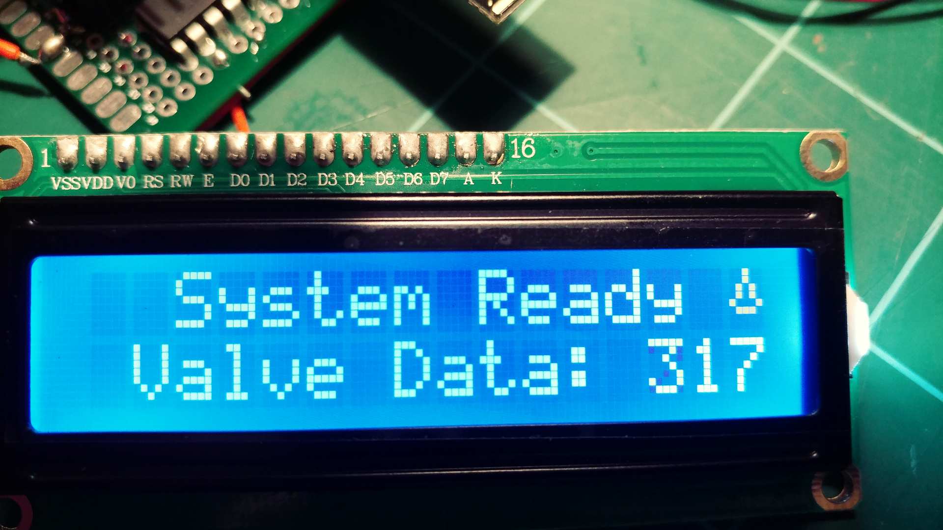
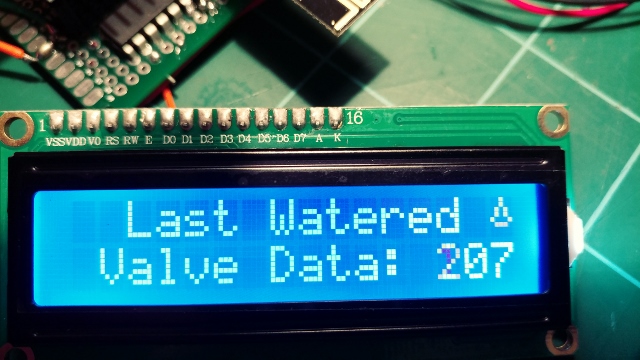
    great! it works.. happy++ The explanation: There is the variable named inSetup. Somewhere (outside any function) in the top of the sketch that variable is declared and at the same time initialized (given a value). bool inSetup = true; In the rest of the sketch, that variable's value is never changed: The value of inSetup is always the same, all the time. It's value simply remains the same. In every Arduino-sketch you're obligated to define two special functions, namely: setup() and loop(). If you don't have them in your sketch, the sketch would not compile. The setup() function is executed only once. It is called at the beginning of any Arduino sketch. It's used to do things that only need to be done one time, like setting pins to input or output, or perhaps even displaying a startup text on a connected display. The loop() function holds the code that is executed repeatedly. All of it's code is run, and when all that code is done executing (and the loop-code is finished), the Arduino just starts all that loop-code anew. Normally, it keeps on doing that until the power goes off. In your sketch's loop() function, there is a call to: goGetValveTimes();. Code in the loop() is executed over and over again. That means, that also goGetValveTimes() is executed over and over again. Now suppose your LCD is full of text, already been displayed in other parts of the code. Every loop() cycle will make a call to goGetValveTimes(). In that function named goGetValveTimes() is that block of code that is executed: if (inSetup) { lcd.print(F(" Updating ")); lcd.setCursor(0, 1); lcd.print(F(" Valve Data: ")); lcd.print(valveIndex); } Code inside that block is always executed. It sets the cursor, and prints the valve data line. It is always executed because the variable inSetup is always true. Therefore no matter what was on your LCD, in every loop() cycle, that line on the display is overwritten with the valve data.. just as it is instructed to do. Another way to fix the problem, while keeping that block of code (displaying the valve data), is to set the value of variable inSetup to false at the right moment. That way the code block is not executed anymore, and will no longer keep overwriting your text already on the display. Probably the best moment to do that, is at the end of the setup() function. like so: void setup() { // at the end of your setup() function it would then look like this: goGetValveTimes(); } lcd.clear(); inSetup = false; } I believe that explains what was going on in your sketch..

  • Watering flowers on the balcony + LED illumination

    3
    1 Votes
    3 Posts
    2k Views
    TmasterT
    Nice. i`m building an version that control just 2 selenoids valvs 24v AC controlled by 5-12v DC . i will post it when its ready.stills testing the humidity sensor .. i build it from scratch because i change all the smart features to the sensors instead of depending from the gw. one of selenoids work all days ,the other just day yes ,day not.
  • RF433 NODE, help with code

    4
    4
    1 Votes
    4 Posts
    2k Views
    S
    @craktor - after a power failuer you can request it by using v_var1 i think Check the pulse power meter example on how to :)
  • This topic is deleted!

    1
    0 Votes
    1 Posts
    6 Views
    No one has replied
  • Another simple (No SMT) relay actuator

    42
    5 Votes
    42 Posts
    15k Views
    breimannB
    @dpressle Nice job!
  • This topic is deleted!

    1
    0 Votes
    1 Posts
    13 Views
    No one has replied
  • LCD Display Incorrect

    1
    2
    0 Votes
    1 Posts
    946 Views
    No one has replied
  • 2 Votes
    3 Posts
    4k Views
    core_cC
    Thanks gohan.. This forum is a great source of inspiration. Lots of examples of people and their own projects, and/or problems they encounter(ed). I'm fairly new to MySensors & Arduino, but i have a lot of experience with Atmel AVR. At this time, i'm more reading than writing: absorbing info first. Hopefully i can help out others too sometimes.. it's cool to share knowledge. I already have 10 Arduino Yúns & 2 Raspberries at my disposal (they belong to friends i'm helping out). It would be fun to find a sensible application to combine a MySensors radio network (or perhaps multiple networks), and the IOT-capabilities of the Yún(s) & Raspberries. But that's another project..
  • Scrolling Text sensor node with new V_TEXT

    51
    7 Votes
    51 Posts
    34k Views
    S
    I just did send(msg2.set(reason.c_str())); and it worked. Thanks @AWI
  • Domoticz(Raspberry) with Mysensor USB gateway without Radio

    6
    0 Votes
    6 Posts
    4k Views
    D
    Ok, I find. Sketchinfo was in Presntation, and should be in setup. void setup() { // Send the sketch version information to the gateway and Controller sendSketchInfo("Salon_Parents_SdJ", "1.0"); for (int sensor=RELAY_Sejour_Volet1_Bas, pin=RELAY_Sejour_Volet1_Bas; sensor<=NUMBER_OF_RELAYS; sensor++, pin++) { // Register all sensors to gw (they will be created as child devices) present(sensor, S_BINARY); } for (int sensor=IN_Sejour_Presence1, pin=IN_Sejour_Presence1; sensor<=NUMBER_OF_INPUT; sensor++, pin++) { // Register all sensors to gw (they will be created as child devices) present(sensor, S_MOTION); } }```
  • Low Voltage Whole House Power Supply

    13
    9 Votes
    13 Posts
    10k Views
    JonnyDev13J
    @petewill Thanks for explaining. That will be helpful if I get to the point where I can try to do something like this!
  • Central Heating Controls

    4
    0 Votes
    4 Posts
    2k Views
    gohanG
    It depends if it is a normal relay on/off command or a bus communication. If it is the first case you could replace it with a node and a relay (could be arduino mini pro or esp8266 + relay) and a temperature sensor and set up the controller with time schedule and temperatures you want during the day. My personal suggestion if you have just an on/off command is to get something like a Netatmo thermostat (I have one and I am so happy with it) because they use a learning algorithm that adapts automatically according to your house heating system that keeps temperature constant taking advantage of the heating inertia (implementing it in a controller is really an hassle). For water heating it is simpler as you may just need a relay and schedule on/off on the controller

15

Online

12.0k

Users

11.2k

Topics

113.4k

Posts