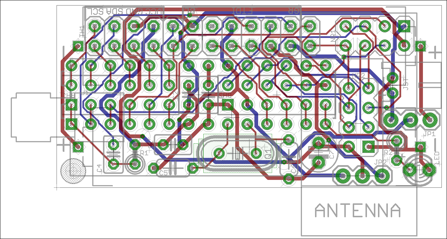
My own board (50mm x 30mm)
-
Hi all,
i was never happy with the arduino pro mini and i dont like smd (too small for me). I was inspired by another design and so i decided to create my own board with "normal" components. i am not sure if everything is right, because this is my first selfmade pcb-design an my first project with eagle. So, i hope you can take a look at it and tell me, if something is wrong or what i can improve.
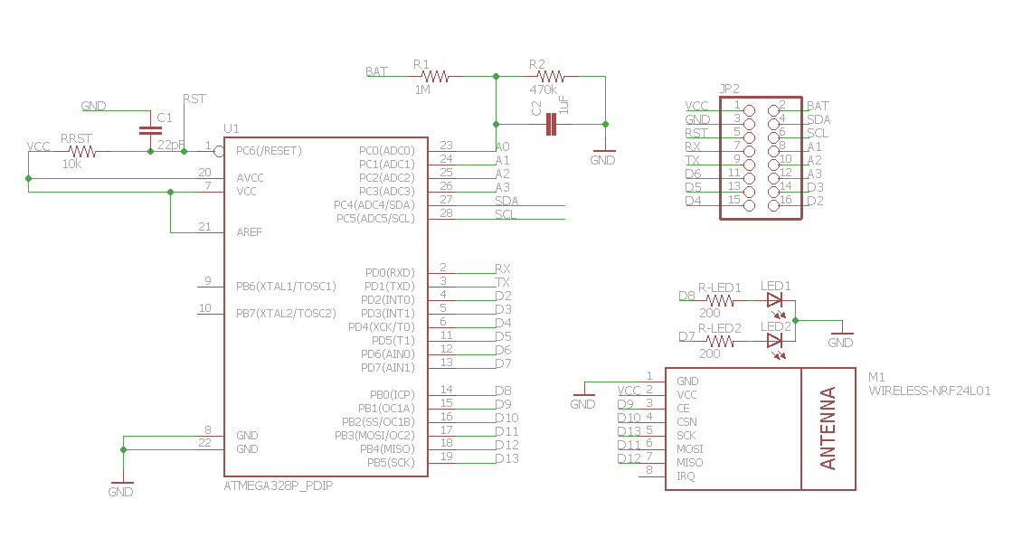
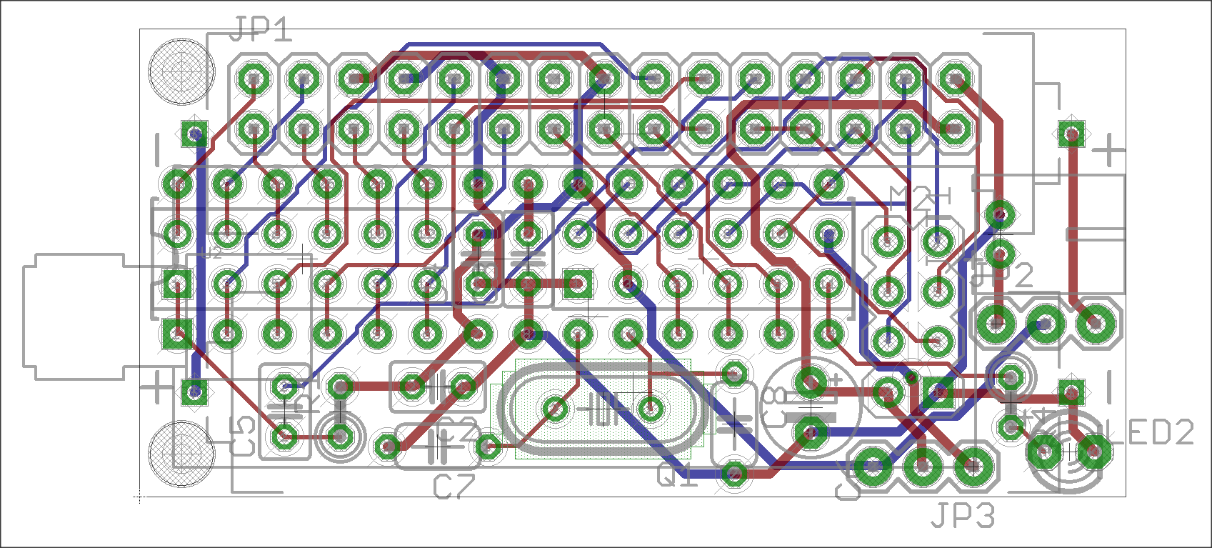
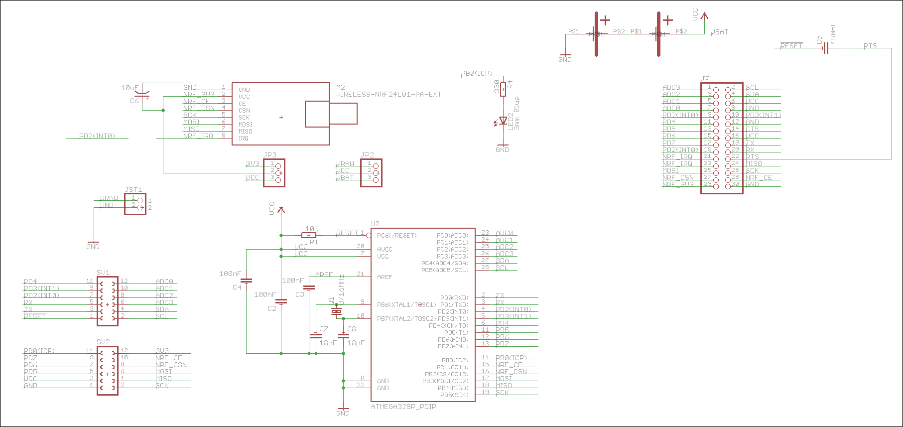
This is the design:
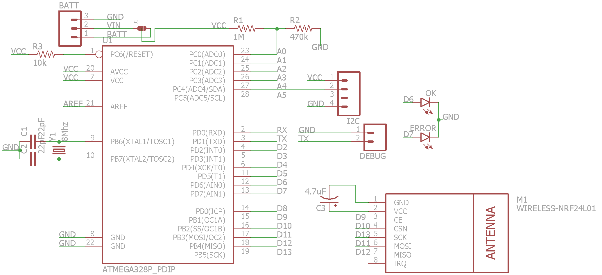
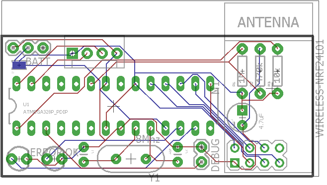
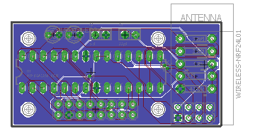
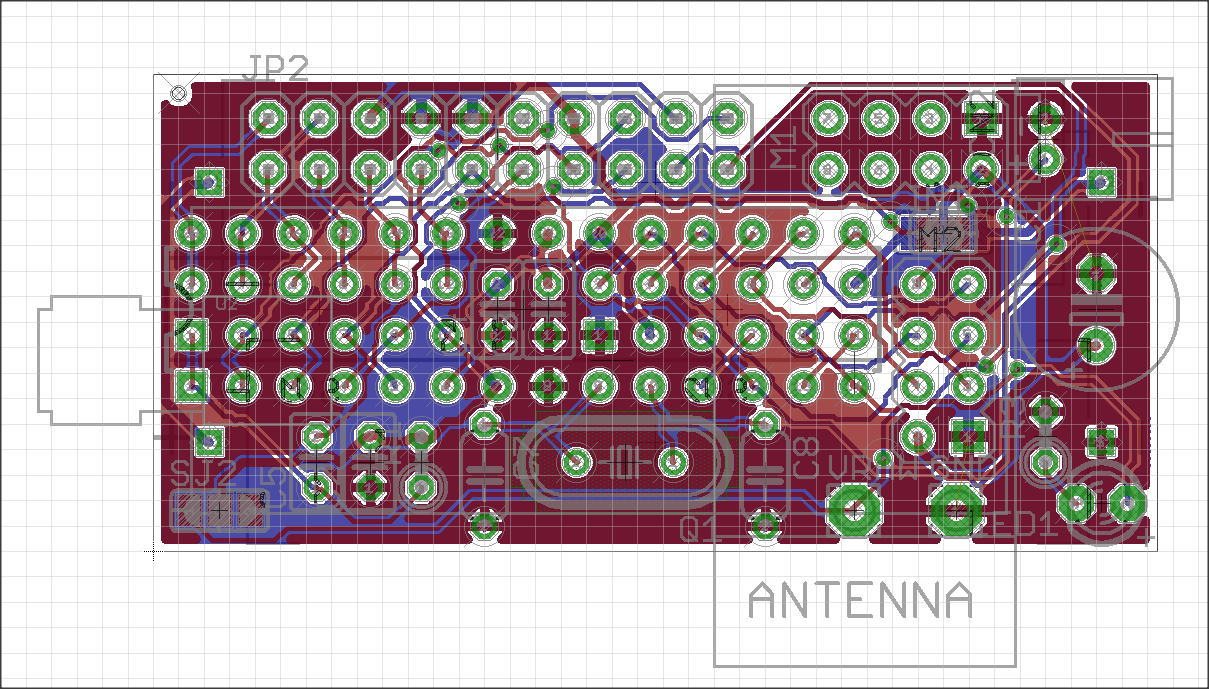
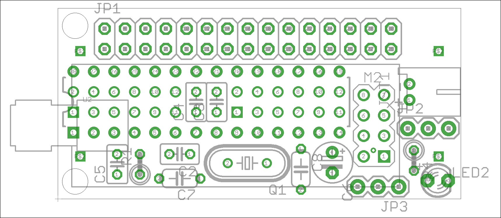
And this is the board.
Some background-info: I want to design an own board for every type of sensor i need. In detail:
- 4x DS18B20 - powered with 3.3v-boost converter( seperate pcb)
- I2C connector for LCD or Temp-Sensor (HTU21D)
- Analog-Inputs for Moisture-Sensors
- PIR-Board
Here is only I2C-board. The other boards are nearly "identical" except pinouts...
Every board has the same basic-features:
- 2 LEDS (OK & Error)
- Debug-Port (TX & GND)
- Pinouts at same pcb-side (top)
-Voltage Monitor included with solder jumper to chose input voltage. Reason: If the board is powered vi 3.3v booster, i need to monitor the raw-battery-voltage.
The board is designed with eagle and seeedstudio design-rule. So i will order them when i have finished the design....
What do you think about this?
Greetings
Andreas
-
Hi, it's great board, this is what i'm looking for!
The only thing is that you can add Ultra-small DC-DC 0.8-3.3V to DC 3.3V Step UP Boost not as separate module, but on the main board, for example:
http://www.aliexpress.com/item/Ultra-small-DC-DC-0-8-3-3V-to-DC-3-3V-Step-UP-Boost-PFM/32253709053.htmlWhat do You think?
Best regards -
Hi,
i thougt a long time about placing such a booster on the pcb. Its quite difficult to find a good(!) booster. Lots of the cheaper booster draw a lot of current (quiescent current) - like the one behind your link. I tested only 2 until today.
This one: http://www.exp-tech.de/pololu-3-3v-step-up-spannungsregler-u1v10f3?gclid=CPmll6rH0ccCFRI6Gwod884Lxg
and this one: http://www.exp-tech.de/sparkfun-ncp1402-3-3v-step-up-breakout-prt-10967?gclid=CPCv55_H0ccCFUu6GwodKDUHwACurrent consumption differs approx 30uA between those 2 (red 70uA, green 100uA in sleepmode with sensors etc)...
Did you check current-consumption of your booster?Actually i am changing the board size to 50mmx24mm - its a lot cheaper to order from fusionpcb (seeedstudio)...
Thats a lot.
Greetings[▲QUICK EDIT]
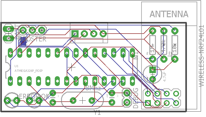
Something like this? Booster soldered vertical....In this way you must select with the solder jumper how to power the board (battery direct or via booster)...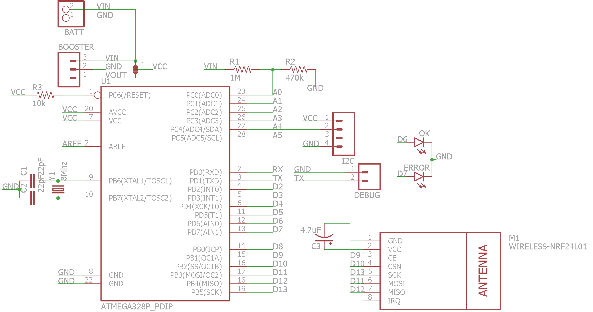
-
Looks nice. Some initial thoughts:
- Shouldn't IRQ in the radio be attached to the arduino?
- Is the capacitor under the radio on the opposite side of the board (clearance issues)?
- You might want to add mounting holes. They need more clearance than you might expect for screw sizes. See this link for details
- Is the capacitor C3 connected to the radios VCC pin? It looks like it might be connected to VCC but not to the actual pin on the radio. Bypass caps should be as wired as close to the component pins as possible.
Hope that helps. I'm working on my first board right now as well so keep in mind that those comments are from another amateur and could be totally wrong :smiley:
-
Hi,
thanks for your feedback guys :). Looks like i am on the right way. Only some things before breakfast (hope my wife doesnt see me at the notebook instead of making breakfast) ;) I will answer the other tipps and questions later from work ;)
- IRQ-PIN: Is not needed for batterypowered devices, because the radio cannot wake up the IC.
- Cap C3: Plan was to solder it horicontal - i just didnt find the part in eagle. Both, atmega and nrf, will be mounted into sockets. So there should be enough space under the NRF module for a 4mm Cap. But maybe your are right and its easier to solder the cap directly onto every NRF-module...
- Case: I have no 3D-Printer, only CNC. So i have an Idea for a case - incl. Batteryholder. But i will show this later. Its only in my mind, not in my CAD-Programm actually ;)
- Mounting holes: is a "ToDo" ;)
Greetings
Andreas -
-
This post is deleted!
-
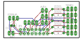
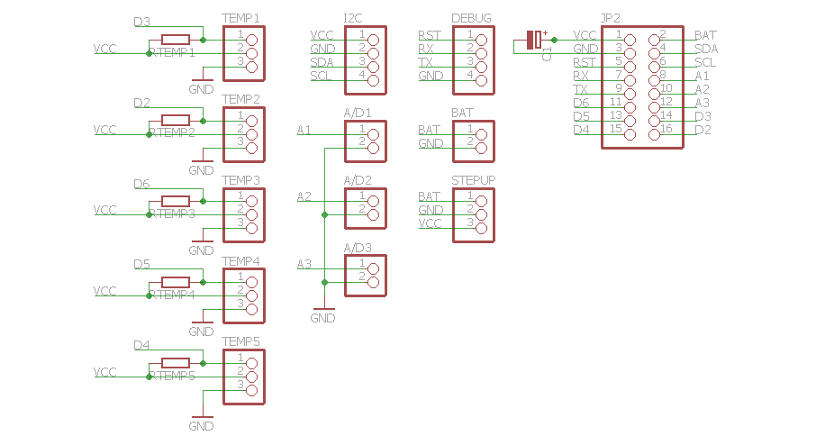
My development continued. I have now a "Baseboard" and a "Topboard". First i created different topboards for different sensors. But at last i made a "general" Topboard. Here i can connect all the sensors i need. It has
- 5x Digital-Connectors prepared for DS18B20 (GND, SIG & VCC), but can be used for other digital in-outputs. Just do not solder the resistor
- 3x Analog-Connectors for connecting analog-devices. (can also be used as digital pins)
- Place for an Step-Up-Module. If the sensor is powered directly with 2xAA-battery just put a jumper to connect BAT & VCC.
- I2C -Connector with VCC and GND
- Batterymonitor-Pin for Baseboard (A0)
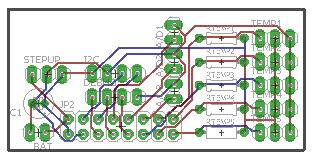
This is the Topboard:
 !
!
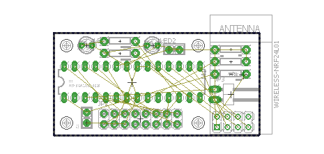
The Baseboard has:
- NO smd-parts
- Debug-port (TX &GND)
- Mysensor-Voltage-Monitor (2 resistors) onboard. Solder it or not if not needed
- 2x LEDs (Red & green) = Error & OK
- 4x 3.2mm holes for mounting
This is the Baseboard:
 !
!
Both boards are 25x50mm...
Now i have to find out how to print them in 1:1 (original size) for testing. -
Here is some feedback from designing my boards:
You need 100nF capacitors between AVCC and GND and between VCC and GND.Put them as close to the actual pins as possible. And you need to pull ARef to ground via a capacitor (can be 100nF as well). All this improves stability of powersupply to the processor (and less restarts)
To test the battery voltage (if powered directly from 2 AA or 2AAA batteries, there is no need to use the 2 resistors, there is a routine to test the battery voltage based on internal reference (so no analog input pin needed).
You could use a single LED to show what is going on: slow blink means all OK, fast repeated blink means error. This saves a resistor/led/output pin.
The 100uF capacitor is a 8x12mm type and fits just under the NRF24. You can go for a 10uF which are normally a bit smaller and have no clearance issues (only 8mm high, so well below the 12mm space available).
How do you plan to program the board ? It could be nice to add the FTDI comptible header on the top board, or you can also add it on the main board.
Here is a link to my design:
https://oshpark.com/shared_projects/qnkNIMZxSchematic is in the next post.
Like yourself I only use through-hole components (except on the extention board). I can add extentions on top or on the bottom of my board.
Another tip I got from other people: powerlines need wider traces,
I have been thinking about replacing one of the headers I added (for the top boards) with a header according to the MYSX 1.5 specification. So far I have not finished this, but it is on the todo list.
A 50mm by 24mm board allows powering by two AAA batteries onboard, so my next design provides for this as well (it's a work in progress).
But after three designs I now work in reverse: first look for a nice suitable case, then design the board to fit with ITEAD/DirtyPCB spec (50mm x 24mm to have 2 boards out of a 50x50mm run).
Since I test on prototype boards and transfer sketches to "final" boards later, I think I can integrate the FTDI header into JP1. I also plan to re-arrange the I2C pins so that I can plug in boards from Sparkfun, without any adapter. They (Sparkfun) use a fixed sequence for all their I2C boards:
GND - VCC - SDA - SCL
Some boards are VCC - GND - SCL - SDA. Not sure which is more popular, as I have seen both on Aliexpress and eBay. -
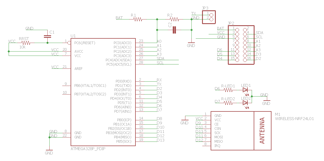
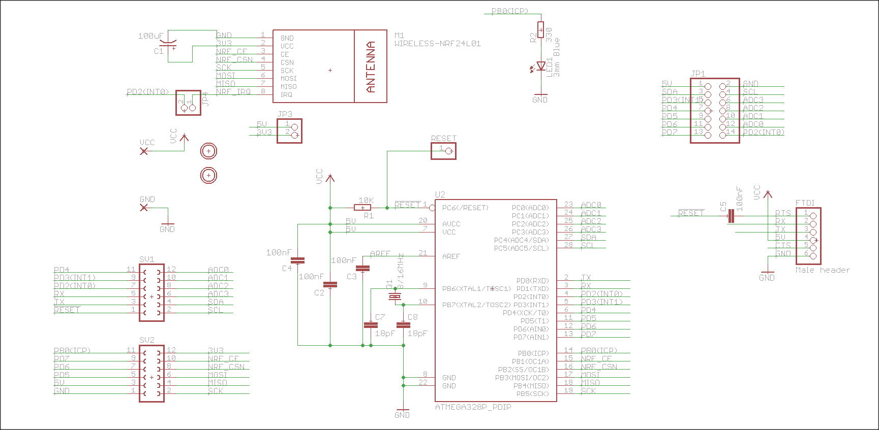
Here is the schematic of my current v1-1 board (based on the work of many other people):
The new (battery included) board is still to "fluid" to show. When fixed I will probably also share this on OSHPark.
-
Hi Gert,
thx for your feedback. Lets make a small structure to discuss the things:
Battery-monitoring
I plan to you use the AREF as 3.3v Reference powered by the step-up-module. I think most of my sensors will have a step up. So this should be quite easy and accurate. In this case i solder a wire instead of R1 and "unsolder" R2....
OR (if i really want) i can use the voltage divider on A0 instead (like mysensors.org says). I think with this schematics i have both possibilities... How does it work without resistors and internal vref (1.1v)? I only saw the version with 2 resistors on the mysensors page.
By the way: I tested 3 step-up-modules:Pololu with NCP1402
Sparkfun with NCP1402
"China-Module"The China-Module is crap (+-240uA).
Pololu draws +-100uA in sleep mode
The Sparkfunboard only draws +-30uA in Sleep mode. I will go for that.Capacitors:
There is a capacitor between VCC and GND. The capa between AVCC and GND is missing, you're right. Thx.
I want to use AREF, so i cannot pull it to ground. Or what did you mean? Or am i missunderstanding something? I thougt AVCC is the supply voltage for the "REF"-function. And AREF is the reference-voltage....Programming
In an updated version from last night, i moved the debugport to the topboard. I can upload new sketches via RX/TX...
Do you know if it is possible to use the ISP when the NRF24l01+ is still connected to these pins?LED
I dont want to have a regular LED-blink (power consumption). It shall only blink when working(transmitting).
Green => All OK: Measures are ok, packet was sent
RED => ERROR: Measurement fails or packet could not be sent...
A DUOled would save some space, but no pins.Sensors
I think i will have a max of 5 Sensors connected on one board , so there is no need to save pins whereever i can.
The I2C port is like the sparkfun "standard" ;) I have a lot of HTU21D-BOBs laying around. They work like a charmAfter i gave my child something to eat, i update and upload the schematics...give me some time ;)
-
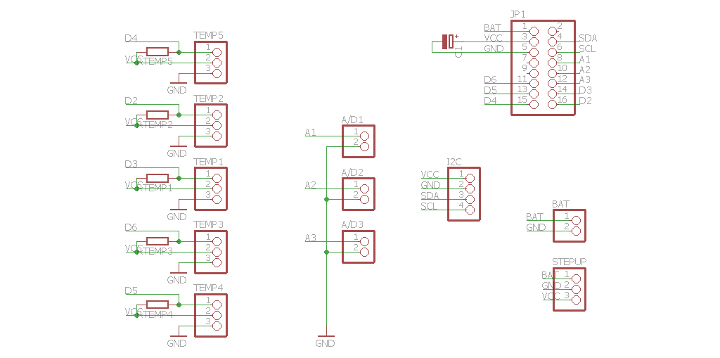
Here the schematics with boards..
Baseboard
Topboard
-
Battery-monitoring
The capacitor between AREF and ground (C3 in my schematic) is not to pull that pin to ground, but to stabilise this reference. Not strickly needed I think, but I prefer it since my sensors will live in a "noisy" environment.The code to check the level of VCC using the internal 1.1V reference is found here:
http://provideyourown.com/2012/secret-arduino-voltmeter-measure-battery-voltage/The error of 10% is something I can live with, since I need to be able to measure the supply-voltage and monitor it. It does not need to be super exact, since I plan to replace the batteries when I see levels around 2.2V. I'm mostly interested in the trend graph.
When using a DC stepup converter, you will of course need to use a pin to measure the original battery level, because the step up will make VCC always 3V3. I like your idea of dual use, so I will implement the pins to hold a voltage divider anyway. It is indeed a good use of PCB space.
I also ordered some step up converters (from Aliexpress) and I will measure them once I get them. Not all China stepups are crap it seems (as far as I read on various websites).
LED
As for the LEDs, I have only 1 LED on my boards. The LED blinks very shortly (5ms) every minute to show that a message is sent. It flashes three times if there is an error. So no need to have two leds. It is also the same LED that is flashed by the bootrom (I'm compiled nmy own version of Optiboot to used pin 14 of the atmega328. On a atmega1284p I use pin 1. This is personal preference.I checked your schematic. You will need to change the value of C1 (it is now 22pF, will need to be 100nF).
I will need to read the datasheet of the atmega328 again to understand the exact use of AREF. I'm not sure that pulling this to VCC is a good idea.
It seems you have removed the crystal and capacitors and plan to use the internal oscillator, I did this as well. Works most of the time, but uploading of sketches can give transmission errors of you go above 57K6 baud. Better to transmit at 36Kbit then (needs a change in the BOARDS.TXT file of Arduino IDE). Slower, but not a problem if you do not plan to change the sketch every 5 minutes.
Here is a preview of my new board:
It will be able to work both as a repeater (NRF24 with antenna) as well as a normal sensor board (small NRF24). The voltage divider on A0 is not yet implemented here. Still some empty spaces :-)
-
Hi,
thx for the feedback. Capa is changed to 100nF. It also works on my breadboard with 22pF ;)
Battery-Monitoring
The link to measure the vcc internally is great! Wow! Does this solution block any pins?
But i stay with my double-solution - it is not too big on the pcb.Crystal
Yes, i progged the fuses to run at 8Mhz-internal. Runs great and saves parts on the pcb and makes it cheaper ;)i am not sure, i understand your board. What are all the connectors for? Where is the ATMEGA? Size?
Maybe we can join our board-ideas and design one-board together? ;)
I am missing mounting holes on your pcb...
Case
I willl make my own case - a wooden case milled with my CNC...
8mm Multiplex (or plywood)...looks quite good i think ;) -
Different version with mounting holes:
Schematic:
Topsilk+documentationlayer:
Bottomsilk +documentationlayer:
As I said: a work in progress. Nothing fixed yet.
-
Incredible many pinouts and holes! Wow! Are you sure you need them all? Looks much more complicated then my design. But looks cool, too :)
This is my Case-Prototype - very flexible and easy to manufacture:
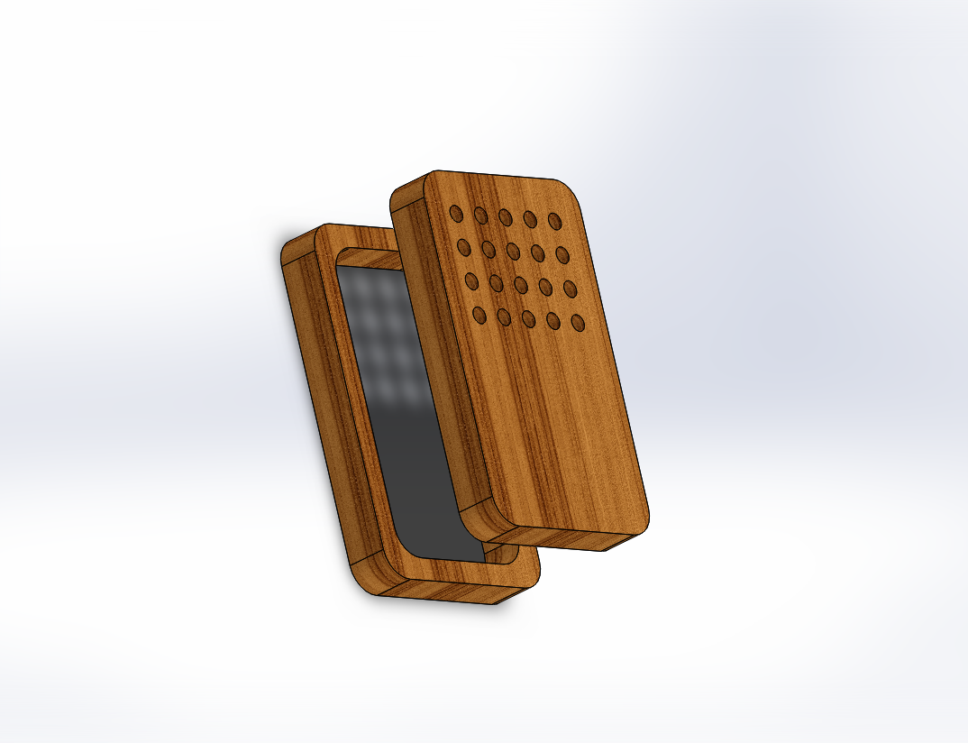
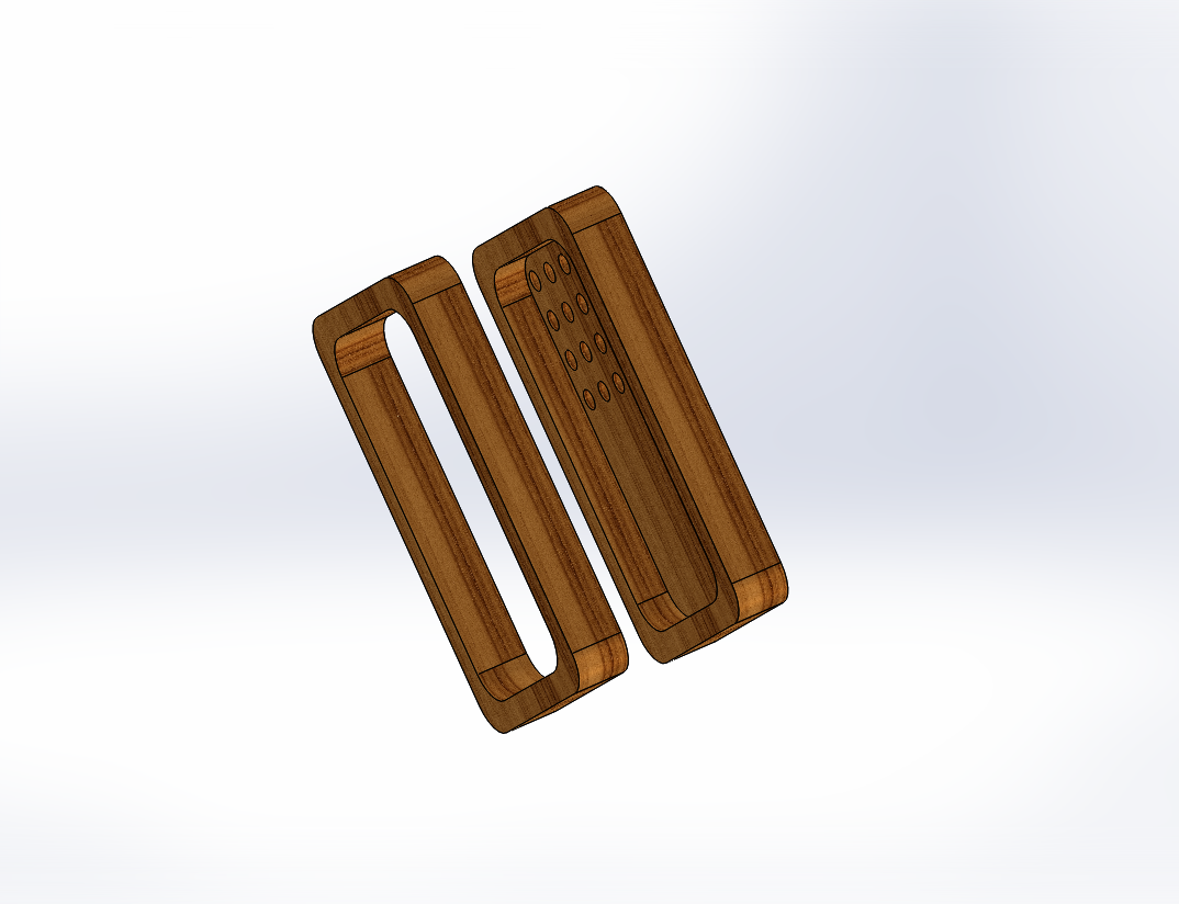
The top is adapted to every node-type. E.g. in the picture is the top for the humidity and temperature sensor. Then i plan to create a top for a PIR-Sensor, Acoustic-Sensor and a case for external Sensors and Powersupply, too.
Maybe i engrave the type of the sensor into the top for a cool looking.Then i glue it together or use small magnets. Case is still in "alpha"-status - work in progress. If i need it higher, i just add a second, third (...) bottom part. Every part is made of 8mm wood. If i want another design, i can make a "cover" for the top or use other materials for this (Aluminium, POM,different wood, acryl...) Connections from the side are easy to realise, too. Just drill a hole after building or mill it before putting it together.
If i could make a 3D-Modell from my PCB (and know how to do this with eagle), i could make a really nice picture with case, pcb and batteries...Size is approx 60x40mm.
Greetings
Andreas
-
Incredible many pinouts and holes! Wow! Are you sure you need them all? Looks much more complicated then my design. But looks cool, too :)
This is my Case-Prototype - very flexible and easy to manufacture:
The top is adapted to every node-type. E.g. in the picture is the top for the humidity and temperature sensor. Then i plan to create a top for a PIR-Sensor, Acoustic-Sensor and a case for external Sensors and Powersupply, too.
Maybe i engrave the type of the sensor into the top for a cool looking.Then i glue it together or use small magnets. Case is still in "alpha"-status - work in progress. If i need it higher, i just add a second, third (...) bottom part. Every part is made of 8mm wood. If i want another design, i can make a "cover" for the top or use other materials for this (Aluminium, POM,different wood, acryl...) Connections from the side are easy to realise, too. Just drill a hole after building or mill it before putting it together.
If i could make a 3D-Modell from my PCB (and know how to do this with eagle), i could make a really nice picture with case, pcb and batteries...Size is approx 60x40mm.
Greetings
Andreas
-
@Andreas: nice woodcase. Do you have access to a CNC machine at home or at work ?
My design is based on the idea that I want to have a maximum of options with the same PCB. Last night I printed some boardoutlines on paper and then placed the actual components on top. I find limitations in space this way. My idea of 1 long connector has a disadvantage: the small radio covers 4 pins, so that a top board would not be able to plug into these. I went back to a seperate header for the small radio and for the top board.
Still thinking about powering options. VRAW (anything external), VCC (regulated to maximum 5V, e.g. from a USB port), 3V3 (regulated via bottom- or top-daughter boards), VBAT (from onboard AAA batteries). The problem is finding an elegant and easy way to choose. Solderpads are compact, but permanent. Jumpers are easy but big. Small toggle- or slide-switches are expensive.The fruit of last night's meditations:
I have still not decided if I should use the pintout of the SI7021 breakout modules (VCC-GND-SCL-SDA) or the HTU21D (VCC-GND-SDA-SCL). Most breakouts seems to use 3V3, so I may need to plan for that.
Hello! It looks like you're interested in this conversation, but you don't have an account yet.
Getting fed up of having to scroll through the same posts each visit? When you register for an account, you'll always come back to exactly where you were before, and choose to be notified of new replies (either via email, or push notification). You'll also be able to save bookmarks and upvote posts to show your appreciation to other community members.
With your input, this post could be even better 💗
Register Login