Capacitors and switching power supplies
-
I am using external chargers 5V for powering my sensors (some are old branded nokia ones, others are a cheap chinese replacement).
Power goes to arduino VCC (arduino pro mini 5V) and also the NRF24 adapter board (containing the voltage regulator and some capacitors - got it off aliexpress).I wonder if adding a decoupling capacitor just before power is split to arduino and NRF24 board will help in any way. If yes what is the best value for the capacitor?
-
I was wondering on the best practices
-
@moskovskiy82 said:
I am using external chargers 5V for powering my sensors (some are old branded nokia ones, others are a cheap chinese replacement).
Power goes to arduino VCC (arduino pro mini 5V) and also the NRF24 adapter board (containing the voltage regulator and some capacitors - got it off aliexpress).I wonder if adding a decoupling capacitor just before power is split to arduino and NRF24 board will help in any way. If yes what is the best value for the capacitor?
Well, the arduino should have some decoupling on the board itself, also the decoupling on the NRF24 adapter board should be sufficent.
You could add a low-pass filter after the power supply (are your supplys switching regulators?) to reduce the ripple produced, but the frequency rejection of the linear regulators should also handle this fine. -
@moskovskiy82 said:
I am using external chargers 5V for powering my sensors (some are old branded nokia ones, others are a cheap chinese replacement).
Power goes to arduino VCC (arduino pro mini 5V) and also the NRF24 adapter board (containing the voltage regulator and some capacitors - got it off aliexpress).I wonder if adding a decoupling capacitor just before power is split to arduino and NRF24 board will help in any way. If yes what is the best value for the capacitor?
Well, the arduino should have some decoupling on the board itself, also the decoupling on the NRF24 adapter board should be sufficent.
You could add a low-pass filter after the power supply (are your supplys switching regulators?) to reduce the ripple produced, but the frequency rejection of the linear regulators should also handle this fine.Thanks for the great explanation!
-
@moskovskiy82 said:
I am using external chargers 5V for powering my sensors (some are old branded nokia ones, others are a cheap chinese replacement).
Power goes to arduino VCC (arduino pro mini 5V) and also the NRF24 adapter board (containing the voltage regulator and some capacitors - got it off aliexpress).I wonder if adding a decoupling capacitor just before power is split to arduino and NRF24 board will help in any way. If yes what is the best value for the capacitor?
Well, the arduino should have some decoupling on the board itself, also the decoupling on the NRF24 adapter board should be sufficent.
You could add a low-pass filter after the power supply (are your supplys switching regulators?) to reduce the ripple produced, but the frequency rejection of the linear regulators should also handle this fine.@Oitzu do you have a recipe for making such low-pass filter?
-
@Oitzu do you have a recipe for making such low-pass filter?
@ronnyandre Things are sooo easy (if you have a degree in electronics ;-) ) An effective design includes multiple filters and depends for a great deal on the switching frequency (and harmonics). A typical design could look like this.
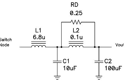
An linear regulator (like LM7805) can be very effective for low frequencies (~ < 10kHz) but not for high frequencies.
In most of the cases when working with phone mains adapters the 'standard' (uno/ nano) regulator (1117) with capacitors damps sufficiently.
-
Wow @AWI that looked more advanced than I thought.. :sweat_smile:
-
@ronnyandre The main reason for using a filter would be a crappy/cheap switching power supply.
I needed to use one of these filters on a cheap LM2596s (clone) module to filter the output to a nrf24l01+ pa/lna module.Unlike @AWI 's solution i just added a second stage after the first stage (that is on the module).
http://blog.blackoise.de/wp-content/uploads/2016/03/lc-filter-schem1.jpg
L1: 3.3µH
C1: 220µF
Worked fine enough to get the nrf24l01+ pa/lna module working. -
@ronnyandre The main reason for using a filter would be a crappy/cheap switching power supply.
I needed to use one of these filters on a cheap LM2596s (clone) module to filter the output to a nrf24l01+ pa/lna module.Unlike @AWI 's solution i just added a second stage after the first stage (that is on the module).
http://blog.blackoise.de/wp-content/uploads/2016/03/lc-filter-schem1.jpg
L1: 3.3µH
C1: 220µF
Worked fine enough to get the nrf24l01+ pa/lna module working.@Oitzu Thanks! I'll try that one out :simple_smile:
-
@ronnyandre The main reason for using a filter would be a crappy/cheap switching power supply.
I needed to use one of these filters on a cheap LM2596s (clone) module to filter the output to a nrf24l01+ pa/lna module.Unlike @AWI 's solution i just added a second stage after the first stage (that is on the module).
http://blog.blackoise.de/wp-content/uploads/2016/03/lc-filter-schem1.jpg
L1: 3.3µH
C1: 220µF
Worked fine enough to get the nrf24l01+ pa/lna module working. -
Hello! It looks like you're interested in this conversation, but you don't have an account yet.
Getting fed up of having to scroll through the same posts each visit? When you register for an account, you'll always come back to exactly where you were before, and choose to be notified of new replies (either via email, or push notification). You'll also be able to save bookmarks and upvote posts to show your appreciation to other community members.
With your input, this post could be even better 💗
Register Login