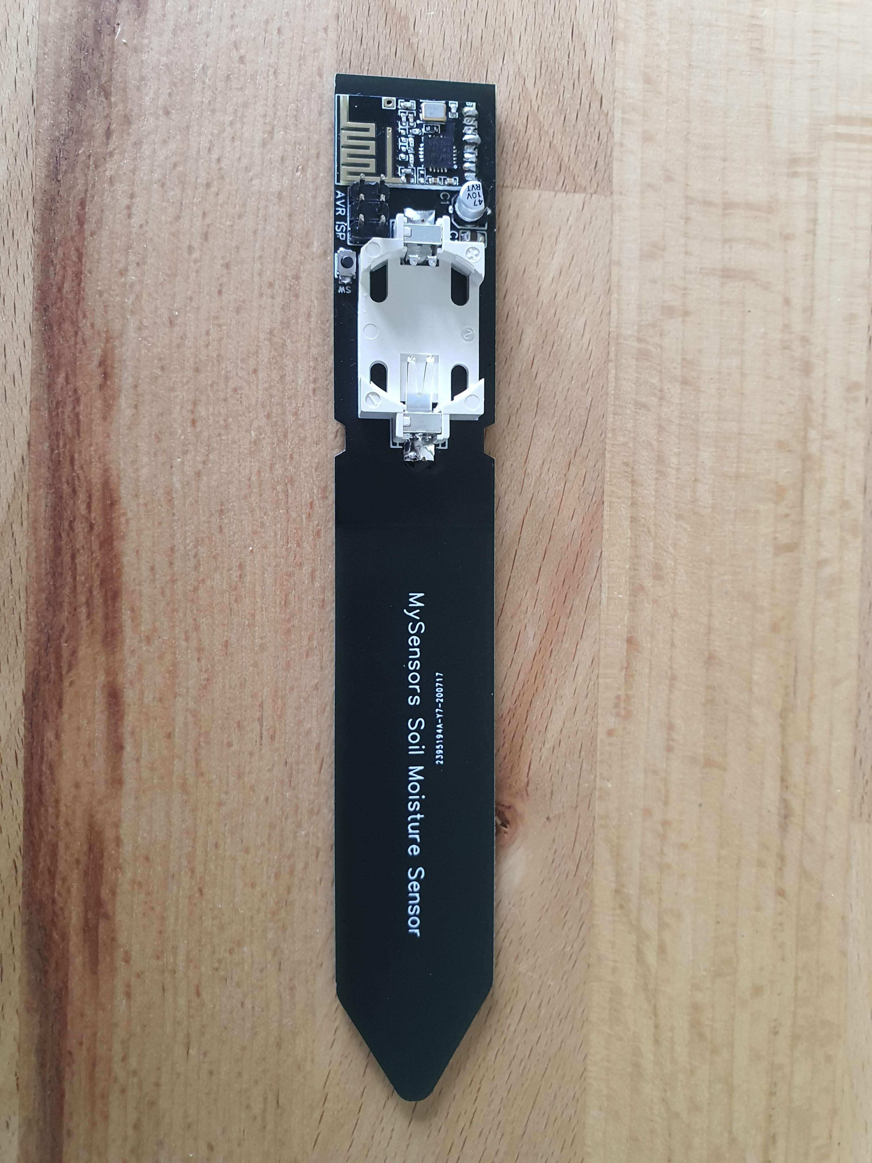
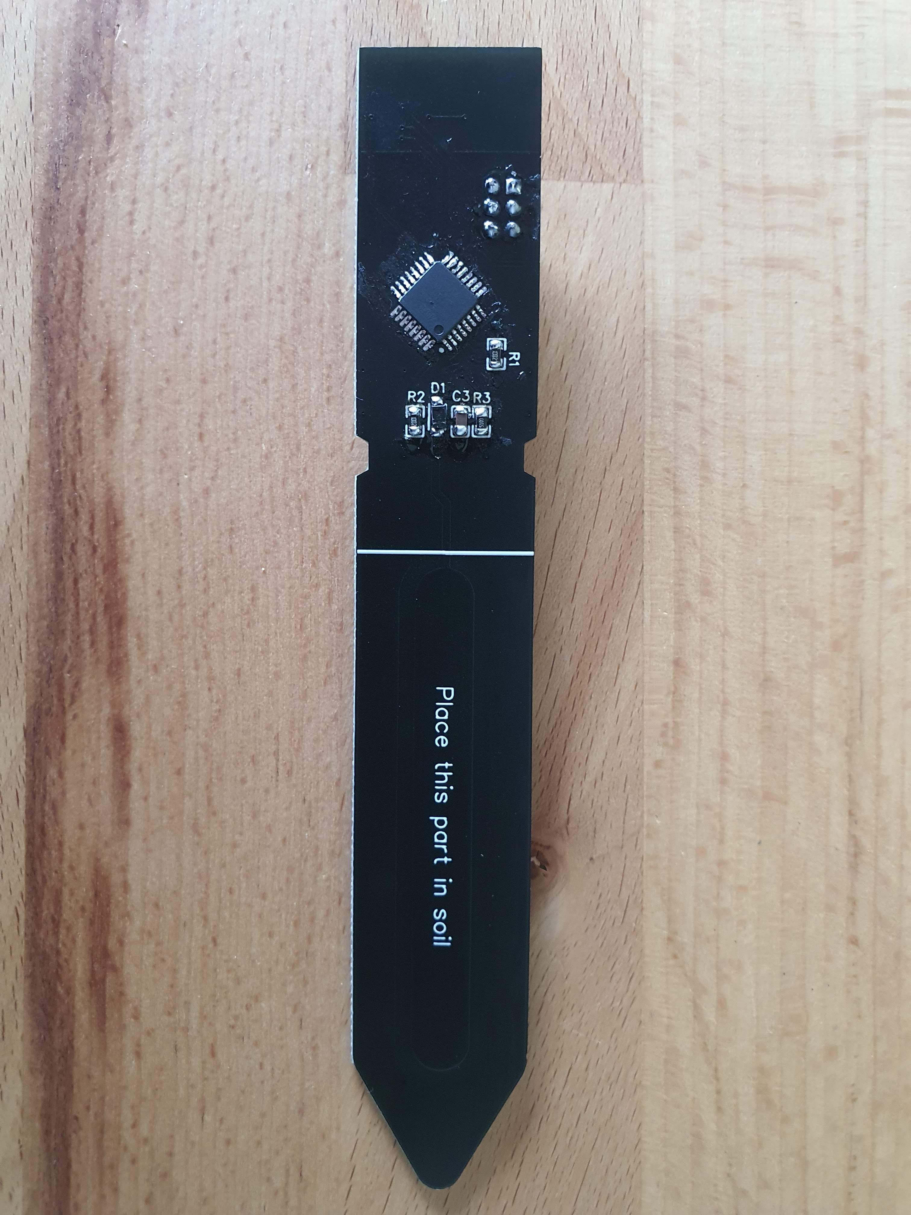
ATMEGA328P standalone soil moisture sensor
-
Hi everyone,
first of all thank you very much for this awesome project / community.
I recently got more and more interested in building sensors. My next project would be to add some capacitive soil moisture sensors to some plants around the house.
I know there are already a few sensors of this kind out there like these:
https://www.openhardware.io/view/767/Wireless-Module-for-Capacitive-Soil-Moisture-Sensor-v20#tabs-design
https://www.openhardware.io/view/672/Soil-moisture-meter#tabs-instructionsThe second one however, despite it is exactly what I was looking for, does not provide any design files.
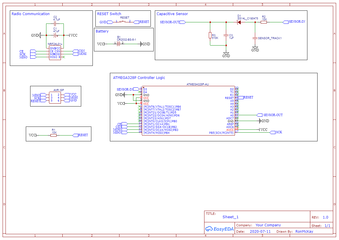
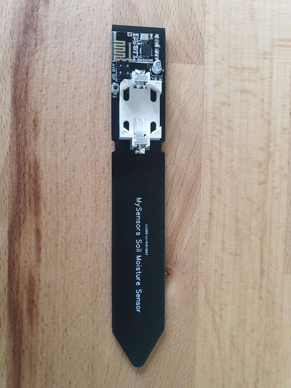
But as I wanted to learn more about electronics in general and also wanted to build my first smd pcb, I build my own capacitive soil moisture sensor based on an ATMEGA328P, NRF24L01+ and a 3V coin cell. The schematic is based on the chirp sensor and I oriented myself with regards to component selection at this project.
The good news is: It works!
But I already noticed some flaws (e.g. I forgot to add a FTDI connector besides the AVR ISP :man-facepalming: :laughing: ) and I could need some help from you:The voltage range that comes out of the sensor circuit is very limited. In air the analog pin reads about 570 while reading around 498 submerged in a glas of water.
I read this post and made my own calculations (I measured my probe to have between 20pF and 460pF). Based on these the voltage swing should be around 2.4V from minimum to maximum capacity. Now the real world is probably not exactly like the calculations but this difference seems a little bit large to me. Anything that I am missing here?
As additional information: I generate a 1 MHz square wave using the internal clock of the atmega by enabling fast pwm using the following bits:TCCR2A = (1 << COM2B1) // Clear OC2B on compare match | (1 << WGM21) // pwm mode 7 | (1 << WGM20); // pwm mode 7 TCCR2B = (1 << WGM22) // pwm mode 7 | (1 << CS20); // no prescaling OCR2A = 7; OCR2B = 3;In the setup function I set pin 3 (connected to OC2B) as output and pin 14 (A0) as input (this is where the sensor output goes in).
Any help on this would be greatly appreciated.
As soon as I finish the sensor (when I am no more bothered by the remaining flaws :grin: ) I will make it accessible for everyone.Thank you in advance for any advice or guidance.
Best regards,
Ron
-
I have a strong feeling that I got the wrong diode for the rectification of the triangular wave that comes out after the capacitive sensor (RC circuit). I got this one:
https://lcsc.com/product-detail/Schottky-Barrier-Diodes-SBD_Guangdong-Hottech-SS14L_C190475.html
In the datasheet it says that this diode has a Typical Junction Capacitance of between 90 and 110 pF which seems pretty high compared to the capacitance of the sensor. Do I need a diode with a lower capacitance?
Can someone give me a hint if I am on the right track?
Thank you :)Edit: Okey I switched the smd diode with an all purpose tht diode that I had lying around and now the voltage swing is already at 1.1V so it definitely is the diode. Any recommendations on diode selection for high frequency (1-4MHz) applications?
-
Hi everyone,
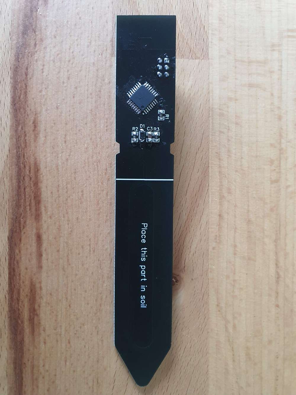
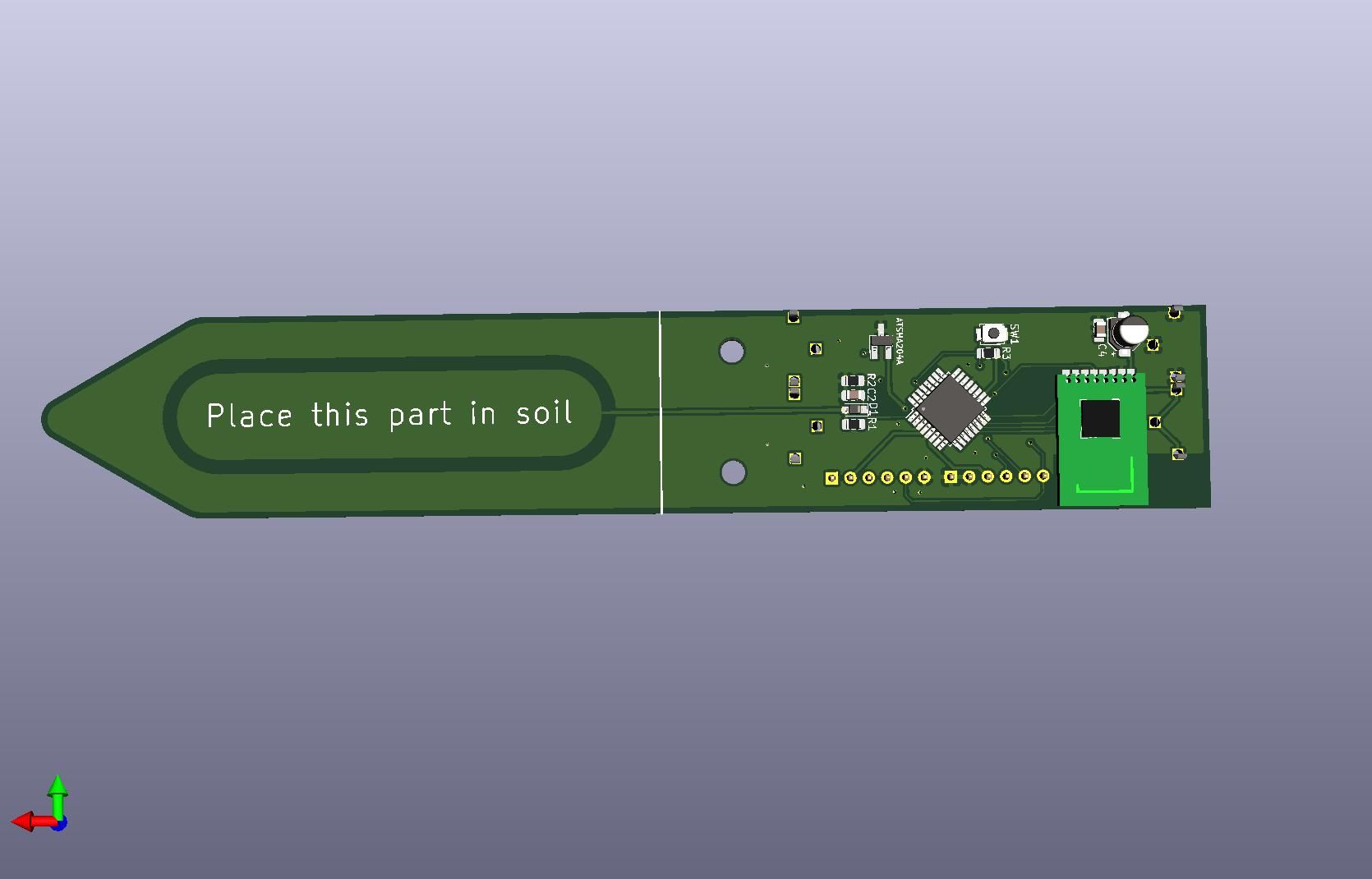
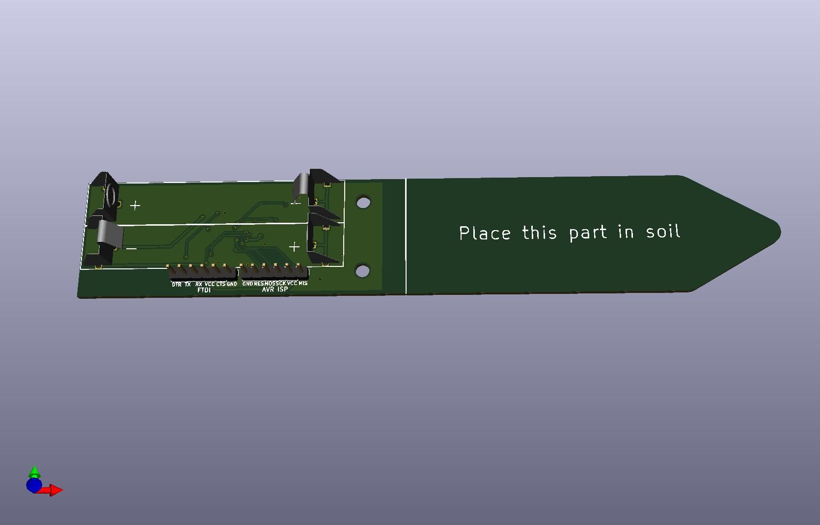
I have rebuild the sensor and this is the current status:
- Changed out the coincell for two AAA batteries due to higher capacity and better availability. This increased the sensor size in both height and width but this does not bother me.
- Added the possibility to attach an ATSHA204A in a SOT-23-3 package for message signing.
- Added an FTDI connection besides the AVR-ISP
- Changed from indentation to mounting holes. This makes it easier to design 3D printed cases for it.
Any nice features that I am missing here or that some of you would like to see on this? I am open for suggestions :)
PS: Is there any way to scale the uploaded images?
-
Hi there,
I am currently thinking about a power supply solution for the sensor. The possible options with their advantages/disadvantages are:
- Single AAA Battery Cell + dc-dc boost converter
+ compact formfactor
- not that much capacity
- additional costs because of boost converter hardware - Double AAA Battery
+ relatively large capacity and thus longer lifetime
+ no need of a booster which could introduce noise to the radio
- bulky (as you can see on the photos of my last post)
What bothers me is that without a booster I can only use two AAA batteries until they reach 2.7V in total, as I need at least 2.7V if I want to use the 8 MHz internal clock of the atmega.
Does it make sense to combine two AAA batteries with a boost converter to 3.3V? This way one could use the batteries until they reach ~2V in total.
I am interested to hear your thoughts on that. - Single AAA Battery Cell + dc-dc boost converter
-
@mfalkvidd said in ATMEGA328P standalone soil moisture sensor:
@Ron You can use 8MHz safely down to 2.34V according to the graph in the datasheet.
Are you sure with that? I found this information in the datasheet to the atmega328p-au, where it states that the safe operating range ends at 2.7V:
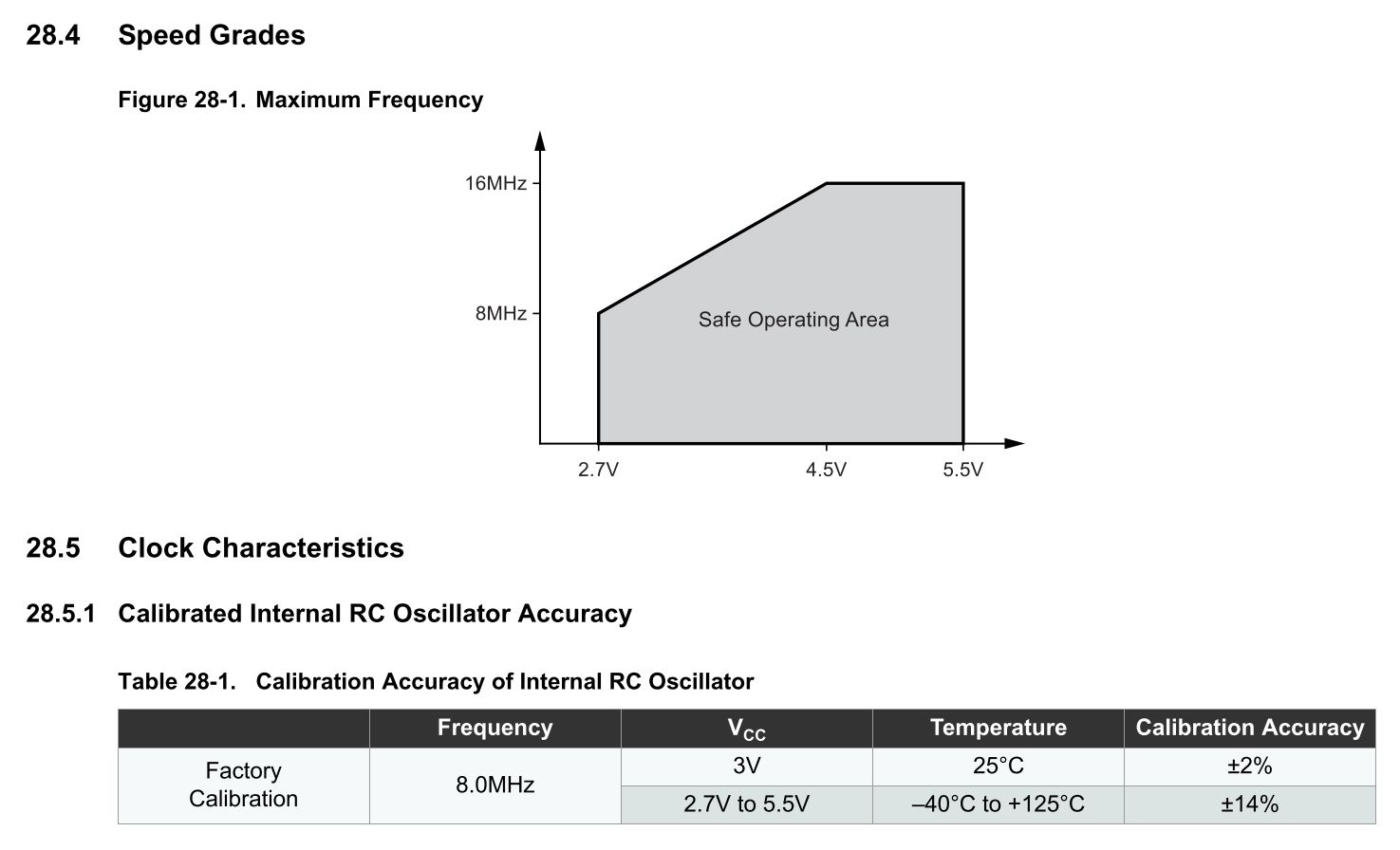
Maybe I should consider using an external oscillator instead of the internal one? Do you know something about the power consumption with an external crystal compared to the internal oscillator?
@mfalkvidd said in ATMEGA328P standalone soil moisture sensor:
For size, CR123a might be an option. They are lithium 3V, so one would be sufficient.
These ones look definitely interesting, I will have a look at them, thank you :)
-
@mfalkvidd said in ATMEGA328P standalone soil moisture sensor:
@Ron You can use 8MHz safely down to 2.34V according to the graph in the datasheet.
Are you sure with that? I found this information in the datasheet to the atmega328p-au, where it states that the safe operating range ends at 2.7V:

Maybe I should consider using an external oscillator instead of the internal one? Do you know something about the power consumption with an external crystal compared to the internal oscillator?
@mfalkvidd said in ATMEGA328P standalone soil moisture sensor:
For size, CR123a might be an option. They are lithium 3V, so one would be sufficient.
These ones look definitely interesting, I will have a look at them, thank you :)
-
@Ron interesting. This is what the graph looks like in my copy:
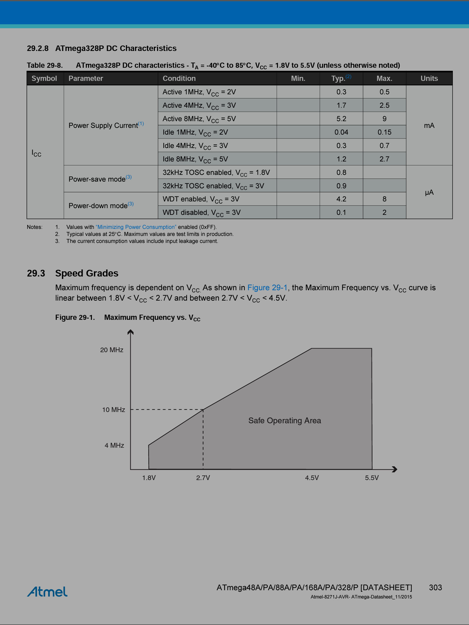
I guess the difference is P vs P-AU, and my datasheet might be an older revision.
@mfalkvidd you are right, I might somehow have found an older datasheet somewhere (my one was from 2015). In the current datasheet from the microchip website the same graph is present which indicates 2.4V minimum for 8 MHz. So I probably will deactivate 2.7V BOD. :)
-
@Ron interesting. This is what the graph looks like in my copy:

I guess the difference is P vs P-AU, and my datasheet might be an older revision.
@mfalkvidd said in ATMEGA328P standalone soil moisture sensor:
difference is P vs P-AU
You found the automotive grade datasheet, which contains a different curve
-
@mfalkvidd said in ATMEGA328P standalone soil moisture sensor:
difference is P vs P-AU
You found the automotive grade datasheet, which contains a different curve

