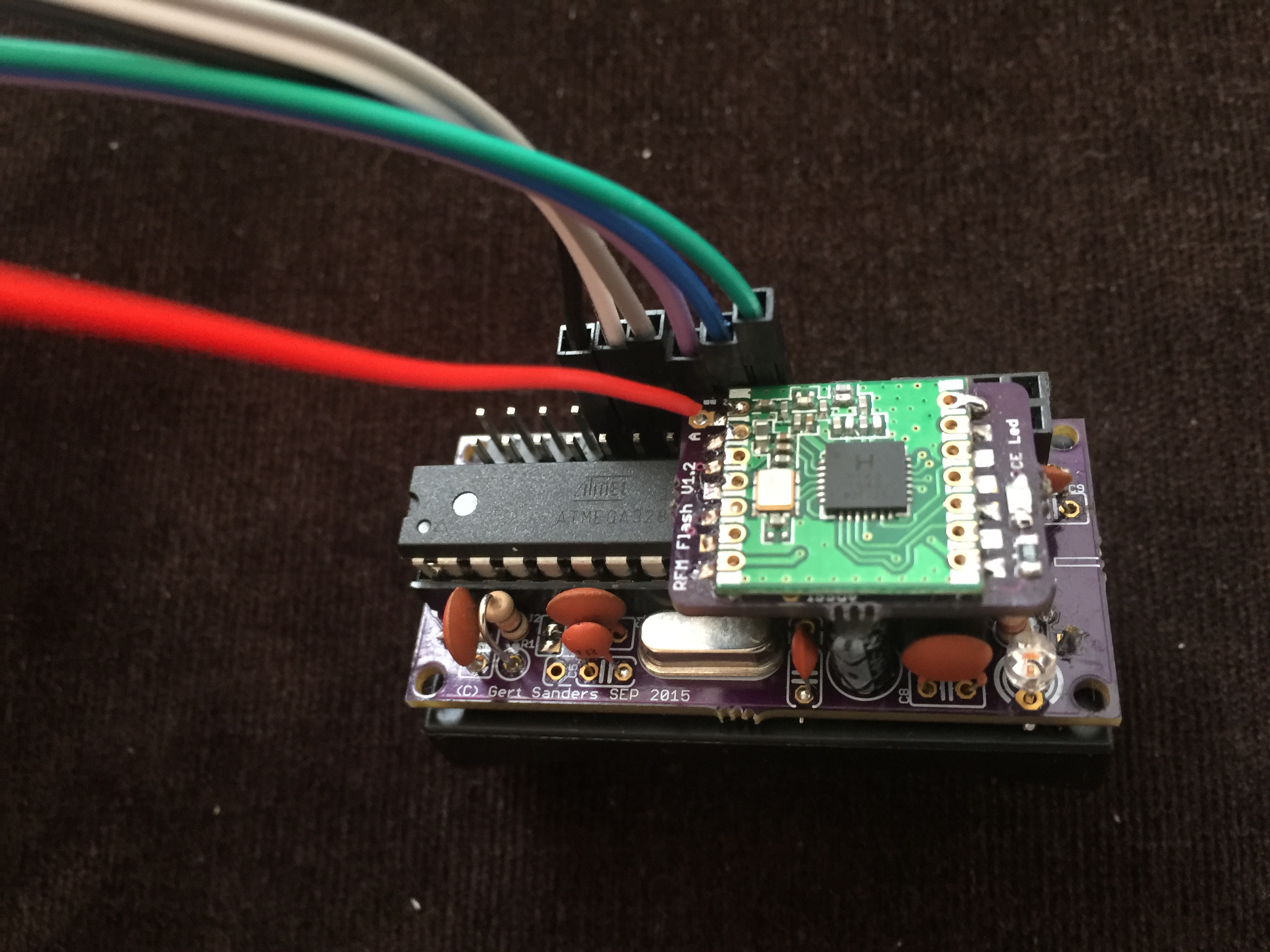
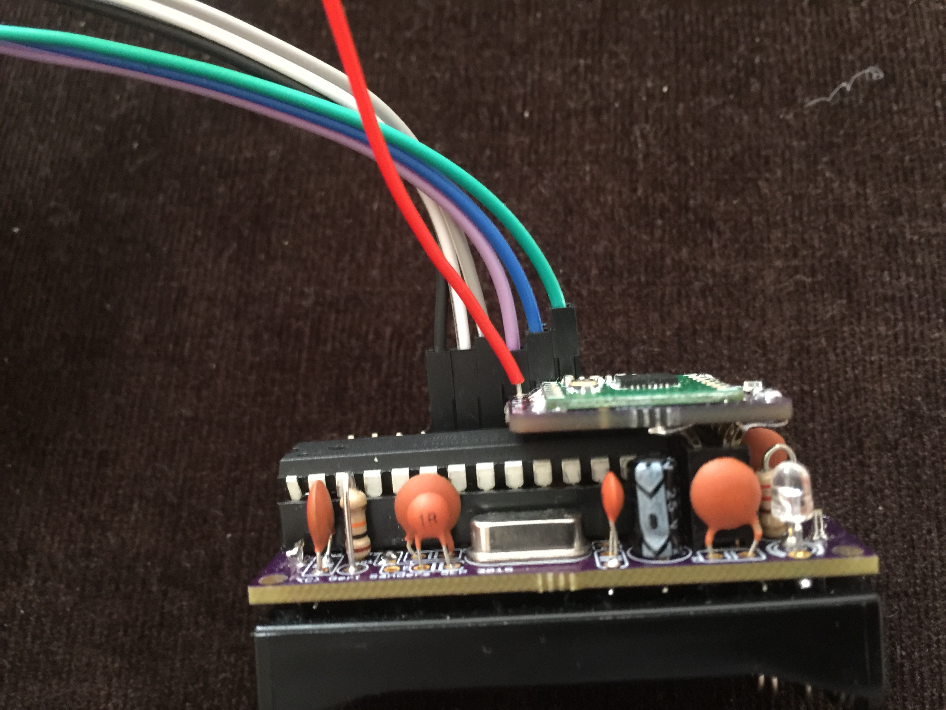
Adapter for RFM69 on NRF24L01+ pinout-header
-
Has anyone made or purchased an adapter to connect the RFM69 to a header with connections for nRF24L01+ ?
Such a header uses the following Arduino pins:
1: GND
2: 3V3
3: CE (pin 9)
4: CSN (pin 10 or SS)
5: SCK (pin 13)
6: MOSI (pin 11)
7: MISO (pin 12)
8: IRQ (not used)The RFM69 will need an interrupt pin, most likely D2 (pin 3 on the atmega328p).
-
@GertSanders There are these: https://oshpark.com/shared_projects/TKNcHTRl
Cheers
Al
-
@Sparkman : Super, thanks
-
@Sparkman Have you used them? Wonder what it involves. Soldering the RFM69 to the adaptor and plugging in the adaptor?
-
@GertSanders said:
Has anyone made or purchased an adapter to connect the RFM69 to a header with connections for nRF24L01+ ?
Such a header uses the following Arduino pins:
1: GND
2: 3V3
3: CE (pin 9)
4: CSN (pin 10 or SS)
5: SCK (pin 13)
6: MOSI (pin 11)
7: MISO (pin 12)
8: IRQ (not used)The RFM69 will need an interrupt pin, most likely D2 (pin 3 on the atmega328p).
Sounds like it might be good for retrofits. Ideally you'd pull out the NRF24L01+ and just plug-in the RFM69, and then everything would "just work" after a reboot. Unfortunately you might still have the interrupt wire to run to D2. Unless maybe that's the "unused" IRQ? To which pin on the Arduino does the IRQ socket already connect with? I would guess it's either D2 or D3. Most likely it's D2, in which case all is good. D9 wouldn't be needed anymore and could be freed up.
-
@shabba said:
@Sparkman Have you used them? Wonder what it involves. Soldering the RFM69 to the adaptor and plugging in the adaptor?
I have ordered them, but I have not used them. It is just the circuit board, so you will need to add headers and solder the rfm module to it.
Cheers
Al
-
@Sparkman Do let us know how you get on with them. Tempted to change over to RFM69 and this sounds like a potential route. Thanks!
-
I hope that the Serial gateway implementation on Raspberry PI also allows for a switch to RFM69. That all depends on how the IRQ pin needs te be treated.
On my board I provided for a jumper to connect the IRQ pin of the NRF24 to pin 2 of the atmega328 ( the INT0 pin). The MySensors library requires connection of IRQ to pin 2. But that would only cover the sensor side, not my gateway side yet. So here is hoping that we will have a solution of the gateway side as well.
.
-
Hi folks - Anyone use a good adaptor? I want to change all my sensors to RFM69 but have lots of boards that are designed for NRF24L01+
Thanks!
-
-
@hek Thanks but I do I order it? Put a few on a 5x5cm board on itead? Is there a file I can upload?
-
I would also like to know this. If you look at the openhardware.io site there is a link to the projects github page. There it is mentioned that he added a panelized version but I don´t understand witch file I need to upload to dirtycbs to order that version
-
You need to .zip all "combined" files. Each one describes a layer. The ".txt" for drills, ".gts"for top soldermask, etc... Fabhouse need all of them in one .zip
Here is explained which files you need for your .zip (in the Ordering Section)
http://dirtypcbs.com/about.php
-
Hmm, wait a bit ordering... I'm discussing some issues with PCBWay about the panelized version @tbowmo uploaded yesterday.
-
I've added a link to dirtypcb's on the project forum thread
-
I have ordered several adapters:
https://github.com/hallard/RFM12B-BreakOut
They are on oshpark.
Please check carefully which footprint you have:
- rfm12b /rfm69c(w) (the old rfm12 footprint)
- rfm69chw /rfm95* (lora footprint)
They are working fine @GertSanders on your nodes


I have also ordered @tbowmo adapter, but have not tried it.
-
How is the power consumption and the range with these modules ?
-
@GertSanders The range is BY FAR better. I am getting a very stable signal in the corners where nrf24l01+ has never worked. No more voodoo dancing trying to make nrf24l01+ work!
I have not measured the consumption yet as I would need a proper scope rather than using a multimeter. So I had to rely on this table:
-
very nice work. So the NRF2RFM69; will it work with the RFM69CHW chip at all? The reason I ask is, I have a lot of slimnodes on battery as well that I would like to switch radios for some better range (and hopefully, less failures on my network).
Thanks,
-
@drock1985 You do not need "H" radios on the nodes. I have the gateway with RFM69HCW (lora footprint the same as RFM95*) and the node with RFM69CW (RFM12B footprint). The issue with "H" radio is that it consumes much more to transmit - 130mA (vs 45mA for a non-H radio). 16.5cm insulated wire works really nicely. I did not notice much difference to SMA antenna though It does look sleeker.
The range on 433Mhz modules (one H and one non-H) is excellent. I'll to go outside to measure it. It covers the whole house without any dead zones.
-
By the way, anyone knows if there is an adapter for nrf24l01+ SMD to RFM69?
I am more interested in the lora footprint. I supposed this board (Flash Memory: 256Kb) on the kickstarter with RN2483 or RN2903 Module
-
Thanks @alexsh1, that answers that.
One other quick question. Other than ordering the PCB's from dirtypcb's; any other hardware for the board required? I know I will need wire for an antenna, but wasn't sure if there was any need for capacitors or resistors. I looked through the thread and found no parts list so i'm leaning towards no.
Thanks again,
-
@drock1985 I am not sure what board you would like to order from dirtypcb, there are no links in this thread. Under "hardware" what do you mean? Soldering iron? Components?
In relation to RFM69, you need the board itself and an antenna (a wire 16.5cm for 433Mhz or uFL-SMA connector with antenna). I have a capacitor on my node, but it was more designed for nrf24l01+. I do not think the capacitor is required for a 2xAA batteries powered node for RFM69 , but it is a matter of the trial-and-error. I have some NRF24L01+ working fine without caps.
-
More or less if there was any components to solder to the board (components). I know with the NRF you have to have a 4.7mf capacitor for the radio; wasn't sure if RFM was the same or not. The only component I see needing is the 2x4 pin header.
Thanks again.
-
@drock1985 OK, for the RFM69*** it depends how you are mounting it. On the photo above I mounted it instead of nrf24l01+ into 2x4 header. Not sure if you can see it from the photo. So i needed the following:
- The adapter RFM69CW to nrf24l01+
- Obviously, RFM69CW
- In my case for the adapter, I needed angled pins (2 rows by 4 to be soldered to the board) - http://www.aliexpress.com/item/10pcs-1x40-Pin-2-54mm-Right-Angle-Single-Row-Male-Pin-Header-Connector/32326283091.html?spm=2114.30010308.3.48.ewITwH&ws_ab_test=searchweb201556_10,searchweb201602_5_10037_10017_405_507_10033_406_10032,searchweb201603_2&btsid=5c8ce6ee-912d-494d-86b1-6fcd11e14771
- That's it.
As I said the cap is on the node and is there for nrf24l01+ (you can see it from the photo). I also had one cap, one resistor and one LED on the adapter (all 0805 SMD), but this is not compulsory.

-
Perfect, that answers that. Thanks again. Only complaint is the RFM is not as inexpensive as the NRF's. lol.
cheers,
-
@drock1985 I know, RFM95 is even more expensive!