nRF5 action!
-
Try it just print the time out then put it to sleep for a minute then print the time out again.
-
The problem must be this line but i don't speak nrf5.

			// (1000/32768)<<12 == 125
			MY_HW_RTC->CC[0] = max((ms<<12 / 125), 2);```
-
The only other thing it could be is the deletion of this line in the commit.
nrf5_rtc_event_triggered = false
-
MY_HW_RTC->CC[0] = max((ms<<12 / 125), 2);
Should be:-
MY_HW_RTC->CC[0] = max(((ms << 12) / 125), 2));
-
Just checked and it now returns 10002 for a sleep(10000).
Much better after the above alteration.
-
Epilog: I made the changes so that just prior to taking a measurement the sense pin is hwPinMode'd to an input pin, and then immediately after the measurement I disconnect it. Seems to be working, and without the usurious power drain I was experiencing previously.

-
@NeverDie said in nRF5 Bluetooth action!:
Epilog: I made the changes so that just prior to taking a measurement the sense pin is hwPinMode'd to an input pin, and then immediately after the measurement I disconnect it. Seems to be working, and without the usurious power drain I was experiencing previously.

Good news
So what is the current usage now when sleeping?
-
@rmtucker said in nRF5 Bluetooth action!:
@NeverDie said in nRF5 Bluetooth action!:
Epilog: I made the changes so that just prior to taking a measurement the sense pin is hwPinMode'd to an input pin, and then immediately after the measurement I disconnect it. Seems to be working, and without the usurious power drain I was experiencing previously.

Good news
So what is the current usage now when sleeping?About 6ua on this particular Ebyte nRF52832. I'm pretty sure it would be higher on my other Ebyte nRF52832, though I haven't measured it again. Haven't tested any additional ones as of yet.
-
@rmtucker very nice work, thanks for locating the problem.
It occurs because 12/125 will be evaluated before the bit shift. http://en.cppreference.com/w/c/language/operator_precedence for details.
-
@rmtucker said in nRF5 Bluetooth action!:
MY_HW_RTC->CC[0] = max((ms<<12 / 125), 2);
Should be:-
MY_HW_RTC->CC[0] = max(((ms << 12) / 125), 2));Thank you. This was the result of merging some commits. I haven't seen I reversed that change. I had tested the code before merging some commits into one.
Actually I check the result of sleep(511999) and sleep(512001). When it's finished I fix that in MySensors.
-
@scalz said in nRF5 Bluetooth action!:
@d00616 said in nRF5 Bluetooth action!:
Should I add a DISCONNECTED mode to hwPinMode()?
make sense to have it for input too.. i agree
What's the best name for this mode? DISCONNECTED or INPUT_DISCONNECTED. I prefer the first variant.
I have to play a little bit with the port modes. Maybe it saves some current when the serial port pins are put into the disconnected mode while sleeping.
-
@d00616 said in nRF5 Bluetooth action!:
Actually I check the result of sleep(511999) and sleep(512001). When it's finished I fix that in MySensors.
Is fixed in development branch.
https://github.com/mysensors/MySensors/pull/917
-
@d00616 said in nRF5 Bluetooth action!:
@scalz said in nRF5 Bluetooth action!:
@d00616 said in nRF5 Bluetooth action!:
Should I add a DISCONNECTED mode to hwPinMode()?
make sense to have it for input too.. i agree
What's the best name for this mode? DISCONNECTED or INPUT_DISCONNECTED. I prefer the first variant.
I have to play a little bit with the port modes. Maybe it saves some current when the serial port pins are put into the disconnected mode while sleeping.
agree too for the first one should be enough :simple_smile:
yes, for lower power consumption, better disconnect pins which are not needed.
it's the same for a simple 328p though (setting the right pin states).
-
As a follow-up to rmtucker's line of inquiry, what is currently the shortest deep sleep that's supported? Is it one millisecond, or something else?
-
@NeverDie
Theoretically it is 2 clock ticks at 32768khz so 0.000061035secs i think.
But how long it takes to go into sleep mode and come out of sleep mode i am not sure.
But of course the sleep function only allows millis.
-
@NeverDie said in nRF5 Bluetooth action!:
As a follow-up to rmtucker's line of inquiry, what is currently the shortest deep sleep that's supported? Is it one millisecond, or something else?
Why do you need this type of short sleeps?
Sleep is for battery powered devices. A device that wakes up more than 1000 times in the second might be hard to drive with a battery.
@rmtucker said in nRF5 Bluetooth action!:
@NeverDie
Theoretically it is 2 clock ticks at 32768khz so 0.000061035secs i think.This is correct.
But how long it takes to go into sleep mode and come out of sleep mode i am not sure.
It's simple to evaluate with micros() before and after a sleep().
-
I haven't yet upgraded to the current version, so maybe this is moot (?), but the following code in a loop:
  digitalWrite(TEST_PIN,HIGH);
  sleep(100); // Sleeps for 100ms
  digitalWrite(TEST_PIN,LOW);
  sleep(100); // Sleeps for 100ms
holds the TEST_PIN first HIGH for 250ms and then LOW for 250ms. That means 150ms of sleep overhead, which seems like a lot.
I measured the length of time the TEST_PIN is HIGH or LOW using an oscilloscope. Ran it on an Ebyte nRF52832.
-
Nevermind. I just now upgraded to the current versions, and it seems to be fixed.
-
So, with the current libraries and an Ebyte nRF52832 that's using its external crystal oscillator, I'm now measuring the sleep overhead as being 260us. I expect that may be even less if using the internal 32768Hz resonator.
-
I tried measuring the sleep overhead with the Ebyte nRF52832 running on its internal resonator, and surprisingly it wasn't that much faster: it appears to be about 220us.
Here's the test script:
#include <MySensors.h>

#define TEST_PIN 19  // (P0.19)

void setup()
{
  hwPinMode(TEST_PIN, OUTPUT_H0H1);
  digitalWrite(TEST_PIN, LOW);
}

void loop() {
  digitalWrite(TEST_PIN,HIGH);
  sleep(1); // Sleeps for 1ms
  digitalWrite(TEST_PIN,LOW);
  sleep(1); // Sleeps for 1ms
}
Here's the scope capture:
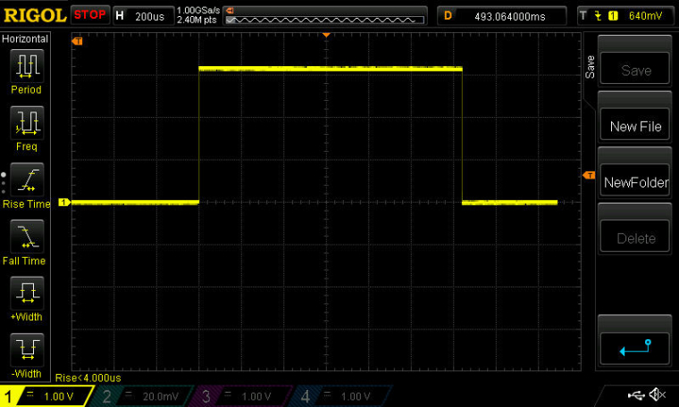
Of course, this assumes (?) that the mcu sleeps for exactly 1ms, and during the extra 220us it is either ramping down or ramping up.
BTW, I don't anticipate sleeping for a mere 1ms at a time. However, to get a good measurement of the overhead using the oscilliscope I had to set the sleep period that low.
I can, however, well imagine having a use for sleep periods lasting 100ms.
-
Anyhow, it's not academic, as the plan is to approximate the "listen-mode" of an RFM69, but using the nRF52832. For that to be power efficient, I need the mcu to wake-up and fall-asleep very, very fast. For comparison, an atmega328p can wake-up in 3.8usec.
On page of the nRF52832 datasheet, it advertises:
Fast wake-up using 64 MHz internal oscillator
However, I'm not sure how to set that up. There's no menu check-box for that on the Arduino IDE tools menu like there is for the 32768Hz internal resonator. On the other hand, I'm not sure that it matters, because apparently the 64Mhz external crystal, which is what's slowing down the wake-up, is required to operate the radio.
-
Here's the current drain through a 1-ohm resistor:
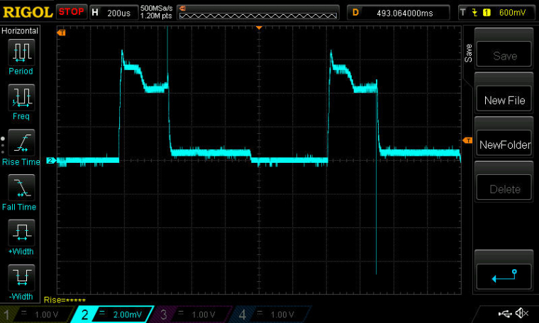
i.e. 1mv=1ma.As you can see, there's a rather long tail before it finally falls asleep.
Here is the same, but superimposed onto the TEST_PIN capture:
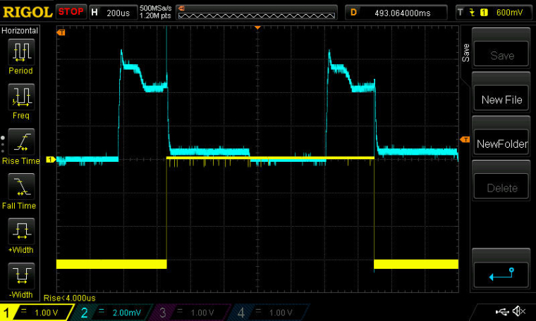
-
Good news. It appears that DCDC is already implemented on the Ebyte nRF52832 and working automatically!
Just for grins, I decided to measure the Tx time and current draw from sending a 13 byte payload in a packet, and I was happily surprised to see how low the current draw was:
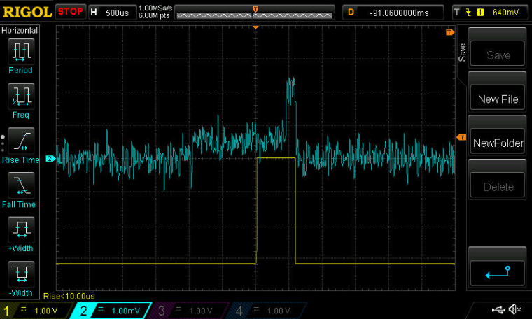
The yellow trace marks the start and stop of the packet transmission process from a software point of view, but the blue trace measures the current (as before 1mv=1ma). As you can see, the transmission current never seems to rise above 2.5ma. The only (?) explanation I can think of is that DCDC must be working. Right? Tx power is set to be 4dbm.
It would be great if someone else would confirm/refute the measurement.
-
@NeverDie said in nRF5 Bluetooth action!:
It would be great if someone else would confirm/refute the measurement.
I don't think it's possible, from the datasheet peak current is 7.7mA at +4dB with DCDC enabled with 3V power supply.
Current gain from 3V=>1.7V DCDC conversion is already included in this measurement so you should not be able to go lower.How did you make your measurement across the resistor ?
-
@Nca78
You're right. It didn't ring true, so I setup some different capture hardware, and this time the image is a lot crisper:
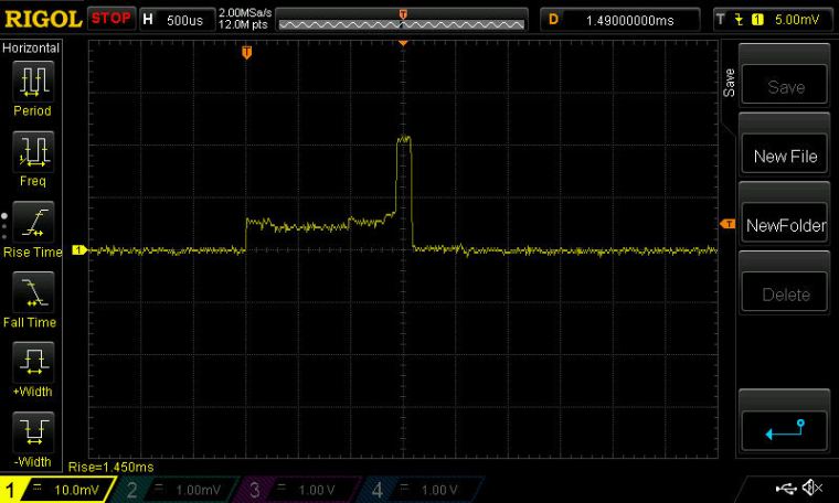
This time I powered it from a 3.3v supercap and with the 1 ohm resistor soldered securely onto a PCB, with the o-scope leads on either side of it.So, sadly, it doesn't look DCDC after all, because on this capture the peak is exceeding 20ma.

It's interesting how lengthy (and energy intensive) the phase is that's just prior to the transmission itself. I presume that's mainly just the PLL coming up to speed? It looks as though the actual current expended in the prelude exceeds that of the actual Tx proper!
I'm guessing that in the earlier scope capture, the probe must have slipped into 10x mode, because the shape is similar, just proportionately reduced by roughly that factor.
-
BTW, I assembled my third board now, and it sleeps at about 9.9ua. The first one sleeps at about 6ua, and the second at about 9ua. It would be interesting to know why the first board is so much less, but it seems that about 9-10ua is the more typical number. That also seems to agree with @d00616 's measurements.
-
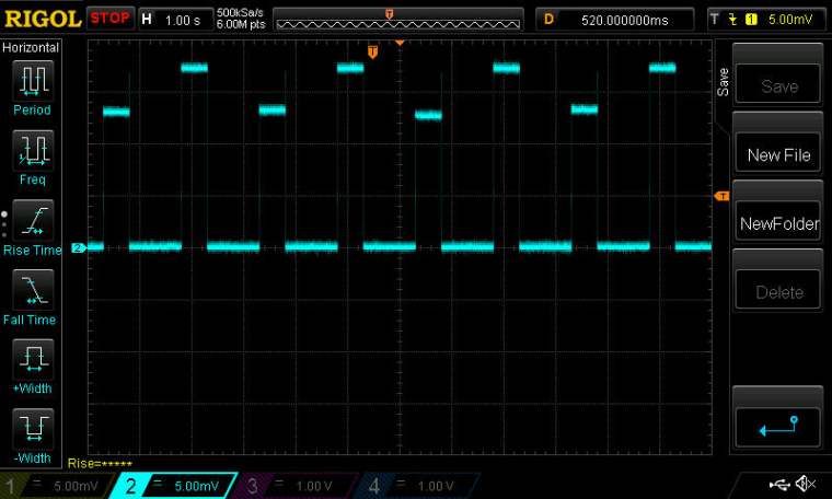
Interestingly enough, you can put the radio into receive mode and then sleep the mcu with the radio still in receive mode. Here's a screenshot of current consumption while receiving, where I alternate between leaving the mcu active or sleeping it (each for duration of 500ms). In-between, I sleep everything (both radio and mcu) for 1 second:
-
Here's the mode that I'm most interested in: Putting the radio into Rx for about 1ms per 100ms interval to listen for remote commands. The rest of the time everthing (both radio and mcu) are in deep sleep waiting for the RTC to wake them up.
Here's a close-up of the current drawn during that roughly 1ms interval:
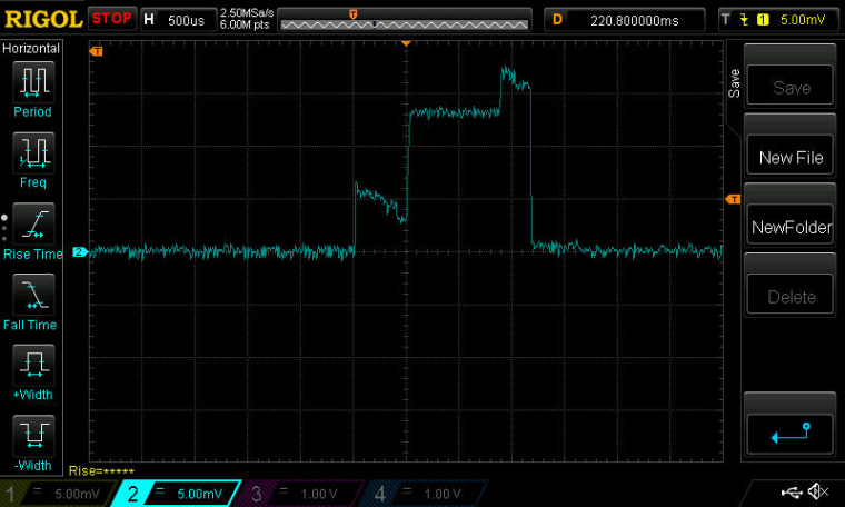
I ran this just now, and my solar setup can easily handle this load during the daytime, even from deep indoors far from the windows. This was the scenario that really stressed the RFM69+atmega328p combo when I tried doing it using the RFM69's listen mode. I'll see tonight how the 10F supercap handles the load without any solar assist.

Because of the nRF52839's 2Mbps datarate, I can probably cut the listen window down substantially from 1ms to much less (much less than would be possible with an RFM69, due to its maximum of 300kbps datarate), but for ease of programming I'm starting with this.
-
@NeverDie said in nRF5 Bluetooth action!:
Here's the mode that I'm most interested in: Putting the radio into Rx for about 1ms per 100ms interval to listen for remote commands. The rest of the time everthing (both radio and mcu) are in deep sleep waiting for the RTC to wake them up.
When you take a look into the PPI section, you are able to let the CPU sleep until a radio packet is received. With PPI, the listen mode can be activated and deactivated without CPU interaction.
The nRF5 MCUs are able to to a lot of things without waking up the CPU. That's a really cool feature.
-
@d00616 said in nRF5 Bluetooth action!:
@NeverDie said in nRF5 Bluetooth action!:
Here's the mode that I'm most interested in: Putting the radio into Rx for about 1ms per 100ms interval to listen for remote commands. The rest of the time everthing (both radio and mcu) are in deep sleep waiting for the RTC to wake them up.
When you take a look into the PPI section, you are able to let the CPU sleep until a radio packet is received. With PPI, the listen mode can be activated and deactivated without CPU interaction.
The nRF5 MCUs are able to to a lot of things without waking up the CPU. That's a really cool feature.
Sounds like it has potential. Any demo code for this? The datasheet seems a bit sketchy.
-
@NeverDie said in nRF5 Bluetooth action!:
@d00616 said in nRF5 Bluetooth action!:
@NeverDie said in nRF5 Bluetooth action!:
Here's the mode that I'm most interested in: Putting the radio into Rx for about 1ms per 100ms interval to listen for remote commands. The rest of the time everthing (both radio and mcu) are in deep sleep waiting for the RTC to wake them up.
When you take a look into the PPI section, you are able to let the CPU sleep until a radio packet is received. With PPI, the listen mode can be activated and deactivated without CPU interaction.
The nRF5 MCUs are able to to a lot of things without waking up the CPU. That's a really cool feature.Sounds like it has potential. Any demo code for this? The datasheet seems a bit sketchy.
These are some snippets of the radio code. There are fully useable PPI and some predefined. For fully useable PPI into the EEP register, you put the address of an EVENT register and in the TEP register, you put the pointer to an TASK register.
   /** Configure PPI (Programmable peripheral interconnect) */
    // Start timer on END event
    NRF_PPI->CH[NRF5_ESB_PPI_TIMER_START].EEP = (uint32_t)&NRF_RADIO->EVENTS_END;
    NRF_PPI->CH[NRF5_ESB_PPI_TIMER_START].TEP = (uint32_t)&NRF5_RADIO_TIMER->TASKS_START;
    // Disable Radio after CC[0]
    NRF_PPI->CH[NRF5_ESB_PPI_TIMER_RADIO_DISABLE].EEP = (uint32_t)&NRF5_RADIO_TIMER->EVENTS_COMPARE[0];
    NRF_PPI->CH[NRF5_ESB_PPI_TIMER_RADIO_DISABLE].TEP = (uint32_t)&NRF_RADIO->TASKS_DISABLE;
    ...
    // Set PPI
     NRF_PPI->CHENSET = NRF5_ESB_PPI_BITS;
    ...
  // Clear PPI
    NRF_PPI->CHENCLR = NRF5_ESB_PPI_BITS;
Then you have to enable or disable the register. It could be necessary to reset the events. You can use the NRF_RESET_EVENT macro to do this job.
NRF_RESET_EVENT(NRF5_RADIO_TIMER->EVENTS_COMPARE[0]);
-
I have a brute force version of "listen mode" working using just the libraries, but I have to re-initialize the radio after each cycle because it appears to lose its settings every time I sleep it.
Anyway, finding a way to add DCDC mode to these modules will probably have the biggest near-term impact on current consumption. That said, I'm sure plenty of energy savings can also be found by honing the code.
-
Actually, even just sleeping the MCU with a simple command like:
sleep(100);is apparently enough to require a re-init of the radio afterward. Not sure why that would be.
-
Comparing Figures 169 and 170 in the nRF52832 datasheet, it looks as though simply adding two inductors in series between DCC and DEC4 should be all that's needed to provide the needed hardware support for DC/DC. Looks as though the 10uH inductor also needs to be able to support a minimum of 50ma, according to the BOM (Table 145).
So, is it as simple as that together with enabling register DCDCEN? Or, is there anything more to it?
-
Yes. This is like that. I use 2 inductors (better) in serie. Why more complicated

-
@NeverDie said in nRF5 Bluetooth action!:
Actually, even just sleeping the MCU with a simple command like:
sleep(100);is apparently enough to require a re-init of the radio afterward. Not sure why that would be.
sleep() deinitializes the transport with transportDisable(). This results in power down the radio.
At the moment I review the ESB code. I think the nRF5 is 12-13µs after an nRF24 in RX mode and 432µs before an nRF24 in TX. This can result in unstable connections when debug messages are disabled.
-
Sort-of working. Here's a screen shot with the DC/DC modification. Compare to the earlier one above:
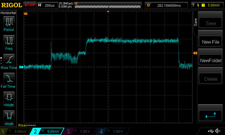
Probably non-optimal placement of the inductors: between the DCC and DEC4 pins on my breakout board for the nRF52832.This is reason enough to do an new version of the breakout for the Ebyte module to improve the inductor positioning.
Here's the enable code:
NRF_POWER->DCDCEN=1; //enable the DCDC voltage regulator as the default.If it's this easy, I'm just surprised that the module makers haven't included it. The difference in build cost is de minimus, but the difference in delivered value is huge.
Also, it sounds like I'll have to write a variant of sleep that sleeps just the MPU while leaving the radio in receive mode. That's an easy win to improve the current consumption.
-
Good news! I went back and re-rechecked using an un-modified Ebyte module, and, indeed, this time I'm sure that the DCDC inductors are already on it! What follows is the proof. Here is the current drawn when the above DCDCEN is enabled on an unmodified Ebyte module: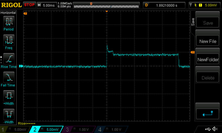
Now, here is the current drawn with the exact same script on the exact same unmodified Ebyte module, but with the DCDCEN line of code commented out: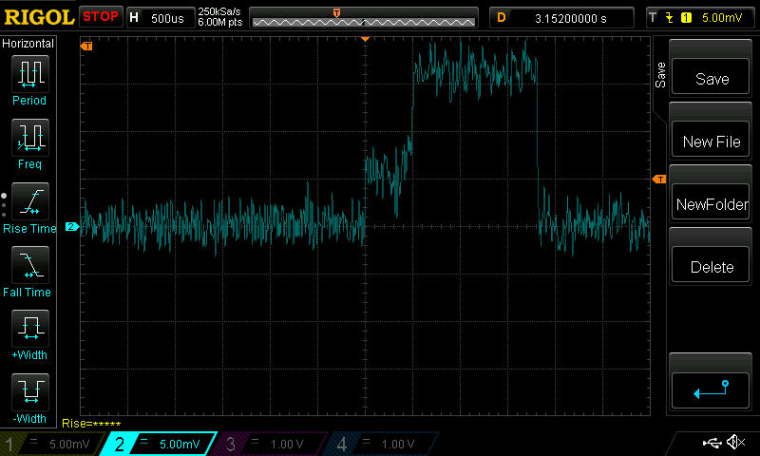
QED.
As you can see, the savings in current consumption are considerable with the DCDC enabled![Edit: although looking at it again, the timescale seems way off. Argh. Something still isn't right.]
-
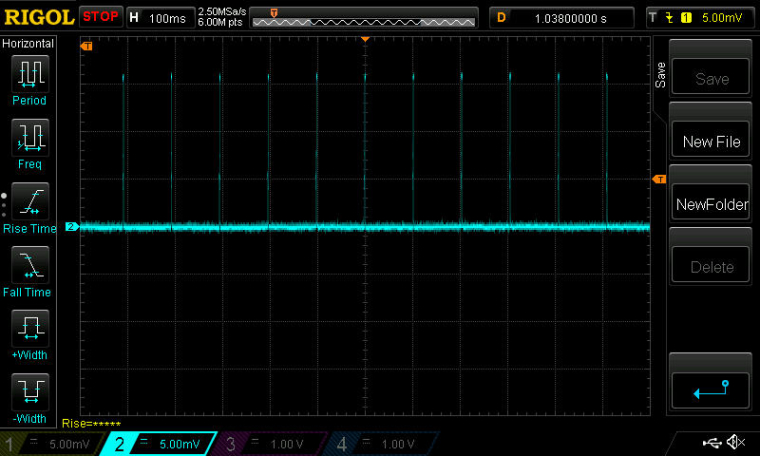
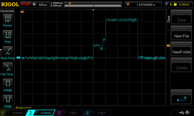
Scratch the preceeding post. I redid it more carefully this time, and I believe it confirms that the Ebyte module does not have the two inductors required for DC/DC mode.
Here is the current drawn by an unmodified Ebyte nRF52832 module which is programmed to be receiving for about 1.5ms every 100ms:
-
Here is what happens with exactly the same hardware (no inductors yet added), but with DCDCEN enabled:
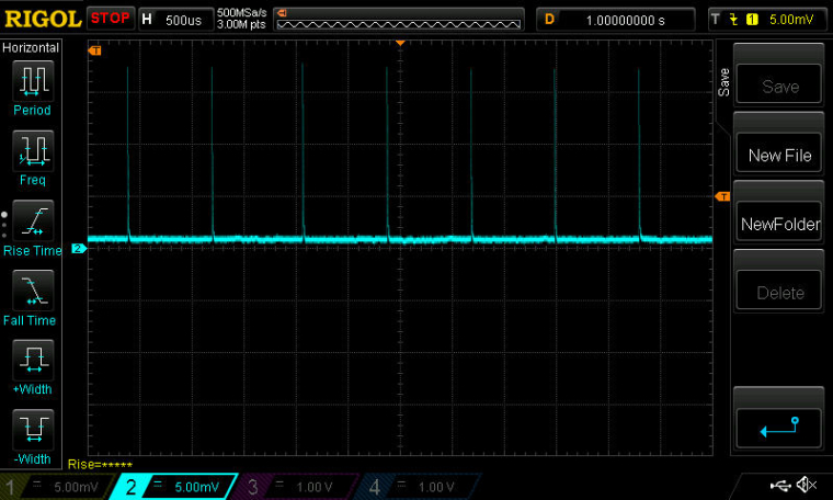
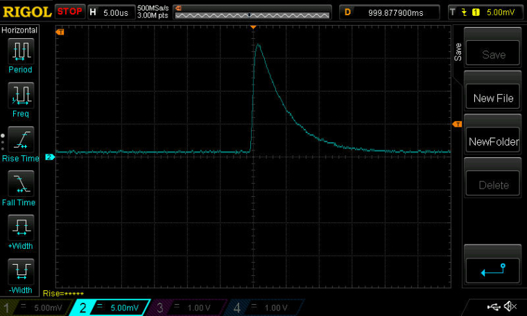
It basically seems caught in a boot loop.
-
Now, adding the two inductors between DCC and DEC4, and re-measuring, we get:
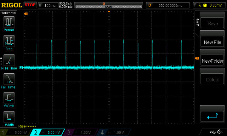
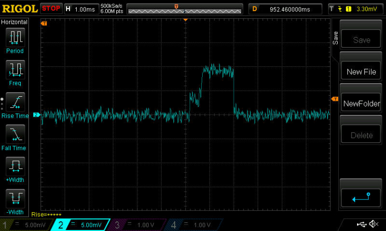
No less importantly, it does receive and decode packets!
Conclusion: Ebyte nRF52832 modules don't come with the DC/DC inductors already installed. However, they can be added, resulting in some current reduction.
-
I've baked these findings into a new breakout board for the Ebyte nRF52832:
https://www.openhardware.io/view/471
The new breakout board will enable the module to work in DC/DC mode.
-
I may have found a clue as to why the reset pin (pin0.21) on the nRF52832 isn't working.
On the nRF52832 DK, I read the following register values:
PSELRESET[0]=21
PSELRESET[1]=21which is as expected. However, on the Ebyte nRF52832 module, I read those register values as:
PSELRESET[0]=4294967295
PSELRESET[1]=4294967295which makes no sense. The values match, but they don't correspond to a pin number that can represent RESET.
These two registers are described in the nRF52832 datasheet.
-
@NeverDie not sure if you've already noticed, but 4294967295 is the maximum value for an unsigned 32-bit integer. So the value is 0xFFFFFFFF. That often means uninitialized. I don't know why it would be uninitialized though.
-
Maybe because they just never were?
Those particular registers are "The user information configuration registers (UICRs) are non-volatile memory (NVM) registers for configuring user specific settings." So, it would seem that initializing them just once would be enough, since they're non-volatile.In any case, good catch! It explains both why they are that value and also why they match.
-
@NeverDie said in nRF5 Bluetooth action!:
4294967295
Also, since 4294967295 equals 0xFFFFFFFF, then bit 31 is a '1', which, according to the datasheet, means the pin is disconnected (see section 14.1.60 PSELRESET[0] of the datasheet for the detail].
-
@mfalkvidd said in nRF5 Bluetooth action!:
So the value is 0xFFFFFFFF. That often means uninitialized. I don't know why it would be uninitialized though.
There's a chance we may have unwittingly done it ourselves! Remember back to when we were doing an explicit "Erase All"? From the datasheet:
11.5 Erase all
When erase is enabled, the whole Flash and UICR can be erased in one operation by using the ERASEALL
register.Furthermore, from page 29 of the datasheet:
After erasing UICR all bits in UICR are set to '1'.
-
@NeverDie said in nRF5 Bluetooth action!:
@mfalkvidd said in nRF5 Bluetooth action!:
So the value is 0xFFFFFFFF. That often means uninitialized. I don't know why it would be uninitialized though.
There's a chance we may have unwittingly done it ourselves! Remember back to when we were doing an explicit "Erase All"? From the datasheet:
This is part of the arduino-nrf5 code -> https://github.com/sandeepmistry/arduino-nRF5/blob/dc53980c8bac27898fca90d8ecb268e11111edc1/cores/nRF5/SDK/components/toolchain/system_nrf52.c#L156
I don't have any idea why this is not included in the binary. When the reset menu is selected then "-DCONFIG_GPIO_AS_PINRESET" is given to gcc.
When system_nrf52.c is completely ignored, then the erratas are not handled.
-
Here is some verbose code which properly sets the registers to use pin P0.21 as the RESET pin:
Serial.println("Testing...");
delay(10000);  //give preparation time to open serial tty
Serial.print(counter);
Serial.print(", PSELRESET[0]=");
Serial.println(NRF_UICR-> PSELRESET[0]);
Serial.print(counter++);
Serial.print(", PSELRESET[1]=");
Serial.println(NRF_UICR-> PSELRESET[1]);

Serial.println();
Serial.println("Write-enabling CONFIG.");
NRF_NVMC->CONFIG=1;  // Write enable the UICR

Serial.println();
Serial.println("Now designating pin pO.21 as the RESET pin.");
NRF_UICR-> PSELRESET[0]=21;  //designate pin pO.21 as the RESET pin
NRF_UICR-> PSELRESET[1]=21;  //designate pin pO.21 as the RESET pin

Serial.println();
Serial.println("Confirming that RESET pin assigment took hold:");
Serial.print(counter);
Serial.print(", PSELRESET[0]=");
Serial.println(NRF_UICR-> PSELRESET[0]);
Serial.print(counter++);
Serial.print(", PSELRESET[1]=");
Serial.println(NRF_UICR-> PSELRESET[1]);

Serial.println();
Serial.println("Return CONFIG to read-only mode.");
NRF_NVMC->CONFIG=0;  // Put the UICR back into read-only mode.
Running it once seems to be good enough, unless there were to occur another "Erase All" or "Burn bootloader" event.
Here is the output from running the code which shows that it succeeded:
Testing...
0, PSELRESET[0]=4294967295
0, PSELRESET[1]=4294967295

Write-enabling CONFIG.

Now designating pin pO.21 as the RESET pin.

Confirming that RESET pin assigment took hold:
1, PSELRESET[0]=21
1, PSELRESET[1]=21

Return CONFIG to read-only mode.
-
Until a more elegant solution can be found, I'm using this in the setup() routine as the workaround:
  if (((NRF_UICR-> PSELRESET[0])==0xFFFFFFFF) && ((NRF_UICR-> PSELRESET[1])==0xFFFFFFFF)) { //if the two RESET registers are erased
    NRF_NVMC->CONFIG=1;  // Write enable the UICR
    NRF_UICR-> PSELRESET[0]=21;  //designate pin P0.21 as the RESET pin
    NRF_UICR-> PSELRESET[1]=21;  //designate pin P0.21 as the RESET pin
    NRF_NVMC->CONFIG=0;  // Put the UICR back into read-only mode.
  }
The code has the positive virtue of not writing to the RESET rregisters unless both registers are erased. That helps ensure that the non-volatile memory does not get worn out prematurely.
-
@NeverDie said in nRF5 Bluetooth action!:
Until a more elegant solution can be found, I'm using this in the setup() routine as the workaround:
  if (((NRF_UICR-> PSELRESET[0])==0xFFFFFFFF) && ((NRF_UICR-> PSELRESET[1])==0xFFFFFFFF)) { //if the two RESET registers are erased
    NRF_NVMC->CONFIG=1;  // Write enable the UICR
    NRF_UICR-> PSELRESET[0]=21;  //designate pin P0.21 as the RESET pin
    NRF_UICR-> PSELRESET[1]=21;  //designate pin P0.21 as the RESET pin
    NRF_NVMC->CONFIG=0;  // Put the UICR back into read-only mode.
  }
The code has the positive virtue of not writing to the RESET rregisters unless both registers are erased. That helps ensure that the non-volatile memory does not get worn out prematurely.
Good news! I've confirmed that doing this does indeed solve the problem I previously had with the EByte nRF52832 module not reacting to a reset on pin P0.21. After inserting the above code block into the nRF52832's setup() routine, I can now, using ESP-LINK, remotely reset an nRF52832 module:
https://www.openhardware.io/view/443/nRF52832-ESP-LINK-Shield-for-ESP8266-Wemos-D1-Mini
-
With that issue now settled, I'm moving on to a different topic: what happens if you put the radio into Tx mode, but with an empty buffer (i.e. nothing to send)? In this scenario an RFM69 transmits a continuous pre-amble, and I'm wondering whether the nRF52832 does the same?
With an empty buffer, does it transmit anything at all? Anyone happen to know?The reason I ask is that I want to program the radio to send a continuous signal so as to quickly wake-up a receiver. With packets, there's the lag time of receiving and decoding the packet, rather than just reacting to a high RSSI. In this way, I can use much narrower listen windows and thereby save a lot of current consumption.
-
According to the datasheet, the typical RSSI sample period is just 0.25us. However, what spoils that a bit is that the radio has to come up to speed beforehand.
Anyhow, on the receive side, I now have at least that much working.
-
It looks as though the start-up time for the radio is about 390us. So, it does save a lot of current to first check the RSSI level rather than to always listen for a packet.
-
When I measure RSSI on the nRF52832, I get what seems like a rather odd range of values: between about 94 and 127. If I have no other nodes transmitting, then the RSSI is generally around 100. If I set up another node which deliberately transmits on the same channel, then the RSSI is pegged at 127.
Is that what others here are also seeing? Here's the test code:
uint8_t theRSSI;
void loop() {

NRF_RADIO->TASKS_RXEN=1;  //start revving up the receiver
while (!(NRF_RADIO->EVENTS_READY)) {} //busy-wait until radio ready to receive
NRF_RADIO->TASKS_RSSISTART=1;  //Take exactly one RSSI sample
while (!(NRF_RADIO->EVENTS_RSSIEND)) {}  //Busy-wait until RSSI sample is completed.
theRSSI = NRF_RADIO->RSSISAMPLE;

Serial.println(theRSSI);
Serial.flush();
sleep(1000);
}
-
Unfortunately, when I use the above code block and test the current using an oscilliscope, it becomes clear that the radio never actually goes to sleep:
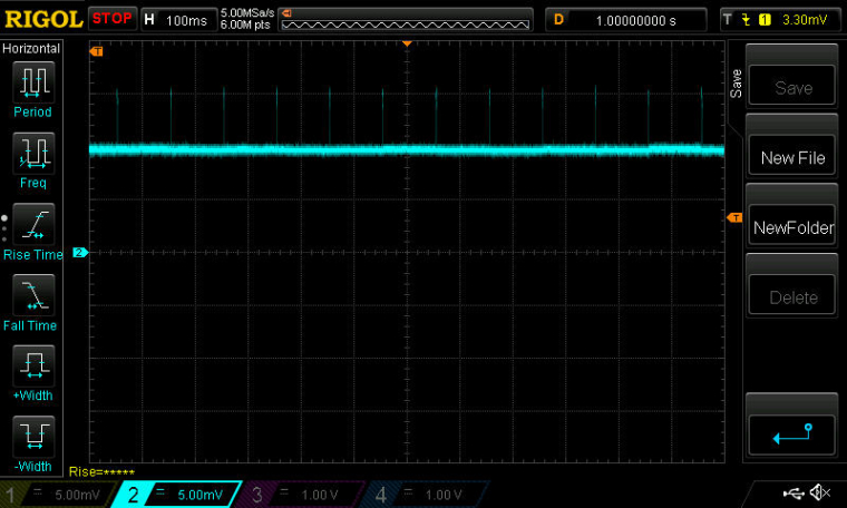
So, to do that, I add the line:NRF_RADIO->TASKS_DISABLE=1; //turn-off the radiojust prior to sleep(100). Doing that largely eliminates the current drain while sleeping:
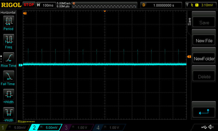
However, if I do that, then the RSSI that gets reported is always 127. Why? Do I need some other way to check the radio states? Maybe STATE from section 23.14.25 STATE of the datasheet would work better?
-
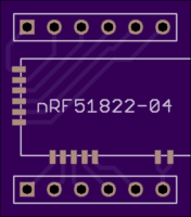
Found a breakout board for the nRF51822-04: https://oshpark.com/shared_projects/zqDQaykJ
-
The datasheet is possibly a bit misleading when it says:
For the RSSI sample to be valid the radio has to be enabled in receive mode (RXEN task) and the reception
has to be started (READY event followed by START task).I'm finding that the radio needs to be in either RXIDLE state or RX state to get a plausible RSSI measurement. I can't get a reasonable RSSI measurement while within the RXRU state.
-
@NeverDie said in nRF5 Bluetooth action!:
The datasheet is possibly a bit misleading when it says:
For the RSSI sample to be valid the radio has to be enabled in receive mode (RXEN task) and the reception
has to be started (READY event followed by START task).I'm finding that the radio needs to be in either RXIDLE state or RX state to get a plausible RSSI measurement. I can't get a reasonable RSSI measurement while within the RXEN state.
In the ESB code, I use the bitcounter event to start the rssi sample task via PPI. The results are looking plausible.
-
I've found that I get a slightly stronger RSSI signal by about 3dB if I measure it while in the RX state rather than the RXIDLE state.
-
@d00616 said in nRF5 Bluetooth action!:
In the ESB code, I use the bitcounter event to start the rssi sample task via PPI. The results are looking plausible.
Do you know of any good PPI tutorials? The datasheet seems awfully skimpy on its explanation of exactly how to use it.
Right now I have RSSI triggers working on the receiver (presently using the MCU, not PPI), but it takes 1400 samples to guarantee not missing any transmissions. That's because of the gap between single shot packets when they get sent. If I can reduce that to one sample, by finding a way to make a transmitter transmit continuously, then that will save a lot of energy on the receiver.
There is a way to do more rapid fire transmission of packets, so that would be the fall-back plan if I can't find a way to, for example, send a continuous preamble.
-
Answering my own question: it turns out that if you enter into TX mode without any payload, it just sends a null packet and returns to TXIDLE. So, it is not like the RFM69, which would simply send an indefinitely long preamble until there's a payload to send.
The goal is to close the gap between packets as much as possible. So, I'm getting some improvement by just immediately switching back into TX mode (to send another null packet) the moment I've confirmed that TXIDLE state has re-occured.
-
As it turns out, using the above method packs the null packets so tightly that I can rely on a single RSSI measurement (instead of 1400 of them) to guarantee that a transmission won't be missed. So, the goal is achieved.
It sounds as though combining PPI with this would drive the energy consumption even lower!

-
@NeverDie Thank you sharing your experience here. It helps me of better understanding some nRF5 internals. It would be awesome if you share your code.
@NeverDie said in nRF5 Bluetooth action!:
Do you know of any good PPI tutorials? The datasheet seems awfully skimpy on its explanation of exactly how to use it.
To understand PPI you have to be in mind that nearly everything is driven by tasks and events. If you want to do something, you have to start a task like 'NRF_RADIO->TASKS_TXEN=1'. If a task ends it generates an event like 'NRF_RADIO->EVENTS_READY'. You can replace NRF_RADIO with another periphery the registers have an equal naming scheme.
For an event an Interrupt can be enabled with the NRF_RADIO->INTENSET register. Each event correspondents with a bit in that register. In an interrupt, you have to reset the NRF_RADIO->EVENTS_READY register to 0 to allow triggering a new interrupt. For compatibility, you can use the NRF_RESET_EVENT macro in interrupts. This reads back the register on nRF52 to avoid caching effects. Interrupts doesn't matter for PPI

The next fine thing are Shortcuts. Shortcuts are limited to the same peripheral unit. Bits in the NRF_RADIO->SHORTS register are corresponding to a connection between an event and a test. If the event is triggered the task is started. This allows to trigger things like send an packet after the radio is ready. To use this, you have to enable the shortcut in the NRF_RADIO->SHORTS register.
To break the limits of shortcuts, there is the PPI unit with 32 channels. Some of the channels are predefined but interesting to see how things are implemented with BLE. The other PPI channels are flexible. To use one of these channels, you have to write a pointer of your event register, like '(uint32_t)&NRF_RADIO->EVENTS_END' to the NRF_PPI->CH[YOUR_CHANNEL].EEP register and a pointer to your task you want to start in the NRF_PPI->CH[YOUR_CHANNEL].TEP register like '(uint32_t)&NRF_TIMER0->TASKS_START'. Then you have to enable the PPI channel by setting the corresponding bit like 'NRF_PPI->CHENSET |= (1 << COUR_CHANNEL)' that's all.
The nRF52, but not the nRF52 comes with NRF_PPI->FORK[YOUR_CHANNEL].TEP registers. in my reading you can start a second task with this register like writing to NRF_PPI->CH[YOUR_CHANNEL].TEP.
I have no idea about using the PPI Groups.
Arudino provides a PPI library for the primo: http://cdn.devarduino.org/learning/reference/ppi I think we have to use this library to be compatible in the future. I hope there is a chance to port things to arduino-nrf5 back.
Edit: The arduino PPI library is not flexible enough to support radio events.

-
Thanks! At least notionally, the PPI sounds excellent. Presently, if I want to move the radio into a particular state which takes a few state changes to get there, using the MCU with a conservative coding style, I have to initiate the first state change, then busy-wait until the new state is confirmed, then make the next state-change, etc. It sounds as though the PPI is a good fit for this, because it would eliminate the busy-waits. It would automatically transition from one state to the next using just the interrupt scheme you outlined until the target state is reached. Well, at least in theory. Meanwhile the CPU could be doing other things or sleeping. This does sound like a definite improvement, especially for more efficient control over the radio.

-
@d00616 said in nRF5 Bluetooth action!:
@NeverDie Thank you sharing your experience here. It helps me of better understanding some nRF5 internals. It would be awesome if you share your code.
Here it is:
#include <MySensors.h>
#include <nrf.h>

void setup()
{
  NRF_POWER->DCDCEN=1;  //enable the DCDC voltage regulator as the default.

  //guarantee RESET pin is working
  if (((NRF_UICR-> PSELRESET[0])==0xFFFFFFFF) && ((NRF_UICR-> PSELRESET[1])==0xFFFFFFFF)) { //if the two RESET registers are erased
    NRF_NVMC->CONFIG=1;  // Write enable the UICR
    NRF_UICR-> PSELRESET[0]=21;  //designate pin P0.21 as the RESET pin
    NRF_UICR-> PSELRESET[1]=21;  //designate pin P0.21 as the RESET pin
    NRF_NVMC->CONFIG=0;  // Put the UICR back into read-only mode.
  }

  NRF_RADIO->FREQUENCY=123;
  NRF_RADIO->MODE=2;  //set 250kbps datarate.  May as well stretch out the NULL packet as much as possible.

  NRF_RADIO->TASKS_DISABLE=1;  //turn-off the radio to establish known state.
  while (NRF_RADIO->STATE!=0) {}  //busy-wait until radio is disabled
  NRF_RADIO->TASKS_TXEN=1;  //wake-up the radio
  while ((NRF_RADIO->STATE)!=10) {}  //busy-wait until radio has started TXIDLE

  //Assertion: radio is now in TXIDLE state.
}


void loop() {

    //assume radio is in TXIDLE state.
    NRF_RADIO->TASKS_START=1;  //Move from TXIDLE state to TX state.  This sends a NULL packet.
    while ((NRF_RADIO->STATE)!=11) {}  //busy-wait until radio is in TX state
    while ((NRF_RADIO->STATE)==11) {}  //busy-wait until radio is back to TXIDLE state
    //Assertion: radio is now back to TXIDLE state
 }
-
So, to make the above code work as a PPI, all I would need is some kind of linkage such that whenever the "event" of TXIDLE occurs, then a "task" (in this case it would be TASKS_START) is executed to move the radio back into the TX state.
Hmmm.. Still not obvious though from just the datasheet how to actually setup even that simple linkage.
-
@NeverDie said in nRF5 Bluetooth action!:
So, to make the above code work as a PPI, all I would need is some kind of linkage such that whenever the "event" of TXIDLE occurs, then a "task" (in this case it would be TASKS_START) is executed to move the radio back into the TX state.
This is a use case for shortcuts. PPI is not required.
There is no TXIDLE event but looking at the state diagram is TXIDLE a result of ether READY or END event. You can enable following shortcurts:
NRF_RADIO->SHORTS = RADIO_SHORTS_READY_START_Msk | RADIO_SHORTS_END_START_Msk;In PPI this should be the code (untested):
#define CHANNEL (1)
NRF_PPI->CH[CHANNEL].EEP = (uint32_t)&NRF_RADIO->EVENTS_END;
NRF_PPI->CH[CHANNEL].TEP = (uint32_t)&NRF_RADIO->TASKS_START;
NRF_PPI->CH[CHANNEL+1].EEP = (uint32_t)&NRF_RADIO->EVENTS_READY;
NRF_PPI->CH[CHANNEL]+1.TEP = (uint32_t)&NRF_RADIO->TASKS_START;
NRF_PPI->CHENSET = (1 << CHANNEL) | (1 <<( CHANNEL+1));
-
Thanks! That helps my understanding quite a bit. I've tested the following shortcut code, and it works:
#include <MySensors.h>
#include <nrf.h>

void setup()
{
  NRF_POWER->DCDCEN=1;  //enable the DCDC voltage regulator as the default.

  //guarantee RESET pin is working
  if (((NRF_UICR-> PSELRESET[0])==0xFFFFFFFF) && ((NRF_UICR-> PSELRESET[1])==0xFFFFFFFF)) { //if the two RESET registers are erased
    NRF_NVMC->CONFIG=1;  // Write enable the UICR
    NRF_UICR-> PSELRESET[0]=21;  //designate pin P0.21 as the RESET pin
    NRF_UICR-> PSELRESET[1]=21;  //designate pin P0.21 as the RESET pin
    NRF_NVMC->CONFIG=0;  // Put the UICR back into read-only mode.
  }

  NRF_RADIO->FREQUENCY=123;
  NRF_RADIO->MODE=2;  //set 250kbps datarate.  May as well stretch out the NULL packet as much as possible.

  NRF_RADIO->TASKS_DISABLE=1;  //turn-off the radio to establish known state.
  while (NRF_RADIO->STATE!=0) {}  //busy-wait until radio is disabled
  NRF_RADIO->SHORTS = B100001;  //Implement shortcuts: READY_START and END_START
  NRF_RADIO->TASKS_TXEN=1;  //wake-up the radio transmitter and move it into state TXIDLE.

  //The shortcuts will take-over the moment the state TXIDLE becomes activated.
}


void loop() {

}
-
Is there any example code which illustrates the use of interrupts on the nRF52832?
-
Looks as though it should be possible to send tightly packed meaningful packets, not just null packets, using almost the same methodology.
-
@NeverDie said in nRF5 Bluetooth action!:
Is there any example code which illustrates the use of interrupts on the nRF52832?
Yes. In a sketch, you have to put the interrupt routine into one line. You can define the interrupt only once. If you want to use the radio ISR, you can't enable the radio in MySensors.
https://github.com/sandeepmistry/arduino-nRF5/issues/52
https://github.com/mysensors/MySensors/blob/development/drivers/NRF5/Radio_ESB.cpp#L500
-
Interestingly enough, it turns out all I need to do is transmit one packet, and afterward just leave the radio in TXIDLE mode. That's because, as indicated in the datasheet, it transmits a carrier wave of one's (or any pattern you program) after the packet, expecting that another packet will be sent soon. This is illustrated in Figure 37 of the DS.
-
So, I've got the transmit side of this problem figured out. Next up: the receiver side, which already works using the MCU.
The next step will be to see whether I can setup timed events from the RTC which can be used to trigger the PPI to measure the RSSI without waking up the MCU. Also, I'll need some way for the PPI to evaluate the magnitude of the RSSI without involving the MCU. Ideally it would also trigger a Rx sequence if the RSSI is above threshold and wake the MCU if something gets received. Not sure how much of this will be possible, but that's the wish list.I'd say the energy consumption is already pretty good after switching to the RSSI paradigm, but if this succeeds, then it may cut what remains of the energy consumption roughly in half. At that point, I think we will have wrung just about every possible bit of efficiency out of this radio, with the remaining to-do's as mostly mop-up and maybe some fine tuning (e.g. to better mitigate against false positives on the RSSI threshhold trigger).
-
So, I figure the way to get started is to do something "easy", like maybe use the PPI to blink an LED.
We want the lower power RTC, not the system clock. We want to use the RTC TICK event, so that the mpu can be powered down while the PPI is running.
So, because I want a timer event every 100ms, that means the prescaler should be 3276.
-
So, just starting on this, where I'm at is:
#include <nrf.h>
#include <MySensors.h>


#define LED_PIN 18

bool toggle=false;  //track whether or not to toggle the LED pin

void setup() {
  NRF_CLOCK->LFCLKSRC=1;  //use the crystal oscillator.
  NRF_CLOCK->TASKS_LFCLKSTART=1;  //start the crystal oscillator clock
  while (!(NRF_CLOCK->EVENTS_LFCLKSTARTED)) {}  //busy-wait until the clock is confirmed started.

  NRF_RTC1->TASKS_STOP=1;  //stop the RTC so that we can set the prescaler
  NRF_RTC1->PRESCALER=3276;  //once per 100ms
  NRF_RTC1->TASKS_START=1;  //start the RTC so that we can start getting TICK events

  hwPinMode(LED_PIN,OUTPUT_H0H1);  //establish P0.18 as the LED pin.
}

void loop() {
  if (NRF_RTC1->EVENTS_TICK) {
    toggle=!toggle;
    digitalWrite(LED_PIN,toggle);
  }
}
Unfortunately, this does not work because (NRF_RTC1->EVENTS_TICK) always reads as zero. Not sure why(?).
-
@NeverDie you will need long range capabilities on both sides of the link. So two preview kits work great. Long range is supported by SDK 14 and the current softdevice.
-
@scalz the nRF52832 has a hotter receiver. ( better sensitivity.) at 1 mb/ s then the nRF24l series. Overall link Budget is better. 840 even better with a 8dB output.
-
@Jokgi
of course I agree !
that's why in the past i preferred rfm69 modules (better range of course, but more power hungry). 832 being better than nrf24, i'm now using it. And I also like the 840dk (neat package)
That said, if i remember well, nrf52832 is not fully BLE5 long range compatible as 840 is.
-
@Jokgi said in nRF5 Bluetooth action!:
@NeverDie you will need long range capabilities on both sides of the link. So two preview kits work great. Long range is supported by SDK 14 and the current softdevice.
I'm not disagreeing, but presently modules for it (other than the preview DK) aren't yet available. Meanwhile, hopefully nearly all of what's being learned here about the nRF52832 will be of direct relevance. For instance: PPI.
-
@NeverDie said in nRF5 Bluetooth action!:
Unfortunately, this does not work because (NRF_RTC1->EVENTS_TICK) always reads as zero. Not sure why(?).
It should be working, but it isn't. Nor do I see a way to check it with an oscilliscope. So, my current theory is that it gets set but cleared so quickly that it can't be read by the MCU. So, the next step will be to assume that it is, in fact, working, and to use it as a PPI trigger, which is what this is all building toward anyway.
On the other hand, perhaps there's an easy way to have the EVENTS_TICK set an interrupt bit, which would persist until it was cleared? Hmmm. No, not quite, but there is INTENSET, which will set an interrupt on an EVENT_TICK. That will do. Exactly which interrupt gets triggered though? Figure 46 shows that an IRQ signal is sent to NVIC ( the Nested Vectored Interrupt Controller). According to the table in sectoin 7.3, the NVIC has 37 interrupt vectors. According to section 15.8:
A peripheral only occupies one interrupt, and the interrupt number follows the peripheral ID. For example, the
peripheral with ID=4 is connected to interrupt number 4 in the Nested Vectored Interrupt Controller (NVIC).So, based on that, we need to know the ID number for the RTC, and then we'll know which interrupt number to track. According to Table 10, the Peripheral ID for the RTC is 11 (well, at least it is for the RTC0, so I will recode to use RTC0 instead of RTC1).
Now, according to Table 10, the memory location that corresponds to Peripheral ID 11 is 0x4000B000. Therefore, it is this memory location we need to examine to know if a TICK interrupt has occured.
-
Close, but no cigar. What I found out is that if I set the TICK interrupt with:
NRF_RTC0->INTENSET=1; //set the TICK interrupt bitthen at the following memory addresses, the value stored there immediately becomes 1:
4000B300
4000B304
4000B308and if I clear the TICK interrupt with:
NRF_RTC0->INTENCLR=1; //clear the TICK interrupt bitthen the values at those same memory addresses immediately becomes zero. I can toggle back and forth as much as I want, and this is always true.
However, none of this is telling me whether the TICK interrupt has actually triggered. Where do I find that?
Based on the current pre-scaler, COUNTER increments once every TICK (i.e. once every 100ms). However, is there an actual TICK flag somewhere that goes high at those times and then low again after getting cleared? Or, is it only accessible indirectly by using PPI?
-
OK, I came up with a simple equivalent. Basically, every time COUNTER is incremented, I reset it to zero. It then effectively acts much the way a TICK should. For whatever reason, once EVENTS_TICK goes high, it just stays high forever. So, it doesn't seem very useful per se, though maybe there's a way to clear it that I haven't yet found.
-
Strangely enough, the overflow is the same: once it goes HIGH, it stays that way:
https://pastebin.com/vypuVJehSo, I would think there must be some way (?) to clear them.
-
I found the answer. Unlike EVENTS in other peripherals, which are read-only, the EVENTS in RTC are RW. So, the way you clear the TICK and OVRFLW events is just by setting them to zero manually:
e.g.NRF_RTC0->EVENTS_TICK=0;LOL. Of course, the DS never mentions this.
In any case, with that change, it can now work properly:
https://pastebin.com/nHWAGFkd
-
However, it does raise the question: if I were to use EVENTS_TICK to trigger some PPI actions, how could PPI also be used to set EVENTS_TICK back to zero so that those actions can be repeated on the next TICK? I haven't yet found an PPI TASKS that can directly manipulate, or even just clear, a particular memory location.
-
Since there are no apparent shortcuts pertaining to the RTC, it looks as though all non-MCU manipulations will have to happen via PPI.
I don't see how to clear a TICK using PPI, so I think the simplest thing would be clearing the counter back to zero if it hits one.
If there's no way to do this basic thing, then I see no way to have a "listen mode" equivalent for the nRF52832 that runs via PPI.
So, adapting what @d00616 wrote earlier, maybe the PPI code to do that would be:
  #define CHANNEL (1)
  NRF_PPI->CH[CHANNEL].EEP = (uint32_t)&NRF_RTC0->COUNTER;  //when COUNTER goes from zero to one.
  NRF_PPI->CH[CHANNEL].TEP = (uint32_t)&NRF_RTC0->TASKS_CLEAR;  //clear COUNTER back to zero.
  NRF_PPI->CHENSET = (1 << CHANNEL) ;
Well, it does compile, but it doesn't work.
 I think it doesn't work because COUNTER is not an event.
Unfortunately, changing COUNTER to EVENTS_TICK fails also:
  NRF_PPI->CH[0].EEP = (uint32_t)&NRF_RTC0->EVENTS_TICK;  //when TICK occurs.
  NRF_PPI->CH[0].TEP = (uint32_t)&NRF_RTC0->TASKS_CLEAR;  //clear COUNTER back to zero.
  NRF_PPI->CHENSET=1;   //Enable Channel 0.
Unfortunately, the PPI Example code from Nordic's SDK doesn't look even remotely similar to what we're doing here.
Anyhow, the last thing I tried was this:
  NRF_RTC0->INTENSET=1;  //Allows TICK to create an interrupt.
  NRF_PPI->CH[0].EEP = (uint32_t)&NRF_RTC0->EVENTS_TICK;  //when TICK occurs.
  NRF_PPI->CH[0].TEP = (uint32_t)&NRF_RTC0->TASKS_CLEAR;  //clear COUNTER back to zero.
  NRF_PPI->CHENSET=1; //enable Channel 0.
hoping that it might make a difference, but it still fails. Why? What is wrong with it?
-
@NeverDie said in nRF5 Bluetooth action!:
EVENTS_TICK
From the datasheet:
15.6 Events
Events are used to notify peripherals and the CPU about events that have happened, for example, a state
change in a peripheral. A peripheral may generate multiple events with each event having a separate
register in that peripheral’s event register group.
An event is generated when the peripheral itself toggles the corresponding event signal, and the event
register is updated to reflect that the event has been generated. See Figure 10: Tasks, events, shortcuts,
and interrupts on page 68. An event register is only cleared when firmware writes a '0' to it.
Events can be generated by the peripheral even when the event register is set to '1'.
Maybe I don't get the problem here, but the way I see it, you have to actively write a '0' to the event register to clear it, but in fact it shouldn't matter, because the timer can nevertheless generate an event.
-
@Uhrheber said in nRF5 Bluetooth action!:
you have to actively write a '0' to the event register to clear it
This is right. I later confirmed it (see above), but thank you for the passage in the datasheet. I could have sworn that somewhere the DS said that events were read-only, but the passage you quoted contradicts that recollection. So, thank you again.
Any thoughts on the PPI question (directly above your post)?
-
So, you want to shut the CPU down, leaving only RTC and PPI running, and generate a wakeup event every 100ms, did I get that right?
I didn't dig that far into the datasheet, and also I don't have any board for testing (yet).Also, I didn't check whether the debugger will survive a power down/up cycle.
Does it?
-
@Uhrheber said in nRF5 Bluetooth action!:
So, you want to shut the CPU down, leaving only RTC and PPI running, and generate a wakeup event every 100ms, did I get that right?
Yes. I hope to do more than only just that using the PPI while the CPU sleeps, but that does seem like the first step.
-
@Uhrheber said in nRF5 Bluetooth action!:
Also, I didn't check whether the debugger will survive a power down/up cycle.
Does it?Don't know. I haven't started using the debugger yet.
-
In this example from Nordic, they're using the RTC's compare interrupt:
http://infocenter.nordicsemi.com/index.jsp?topic=%2Fcom.nordic.infocenter.nrf52%2Fdita%2Fnrf52%2Fapp_example%2Fsolar_beacon%2Fintroduction.htmlAverage current consumption is 19µA, including sensor reading, data transmission and Bluetooth advertizing.
Not too bad, I'd say.
-
@Uhrheber said in nRF5 Bluetooth action!:
In this example from Nordic, they're using the RTC's compare interrupt:
Yeah, but that part of it is running on the MCU, not the PPI.
void RTC0_IRQHandler(void)
{
    NRF_RTC0->EVTENCLR = (RTC_EVTENCLR_COMPARE0_Enabled << RTC_EVTENCLR_COMPARE0_Pos);
    NRF_RTC0->INTENCLR = (RTC_INTENCLR_COMPARE0_Enabled << RTC_INTENCLR_COMPARE0_Pos);
    NRF_RTC0->EVENTS_COMPARE[0] = 0;

    m_rtc_isr_called = true;
}
-
Anyhow, I don't see a way to do an RFM69 style "listen mode" using just the PPI on the nRF52832. I think this may be a dead end.
-
Looks as though there is EVTEN, which on the RTC needs to be enabled to get the PPI to work. Shown in Figure 46.
-
Bingo! Added this, and it now works:
NRF_RTC0->EVTENSET=1; //enable routing of RTC events to PPI.
-
More good news. As far as the PPI is concerned, an event such as OVRFLW is still just as active as if it had been cleared, even if it hasn't. Here's the proof:
  NRF_RTC0->TASKS_TRIGOVRFLW=1;

  NRF_PPI->CH[0].EEP = (uint32_t)&NRF_RTC0->EVENTS_OVRFLW;  //when RTC overflow occurs.
  NRF_PPI->CH[0].TEP = (uint32_t)&NRF_RTC0->TASKS_TRIGOVRFLW;  //set COUNTER to be near another overflow.
  NRF_PPI->CHENSET=1; //enable Channel 0.
  NRF_RTC0->EVTENSET=B10;  //enable routing of RTC OVRFLW events to PPI.
functions as follows:
https://pastebin.com/Z09e7tMK
-
@NeverDie said in nRF5 Bluetooth action!:
Anyhow, I don't see a way to do an RFM69 style "listen mode" using just the PPI on the nRF52832. I think this may be a dead end.It looks like you are implementing a new radio protocol and you are coming forward.
What do you think about forking the MY_RADIO_NRF5_ESB into a new one? The nRF5 code is designed to implement additional protocols for nRF5.
If you remove the address reverse code, there are no OTA conflicts with the ESB protocol. The address width can be enhanced by 2 bits to allow better AES encryption and lager packages.
-
@d00616 said in nRF5 Bluetooth action!:
It looks like you are implementing a new radio protocol and you are coming forward.
Yes, I'm presently focused on trying to reduce the amount of energy consumed by probably the hardest case of all: a battery/solar/supercap receiver that needs to be both highly responsive (within 100ms) and listening 24/7 without running out of juice. Of course, one can always throw bigger batteries or bigger solar panels at the problem, but I'm first trying to be as ultra efficient as possible so that won't be necessary. The benefit will be smaller size, not to mention lower cost.
I am posting my findings as I go because there is precious little in the way of working examples, so I may yet still be of help to others in that way. From the view count, it does seem that people are reading this thread, even if not many are posting.
Suggested Topics
-
Welcome
Announcements • • hek