💬 Supercap solar charger
-
-
That's an interesting take on "solar harvesting", I think I will test it.
Do you know of any equivalent to the max40200 ? It's not available for me :( -
That's an interesting take on "solar harvesting", I think I will test it.
Do you know of any equivalent to the max40200 ? It's not available for me :(@nca78 said in 💬 Easy Supercap Solar Harvester:
That's an interesting take on "solar harvesting", I think I will test it.
Do you know of any equivalent to the max40200 ? It's not available for me :(Stumbling across the max40200 was actually what motivated me to make this project, because it was both small and cheap. There are some others, but more expensive (around $3). and bigger. I could provide you with a link to that, or I could provide you with a schematic for making your own ideal diode using an opamp and some other discrete parts. Let me know if you want to pursue either one or both.
In terms of harvesting under low light conditions, I'm imagining that two 6v panels in series will be quite effective, but I haven't yet tried that, as I'm still waiting for the PCB to arrive from the fab.
-
Here's a similar "ideal diode" circuit made from discretes, as I mentioned:
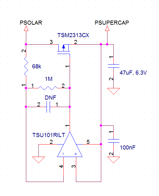
The attribution for that goes to "Perky" on the lowpowerlab forum.
-
This may be an improvement over the project schematic:
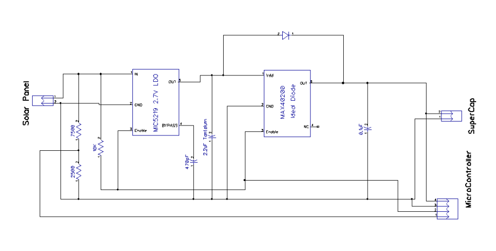
It uses an additional diode so that a nearly empty supercap can still be charged if the solar panel voltage is below the 1.5v minimum for the MAX40200 ideal diode. This needs to be tested, but the idea is that the MAX40200 would dominate once higher input voltages are reached. Anyway, the benefit of using an ideal diode in the first place is to avoid the very long charge tail that you get with a regular diode, but that isn't really a factor if the supercap is nearly empty. Hence, a hybrid approach may turn out to be optimal.
On the other hand, I expect most of the charging would happen at higher voltages anyway, so this is really just a refinement that may well be optional.
-
This may be an improvement over the project schematic:
It uses an additional diode so that a nearly empty supercap can still be charged if the solar panel voltage is below the 1.5v minimum for the MAX40200 ideal diode. This needs to be tested, but the idea is that the MAX40200 would dominate once higher input voltages are reached. Anyway, the benefit of using an ideal diode in the first place is to avoid the very long charge tail that you get with a regular diode, but that isn't really a factor if the supercap is nearly empty. Hence, a hybrid approach may turn out to be optimal.
On the other hand, I expect most of the charging would happen at higher voltages anyway, so this is really just a refinement that may well be optional.
OK, I tried it both with and without the diode, and the diode makes no difference. I think it's maybe because maybe the LDO (or its enable pin?) needs to see a minimum of 1v to pass any current at all, and more like 1.5v to pass current freely.
-
I updated and finalized the design files and BOM. I've also verified that it works. Project completed. :)
The main advantage of this design is the ability of the MCU to disable the Harvester enough to accurately read the voltage on the solar panel. If that doesn't matter to you, then my earlier solar charger project is simpler:
https://www.openhardware.io/view/382/Tiny-Solar-Charger-for-27v-Mote-Supercap -
OK, I tried it both with and without the diode, and the diode makes no difference. I think it's maybe because maybe the LDO (or its enable pin?) needs to see a minimum of 1v to pass any current at all, and more like 1.5v to pass current freely.
@neverdie said in 💬 Easy Supercap Fast Solar Harvester:
OK, I tried it both with and without the diode, and the diode makes no difference. I think it's maybe because maybe the LDO (or its enable pin?) needs to see a minimum of 1v to pass any current at all, and more like 1.5v to pass current freely.
You mean you made it only with the LDO ???
-
@neverdie said in 💬 Easy Supercap Fast Solar Harvester:
OK, I tried it both with and without the diode, and the diode makes no difference. I think it's maybe because maybe the LDO (or its enable pin?) needs to see a minimum of 1v to pass any current at all, and more like 1.5v to pass current freely.
You mean you made it only with the LDO ???
@nca78 No. I made one board that is what the project is. I made a second board that is what is shown in the schematic above, with the extra diode. The second board with the extra diode made no difference. Both boards contained the ideal diode.
-
@neverdie said in 💬 Easy Supercap Fast Solar Harvester:
OK, I tried it both with and without the diode, and the diode makes no difference. I think it's maybe because maybe the LDO (or its enable pin?) needs to see a minimum of 1v to pass any current at all, and more like 1.5v to pass current freely.
You mean you made it only with the LDO ???
@nca78 said in 💬 Easy Supercap Fast Solar Harvester:
You mean you made it only with the LDO ???
Here's a photo of the board I made and tested with the extra diode:
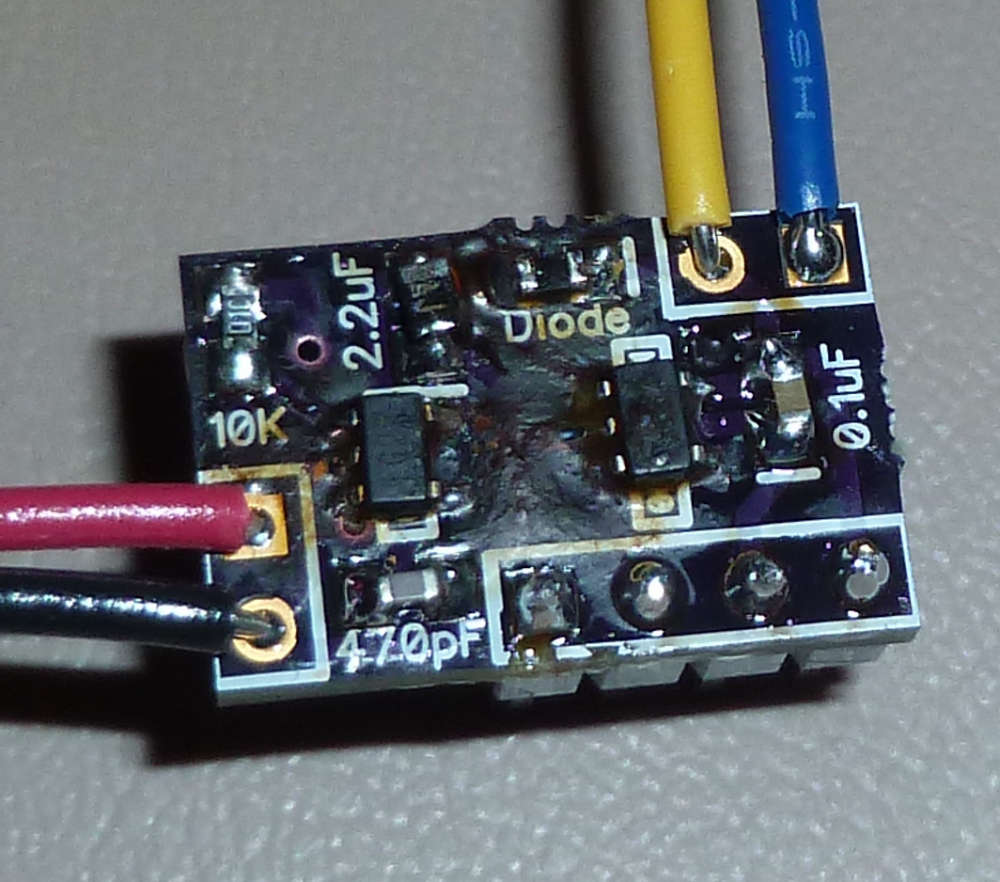
Hopefully that clears up any potential confusion.
-
Bad news I'm afraid. The enable/disable feature tested out correctly when powered by a bench power supply, but I found out today that when powered by a weak solar panel, it doesn't work as intended. DISABLE just doesn't provide enough of a full shut-off to accurately read the solar panel's voltage (the same voltage as if the solar panel were disconnected). Instead, a lower voltage is manifested.
Unfortunately, I don't know how to correct for this. Unless someone else can post a solution, I'm afraid this project probably is not worth doing. :(
Therefore, I am reverting it to "work in progress."
-
This isn't really harvesting, is it? Shouldn't be harvesting the collecting of even the lower voltages to be stored in the supercap?
-
OK, I changed the name, since two people have now commented upon it.
I have a new but totally different design sent off to fab which, while more elaborate, should allow proper voltage measurements of the solar panel by making it 100% completely unloaded for the duration of the measurement. I think in the end it will be cheaper to use some other sensor than the solar panel itself to get solar intensity measurements, but with this new design I'll be able to compare and then know for sure.
-
I'd consider harvesting anything that can store small quantities of energy and then convert them into usable energy. The other project you made with the booster being powered by a small cap is more hervester like
Why do you need to measure the solar intensity? -
Not sure yet, but, for example, it might be useful to know for managing energy expenditure if using smaller than supercap capacitors. You can get quite a lot of transmissions out of even a 100uF capacitor, but maybe it's better to simply queue the transmissions until the small cap is fully charged and the sun is shining brightly, so that the transmissions are "free", so to speak. With gobs of spare memory, a nRF52840 could store lots of detailed info which it only transmits under the right conditions. This might be especially true for very small devices with very tiny solar panels.
-
I am looking at schematic and I cannot understand why this does not work.
May be a low quality solar panel? What's wattage of the solar panel you tested?@alexsh1 It turns out it does work. You just need to substitute much higher value resistors (e.g. 10M instead of 10K and use much higher values for the resistors in the voltage divider) so that under low light conditions the voltage measured on the unloaded solar panel doesn't show less than it should.
-
@alexsh1 It turns out it does work. You just need to substitute much higher value resistors (e.g. 10M instead of 10K and use much higher values for the resistors in the voltage divider) so that under low light conditions the voltage measured on the unloaded solar panel doesn't show less than it should.
@neverdie That's good news. I am going to assemble one as I like the idea of disabling the harvester.
FYG - I am using this small board to read solar panel voltage and disable / enable voltage divider:
https://github.com/hallard/Battery-Voltage-Measure
works really well and simple enough.
Hello! It looks like you're interested in this conversation, but you don't have an account yet.
Getting fed up of having to scroll through the same posts each visit? When you register for an account, you'll always come back to exactly where you were before, and choose to be notified of new replies (either via email, or push notification). You'll also be able to save bookmarks and upvote posts to show your appreciation to other community members.
With your input, this post could be even better 💗
Register Login