💬 Supercap solar charger
-
-
That's an interesting take on "solar harvesting", I think I will test it.
Do you know of any equivalent to the max40200 ? It's not available for me
-
@nca78 said in
 Easy Supercap Solar Harvester:
That's an interesting take on "solar harvesting", I think I will test it.
Do you know of any equivalent to the max40200 ? It's not available for me
Stumbling across the max40200 was actually what motivated me to make this project, because it was both small and cheap. There are some others, but more expensive (around $3). and bigger. I could provide you with a link to that, or I could provide you with a schematic for making your own ideal diode using an opamp and some other discrete parts. Let me know if you want to pursue either one or both.
In terms of harvesting under low light conditions, I'm imagining that two 6v panels in series will be quite effective, but I haven't yet tried that, as I'm still waiting for the PCB to arrive from the fab.
-
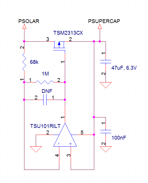
Here's a similar "ideal diode" circuit made from discretes, as I mentioned:

The attribution for that goes to "Perky" on the lowpowerlab forum.
-
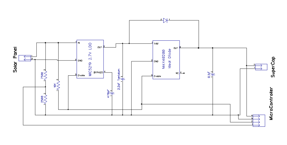
This may be an improvement over the project schematic:

It uses an additional diode so that a nearly empty supercap can still be charged if the solar panel voltage is below the 1.5v minimum for the MAX40200 ideal diode. This needs to be tested, but the idea is that the MAX40200 would dominate once higher input voltages are reached. Anyway, the benefit of using an ideal diode in the first place is to avoid the very long charge tail that you get with a regular diode, but that isn't really a factor if the supercap is nearly empty. Hence, a hybrid approach may turn out to be optimal.
On the other hand, I expect most of the charging would happen at higher voltages anyway, so this is really just a refinement that may well be optional.
-
OK, I tried it both with and without the diode, and the diode makes no difference. I think it's maybe because maybe the LDO (or its enable pin?) needs to see a minimum of 1v to pass any current at all, and more like 1.5v to pass current freely.
-
I updated and finalized the design files and BOM. I've also verified that it works. Project completed.

The main advantage of this design is the ability of the MCU to disable the Harvester enough to accurately read the voltage on the solar panel. If that doesn't matter to you, then my earlier solar charger project is simpler:
https://www.openhardware.io/view/382/Tiny-Solar-Charger-for-27v-Mote-Supercap
-
@neverdie said in
 Easy Supercap Fast Solar Harvester:
OK, I tried it both with and without the diode, and the diode makes no difference. I think it's maybe because maybe the LDO (or its enable pin?) needs to see a minimum of 1v to pass any current at all, and more like 1.5v to pass current freely.
You mean you made it only with the LDO ???
-
@nca78 No. I made one board that is what the project is. I made a second board that is what is shown in the schematic above, with the extra diode. The second board with the extra diode made no difference. Both boards contained the ideal diode.
-
@nca78 said in
 Easy Supercap Fast Solar Harvester:
You mean you made it only with the LDO ???
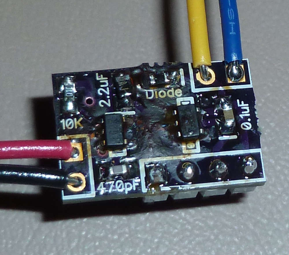
Here's a photo of the board I made and tested with the extra diode:

Hopefully that clears up any potential confusion.
-
Bad news I'm afraid. The enable/disable feature tested out correctly when powered by a bench power supply, but I found out today that when powered by a weak solar panel, it doesn't work as intended. DISABLE just doesn't provide enough of a full shut-off to accurately read the solar panel's voltage (the same voltage as if the solar panel were disconnected). Instead, a lower voltage is manifested.
Unfortunately, I don't know how to correct for this. Unless someone else can post a solution, I'm afraid this project probably is not worth doing.

Therefore, I am reverting it to "work in progress."
-
This isn't really harvesting, is it? Shouldn't be harvesting the collecting of even the lower voltages to be stored in the supercap?
-
@gohan How low does it need to be to qualify as harvesting?
-
OK, I changed the name, since two people have now commented upon it.
I have a new but totally different design sent off to fab which, while more elaborate, should allow proper voltage measurements of the solar panel by making it 100% completely unloaded for the duration of the measurement. I think in the end it will be cheaper to use some other sensor than the solar panel itself to get solar intensity measurements, but with this new design I'll be able to compare and then know for sure.
-
I'd consider harvesting anything that can store small quantities of energy and then convert them into usable energy. The other project you made with the booster being powered by a small cap is more hervester like
Why do you need to measure the solar intensity?
-
Not sure yet, but, for example, it might be useful to know for managing energy expenditure if using smaller than supercap capacitors. You can get quite a lot of transmissions out of even a 100uF capacitor, but maybe it's better to simply queue the transmissions until the small cap is fully charged and the sun is shining brightly, so that the transmissions are "free", so to speak. With gobs of spare memory, a nRF52840 could store lots of detailed info which it only transmits under the right conditions. This might be especially true for very small devices with very tiny solar panels.
-
I am looking at schematic and I cannot understand why this does not work.
May be a low quality solar panel? What's wattage of the solar panel you tested?
-
@alexsh1 It turns out it does work. You just need to substitute much higher value resistors (e.g. 10M instead of 10K and use much higher values for the resistors in the voltage divider) so that under low light conditions the voltage measured on the unloaded solar panel doesn't show less than it should.
-
@neverdie That's good news. I am going to assemble one as I like the idea of disabling the harvester.
FYG - I am using this small board to read solar panel voltage and disable / enable voltage divider:
https://github.com/hallard/Battery-Voltage-Measure
works really well and simple enough.
-
I must admit that the choice of the LDO is perfect.
I assembled one of these board and can use it with any solar panel up to 12V
-
Maybe the cleanest way to settle this would be to use an op-amp to buffer the voltage that's to be measured.
-
The LDO in the original BOM could handle input voltages up to 12v. I just now added an alternative LDO, which is pin compatible, to the BOM that can handle input voltages up to 30v.

-
A potentially simple solution would be to use very high megaohm values on the voltage-divider and to use a 0.1uF capacitor between GND and the sensing point on the voltage-divider. Evidence: https://jeelabs.org/2013/05/16/measuring-the-battery-without-draining-it/
Because of the very low current flowing through such a voltage-divider, the 0.1uF may require a small amount of time to charge (after the solar cell is isolated from the MCU by setting the EN pin low) before the atmega328p reads its voltage level.To summarize: Unlike the Jeelabs example, we're not worried about "draining" the solar cell, at least not in the sense that Jeelabs was trying to avoid a permanently connected voltage-divider from draining a battery. Rather, since in our case the goal is to read the open circuit voltage of the solar cell at a particular instant in time, our requirement is that the voltage flowing through the voltage divider be sufficiently minuscule that it does not skew the sampled voltage that we're trying to measure. Thus, one could imagine that under extremely low light conditions, where the solar cell may produce extremely little current, there might be a slight difference in the voltage measured on a voltage divider as compared with the voltage on a solar cell's true open circuit voltage. On the other hand, since both values would likely be approaching zero volts under such a worst-case scenario, perhaps it would be a wash, especially considering the 10-bit resolution of the atmega328p's ADC. Therefore, it seems worth a little testing to see whether this might be a viable solution.
-
@neverdie Do you know, I was just thinking about this scenario last night when I couldn't sleep.
Is there a reason a mosfet could not be added to the voltage divider (in series with it) and a pin on the arduino or whatever could turn it on for a reading and then off again for normal function?
-
@skywatch said in
 Supercap solar charger:
@neverdie Do you know, I was just thinking about this scenario last night when I couldn't sleep.
Is there a reason a mosfet could not be added to the voltage divider (in series with it) and a pin on the arduino or whatever could turn it on for a reading and then off again for normal function?
It could be done, but I can see only one benefit from doing so, which is that whatever current that would be lost/wasted by a permanently connected voltage divider could instead be captured as harvested energy. You would still need to solve the existing dilemma, which is finding a good technique to measure the open-circuit voltage of the solar cell without crashing the very voltage that one wishes to measure. Bear in mind that a small solar cell like that from an LED keychain may produce a net of only 8ua under normal indoor lighting conditions, and obviously only a fraction of that under more dim conditions. Below a certain dimness level the leakage currents inherent in the cell will likely exceed the current produced, resulting in zero current flowing even though some amount of light is still present.
I suppose a viable alternative might be to use a dedicated luminosity sensor of some kind, instead of forcing the solar cell to serve that purpose as well. The hope would be that, when calibrated, it could serve as a proxy for the solar cell and be used to gauge the amount of current and power being generated, which is what I'm most interested in anyway. On the other hand, different types of solar cells respond to different light wavelengths differently (as proven in the earlier discussion on the thread which this thread grew out of), so finding a luminosity sensor that responds in the same way as any particular solar cell might be difficult. i.e. it no doubt could be a proxy, but it might not be a good proxy, let alone an accurate one. I suppose some kind of spectroscopy would be the right kind of measuring tool, at least from a technical viewpoint. From a practical/economic viewpoint, maybe not so much, unless such sensors are both small and can be had at a reasonable price (and, purely as a wild guess, I'd wager they're probably neither small nor cheap).
-
Wow, I just now checked, and the price on spectrometers has really come down a lot! Something like this:
https://www.adafruit.com/product/3779
together with something similar for infrared might possibly be "good enough", provided that you worked out the conversion factors for the solar cell. Nonetheless... nearly $20 more than taking measurements from the solar cell directly.
It's the cheapest I've found so far. For something with better quality, the prices can be a lot more: e.g.
https://www.digikey.com/product-detail/en/seeed-technology-co-ltd/114991292/114991292-ND/7622897
-
I tested the Version 11 design, and it works. Therefore, I'm removing the "work in progress" moniker.
-
I'm just wondering should it be a single layer?
-
@Mishka It certainly "could" be. What makes you think that it "should" be?
-
@NeverDie It will be easier to produce it at home using a CNC router or etching.
-
@Mishka Ah yes, that is true. In this case though I went out of my way to keep the PCB dimensions as small as possible so that someone could have it made at OSH-PARK for super cheap--just $0.30 per board.
If I ever figure out how to post a complete set of KiCAD files, then I guess maybe then everyone can modify it to suit their circumstances. Until then, it will be hard to have one's cake and eat it too.