Looks nice in red
Posts made by emc2
-
RE: 💬 MySWeMosGWShield - WeMos Mini MySensors Gateway Shield
Looks like a neat module indeed.
Never tried these, but yes I guess if the external antenna and the wifi antenna are too close it may leat to some interferences.Would also need to check that the 3.3V is powerful enough to properly feed the esp and this chip at the same time, I guess it may depends on the antenna plugged to it too.
-
RE: 💬 MySWeMosGWShield - WeMos Mini MySensors Gateway Shield
@fabien Never heard of the "Ebyte NRF24 PA+LNA module", do you have a link for it somewhere?
So far I've been using a few of these with the "regular no name" PA+LNA from Aliexpress and did not have any problems. What are the symptoms you are observing?
-
RE: 💬 SMDnRF24_adapter
Forgot about this guy... Updated the project a little, the PCB now have footprints for both normal and PA+LNA modules.
The old boards are still available on the github repository if needed.Even with the extra length added to the PCB with the dual footprint, it is overall still smaller than a regular non SMD NRF24L01 module.
-
RE: 💬 MySWeMosIRShield - IR blaster shield for WeMos D1
Actually was not too bad to update.
I pushed the updated example sketch to github and openhardware, compatible with IRremoteESP8266 v2.0 and up.
I did a quick test here, no errors, and the vacuum cleaner already escaped to the bedroom, so good to go!As for the board, feel free to share any sketch here or on github.
-
RE: 💬 MySWeMosIRShield - IR blaster shield for WeMos D1
Short and not perfect answer, they changed everything when they updated the library to >2.0.
For a quick way to test your board etc, you can compile the example sketch by reverting to version 1.2.0
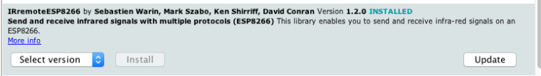
Ideally you may want to upgrade your sketch to be compatible with version 2.0 according to this https://github.com/markszabo/IRremoteESP8266/wiki/Upgrading-to-v2.0
I wanted to do it, but completely forgot about it... Will try to have a look at it tonight, but hopefully you can start testing everything using the old library version.
May also ask what minor modifications you did? Always open to suggestions to improve the board.
-
RE: 💬 MySWeMosGWShield - WeMos Mini MySensors Gateway Shield
@Mynasru unfortunately the only other suitable pin would be D1, SCL.
Wemos do not have enough pins to do gateway + I2C, you will need to switch to a nodeMCU or similar.Also keep in mind that D2 is a MySensor default for ESP8266, I tried to have it moved when support was added https://github.com/mysensors/MySensors/issues/408#issuecomment-191403862 but without success, meaning you will need to reassign CE in your code.
-
RE: NRF24L01 SMD to DIP converter
@bilbolodz Actually a PA+LNA version is on github (untested)
https://github.com/emc2cube/SMDnRF24_adapter/tree/master/PA_LNABut yes, I did not update the openhardware part yet.
-
RE: 💬 MySGrowLED - MySensors control for Grow Lights or Greenhouse
The choice of MOSFET can be tricky. Seems that irlz44n was discontinued so you may need to find one adapted to the voltage and current you want to handle.
In all the cases you need to get a logic MOSFET too, meaning that they are fully open usually around 1 to 3V.Also I'm sort of confused as it seems to me that L7812CV is a Voltage regulator, not a MOSFET. So if you are actually using that in the MOSFET spot it will definitively not work.
Especially if you are handling high current or voltage I would recommend using one from a reputable source for your MOSFET, I recently switched from mouser / digikey / aliexpress to mostly use http://www.arrow.com as you get free regular shipping, event if you order a couple of components (no affiliation to them whatsoever).
-
RE: 💬 MySRaspiGW - MySensors Raspberry Pi GPIO Gateway
@reinhold I bet it's an IRQ issue:
If you are using version 1.1 of the board, with IRQ support, you need to compile the software on the pi with the --my-rf24-irq-pin=18 option (see Install section on openhardware / github)
By default IRQ is on pin 15 so my bet is that if it's working by following https://www.mysensors.org/build/raspberry you just need to recompile the software with this option and it should work
-
RE: 💬 HALO : ESP32 multi transport GW/Bridge for Mysensors
@scalz said in
HALO : ESP32 multi transport GW/Bridge for Mysensors:
So far (but not digged a lot) i've only seen PA smd modules with ipex (but would be better if i could fit sma) or chip antenna (lol). Are you thinking to an other reference, or have a favorite module??
This work quite well with the IPX PA+LNA SMD modules
-
RE: MySensors Contest 2017 - Winners
Congratulations to everyone, and a big thanks to PCBWay!
-
RE: 💬 MySWeMosIRShield - IR blaster shield for WeMos D1
@Nca78 Not sure either to be honest, but technically I only did the calculation for a specific type of LED, the ones in the BOM.
I do use TSAL LEDs, and used http://ledcalc.com/#calc to do the resistor calculation for 7 LEDs with numbers extracted from the datasheet, leading to the ~5ohm resistor calculation.
I tried without any, or with a 4.7ohm resistor and I had significant better range results without resistor. Not a surprise, looking at the IR signal with a smartphone camera you can definitively see a brightness difference too, that's really a blasterNo burned LED after 48h of testing (sending one of my IR code every 5s). I also tried, for 10min, with regular red LED (http://www.nteinc.com/specs/3000to3099/pdf/nte3019.pdf) which have lower Vf and If requirements, no problems either.
I don't say that this is right, I truly don't have the background to do more than empirical experimentations, but it seemed good enough for me at the time. I did not had any problems since then, both with real TSAL from mouser and probably fake ones from aliexpress.
-
RE: 💬 MySWeMosIRShield - IR blaster shield for WeMos D1
I hope you will like this board when you receive it!
True, no current limiting resistor in that configuration for IR LEDs. One of my previous version had one and IR signal was quite dim. By having 7 LEDs the current in each one is actually quite low, and they are only ON for a few micro seconds. I have been using this specific configuration for 3 months now (breadboard to various prototypes) and no burned LEDs so far.
It may differ for other IR LEDs, but TSAL series is pretty resilient and by using 7 LEDs it can take up a few amps without any problem. (If you do the calculations you will find that you could add a 5ohm resistor to limit to 100mA, or 2.5ohm for 200mA, so as you can see it's safe to skip)
Even using ONE regular (visible light) LED for a quick test to send a signal is actually ok, but leaving it on for more than 5s is sufficient to burn it. Having all seven LEDs, they were still working after 1 minute being ON, which is already far from any real case use.
-
RE: 💬 MySWeMosIRShield - IR blaster shield for WeMos D1
Thanks @hek , yes I did saw it. I did try to port it to work on ESP8266 with IRremoteESP8266.h but without success so far.
That's totally why my first point is "be able to record, save and reuse an IR code without editing the code. Plenty of EEPROM space to store data", which is what this sketch was able to do. I have the feeling that someone that know what he is doing can probably do it easily, but for me it's a nightmare.
-
RE: 💬 MySWeMosIRShield - IR blaster shield for WeMos D1
Arduino sketch is really basic and even if it works perfectly for me, there is probably a way to improve it greatly.
On top of my head it would be good to
- be able to record, save and reuse an IR code without editing the code. Plenty of EEPROM space to store data.
- have a webpage showing the serial console to see received IR codes, or other info.
- have a dynamic webpage automatically displaying all codes stored in such EEPROM.
- have more than 10 codes that can be used with domoticz.
But I do not know how to do this (even if it's possible).
If you are interested in improving this code shoot me a private message, or answer here. I have a few extra PCBs from a previous version that I will gladly send for free to anyone willing to improve this device software. -
RE: BME280 temp/humidity/pressure sensor
Was modified in 2.1.1, you need to change
metric = getConfig().isMetric;
to
metric = getControllerConfig().isMetric; // was getConfig().isMetric; before MySensors v2.1.1
-
RE: 💬 MySWeMosGWShield - WeMos Mini MySensors Gateway Shield
Glad to see you have it working!
Let me know if something was unclear in the instructions or if it can be improved to prevent people to solder them flipped.
-
RE: NRF24L01-PA-LNA in components library wrong?
Ah yes right.
For non-smd they both have the same pinout, so you should be able to design it using the regular footprint, and then just plug a PA+LNA module in the header. -
RE: 💬 MySWeMosGWShield - WeMos Mini MySensors Gateway Shield
Not sure. I do not have any RFM sensors, I tested the gateway for a little more than a week with a mock sensor and it was working. Maybe some logs could help?
You can also hook up the RFM shield to a regular arduino nano to do a serial gateway, this way you can check if it's radio dependent or not.
-
RE: NRF24L01-PA-LNA in components library wrong?
@LastSamurai Originally I designed it but since then it has been added to the official mysensors-kicad repo https://github.com/mysensors-kicad
Both regular SMD and PA+LNA SMD footprints and 3d shapes are verified to be working, I already used them quite a lot. -
RE: NRF24L01-PA-LNA in components library wrong?
Also the case of the footprint in the library.
-
RE: 💬 MySWeMosGWShield - WeMos Mini MySensors Gateway Shield
It should indeed "beep" between all the pins.
NRF modules are also very fragile, once incorrectly plugged they are usually definitively toasted. So even if you desoldered and then resoldered them correctly it is unlikely they will work correctly.
Yes you need the capacitor radio side, it's the only required component, everything else is optional. It don't have to be 4.7µF, anything between 4.7 and 47µF will do, as stated in the assembly instructions.
-
RE: 💬 MySWeMosGWShield - WeMos Mini MySensors Gateway Shield
It should not get hot at all. The Wemos can get a few °C above room temperature but definitively not "hot as hell"
It happened to me once, when I had some solder joints between 2 pins of the NRF. You may want to test with a multimeter if, when the WeMos is unplugged, you have any shorts between adjacent pins.
A picture of the soldered board may help too.Best way is to edit the example sketch by adding your Wifi credentials on it before uploading them.
-
RE: 💬 MySRaspiGW PA+LNA - MySensors Raspberry Pi GPIO Gateway
@EddyG PCB received and tested, new version (v1.1) available here and on github.
-
RE: Getting more usable input pins on Wemos D1 Mini / ESP8266
@mfalkvidd right, I was thinking of updating RFM69 wiring diagrams on https://www.mysensors.org/view/171#rfm69-&-esp8266 , but for how the radio module go I was interested in the rfm96 range / reliability to see how it goes.
Anyway I will look for futures updates on the forum.
-
RE: Getting more usable input pins on Wemos D1 Mini / ESP8266
I'm interested to see how it goes and how a GPS module can be used.
As for the official wiring diagram, eventually consider using D2 as the default IRQ pin on it, this way it's consistent with nRF24 wiring (and can even reuse the same picture), and many people used it this way mostly since this https://forum.mysensors.org/topic/3061/solved-esp8266-gateway-with-rfm69-wdt-issues/4 post.
-
RE: Getting more usable input pins on Wemos D1 Mini / ESP8266
Yes if it's already there no need to redefine it, seems it's only missing when in gateway mode.It may be a RFM96 issue then, if you have a RFM69 lying around you may want to try if it works with it, I had it working and some others too with NSS on D8 and IRQ on D2, so something may behave differently.Guess we posted at the same time, good to see it's working for you too.
-
RE: Getting more usable input pins on Wemos D1 Mini / ESP8266
@mfalkvidd
Just to try, if not present, do you mind adding to you sketch#define ARDUINO_ARCH_ESP8266
-
RE: Getting more usable input pins on Wemos D1 Mini / ESP8266
Yes I only needed #define MY_RF69_SPI_CS D8
Glad to see it worked for you!
I did not pay attention that we had an official wiring esp8266 / RFM yet, but It seems there is actually a mistake on the website, the table says NSS -> D2 but on the schematic it's using D8. Maybe D8 is default and you had some issues on that if you were using D2 without #define MY_RF69_SPI_CS D2 ?
I'm personally using D2 for IRQ so maybe by switching things around you can get even more usable pins!
-
RE: Getting more usable input pins on Wemos D1 Mini / ESP8266
Not really sure how you need / have wired everything together so it may not be relevant but:
- Can you use TX and RX to wire your GPS module, maybe using MY_DISABLED_SERIAL
- On a RFM69 (and D1 pro mini) I can use D8 for CSN/NSS without any problems
- D0 should be totally fine to use I had no problem using it for various functions on my side (but never tried with a GPS module)
-
RE: ESP8266 and RFM69 send issue
I had the same problem when I was troubleshooting RFM69 on my Wemos GW shield.
It seems to me that
#define MY_RF69_IRQ_NUM MY_RF69_IRQ_PIN
Is supposed to be automatically set when
#define ARDUINO_ARCH_ESP8266
is defined.
You would assume that when you define
#define MY_GATEWAY_ESP8266
It would automatically add
#define ARDUINO_ARCH_ESP8266
For example here in MySensors.h but it is not, meaning that
#define MY_RF69_IRQ_NUM MY_RF69_IRQ_PIN
is never declared.
So you can simply use
#define ARDUINO_ARCH_ESP8266 #define MY_RF69_IRQ_PIN D1
or
#define MY_RF69_IRQ_PIN D1 #define MY_RF69_IRQ_NUM MY_RF69_IRQ_PIN
in your sketch.
I personally think it should be automatically done in MySensors.h (and would be happy to submit a ticket on github if needed) but maybe it was done on purpose.
-
RE: 💬 MySRaspiGW PA+LNA - MySensors Raspberry Pi GPIO Gateway
I ordered some PCBs (IRQ on pin 18 only) yesterday night, should be there in ~2weeks to test.
I tend to hide the Pi in a corner so I don't really care for additional LEDs personally.
Without --my-rf24-pa-level=RF24_PA_LOW you should still be able to receive any signal, on an old version 1 model B you can't send anything, not enough power, but it seems that for most people it works on a Pi 3B and 2B+.
-
RE: 💬 MySRaspiGW PA+LNA - MySensors Raspberry Pi GPIO Gateway
True quite a shame. I was planning to create a cleaner PCB with eventually LEDs and RFM69 when supported and forgot it in a corner.
I actually already have a IRQ design ready (only IRQ added, no LEDs, not sure how often LEDs are used), I will try to order it this week and test it soon after.
If you want to try it on your side before any official release just PM me.
On recent Raspi3 it should work without --my-rf24-pa-level=RF24_PA_LOW give it a try if you have the opportunity to do so.
-
RE: Ultra low temperature (-80ºC) monitoring probes
@sbpurohit I assume it comes with everything (else it would defeat the point of the kit), but I would suggest you to email PCBway to have direct confirmation with them.
-
RE: Ultra low temperature (-80ºC) monitoring probes
No I do not sell these assembled.
I think the only option on openhardware is DIY kit, but with the included Gerber files and BOM you should be able to have it assembled at a local fab house.For notifications, mine is actually linked to IFTTT using a script in domoticz, but basically you can use any notification functions used in your controller.
-
RE: 💬 MySWeMosGWShield - WeMos Mini MySensors Gateway Shield
@gloob Did you had time to test on your side and can confirm that everything is working correctly?
-
RE: 💬 Advanced Gateway Options
@maghac said in
Advanced Gateway Options:
However, they are always on, and only blink off when receiving or transmitting. Is this intended? Can it be inverted (so they are off normally but only on when there is activity).
You should be able to use#define MY_WITH_LEDS_BLINKING_INVERSE
But because of the weird wiring on esp8266 based boards it's always a hit or miss, some LEDs should be inversed, some other not. You may have to play with pull-ups or pull-downs resistors on some pins.
-
RE: How to scan rf remote
Install the library "rc-switch" by sul-77 in Arduino (it can be installed with the library manager)
Upload one of the ReceiveDemo sketch to your Arduino (and wire a 433MHz receiver accordingly) and it will show you the RF codes, that you can then emulate by plugging a 433MHz Tx (see SendDemo sketch for code example)
-
RE: 💬 MySWeMosGWShield - WeMos Mini MySensors Gateway Shield
I think I did.
Could you test by making sure you add / have the following lines in your sketch:#define MY_RF69_IRQ_PIN D2 // GPIO 4 #define MY_RF69_IRQ_NUM D2 // GPIO 4 #define MY_RF69_SPI_CS D8 // GPIO 15
It seems that the automatic definition of MY_RF69_IRQ_NUM was not working properly (I think on esp8266 platform it was supposed to be automatically defined as equal to MY_RF69_IRQ_PIN but I guess it was not the case)
Right now I have it working, both gateway and sensor compiled with MySensors 2.1.1.
I updated the default sketch, adding the missing line, and it's now available on github.
Let me know how it goes for you.
-
RE: new RFM69 Gateway and node
Good to know.
I guess this is not a MySensors weather station, do you mind sharing the code you used, or project (I found a few on github).
I will have a look in the code to see if there is something obvious somewhere. -
RE: No RFM69 - No error
Thanks!
Will have a shot at it tonight to try to troubleshoot this. -
RE: new RFM69 Gateway and node
@gloob I received my RFM69 radio modules yesterday and did a quick test.
Same as for you, I'm unable to have a "MockSensor" talk to an esp8266 based gateway, both WeMos or NodeMCU.Never used RFM69 before so I'm not sure how to go from there, will do a few more tests on evenings and this week end, let me know if you got something on your side.
-
RE: No RFM69 - No error
@tekka Is there a branch somewhere with this refactored driver to test?
Seems there is something acting strange with RFM69 + esp8266 -
RE: rewards for sharing
Thanks Jonathan,
I guess I was mislead and thought we were also able to get solder paste even for blank PCBs. My bad!Any interest to see with @hek if it would be possible for you to join openhardware.io as a manufacturer?
-
RE: 💬 MySWeMosGWShield - WeMos Mini MySensors Gateway Shield
I answered to your other topic, but I think that's because you are not defining the IRQ and CS pins in your sketch.
Have a try by using the provided sketch on the Gateway, or define the pins on yours, it should hopefully fix your problem.
-
RE: new RFM69 Gateway and node
One thing seems to be missing for your GW sketch.
In the example sketch I provide I define some things that seems to be missing here:#define MY_RF69_IRQ_PIN D2 // GPIO 4 #define MY_RF69_SPI_CS D8 // GPIO 15
Could you try with the included "MySWemosGatewayESP8266OTA.ino" sketch to see if this one is working?
-
RE: 💬 MySWeMosGWShield - WeMos Mini MySensors Gateway Shield
Yes and no.
I tried with a RFM69 and I did not got any errors / complains on the serial log, but I do not have any other RFM devices to test with (still waiting for radio modules, probably lost again...)
-
RE: 💬 MySI2CNode - Node for I2C devices, CR123 or USB powered
I see a lot of "!TSF" and "NACK" which seems to be radio communication problems.
That's MySensors related and can be related to many things, from soldering problem to power / capacitor issues.In MY_DEBUG mode you should see your temp/hum printed on serial every ~15s so there is something wrong there, either wiring or a code issue.
Ty with the example included with the library "i2c_SI7021.h", without any MySensors related stuff, to see if your sensor is detected. You should see temp/hum on the serial.
-
RE: rewards for sharing
No idea. I would assume it can be packed in a way to prevent this (vacuum sealed maybe?)
You can always email them to have more infos. -
RE: 💬 MySI2CNode - Node for I2C devices, CR123 or USB powered
Soldering the radio is the tricky part if you are using it with a battery holder as you need to solder it last. A fine tip on the soldering iron is a must.
Before powering up, I would recommend using a multimeter in continuity mode and check every radio solder pads. Pads next to each other should not be in contact. You can also trace back each pad back to their respective arduino pin and see if you have continuity there.For temp/hum data it could be because of many things:
- First, did you add a temp/hum sensor? This PCB is designed to add I2C sensors but by itself do not have any.
- If you did, which one did you add? Provided example sketch is for si7021 based sensors such as https://www.aliexpress.com/item/Industrial-High-Precision-Si7021-Humidity-Sensor-with-I2C-Interface-for-Arduino/32524005324.html or https://www.aliexpress.com/item/Humidity-Sensor-with-I2C-Interface-Si7021-for-Arduino-Industrial-High-Precision/32687207471.html These two should work out of the box with the included sketch.
- Is your sensor working on an arduino without MySensors? You may need to adapt the code to your specific sensor (different I2C address maybe?).
-
RE: 💬 MySI2CNode - Node for I2C devices, CR123 or USB powered
My bad, please replace
const unsigned long SLEEP_TIME = 1800000UL; // Sleep time between reads (in milliseconds) #if defined MY_DEBUG SLEEP_TIME = 15000UL; // If debug, TX every 15s #endif
by
#if defined MY_DEBUG const unsigned long SLEEP_TIME = 15000UL; // If debug, TX every 15s #else const unsigned long SLEEP_TIME = 1800000UL; // Sleep time between reads (in milliseconds), 30min #endif
Corrected code will be uploaded in a few minutes.
Thanks!
-
RE: rewards for sharing
Never tried on my own yet.
No additional cost.
You need to provide a gerber file for the paste of course and it needs to follow these specifications https://support.pcb.ng/support/solutions/articles/9000057010-pcb-constraints#paste -
RE: 💬 MySGrowLED - MySensors control for Grow Lights or Greenhouse
Glad it's working for the radio part.
If you don't hardcode the node ID it's always a good thing to use the "Clear Eeprom" MySensors sketch to be sure your arduino did not keep a former ID, else you end up with duplicates.For 1-wire you can also check them using the "MySGrowPCB_test.ino" sketch, serial log will try to detect everything.
-
RE: 💬 MySGrowLED - MySensors control for Grow Lights or Greenhouse
Hi Dave.
You should only need to change what is in the "configuration" part of the sketch.
- Optionally change String Location = "Plants"; to something more meaningful
- Enable/disable the "modules" LED, FAN and various sensors depending on what you soldered on the board
- Optionally setup the radio settings for your network.
Assuming, as you seem new with this system, that you only have these devices I would not change anything on the radio part and leave everything commented out like this:
//#define MY_NODE_ID 42 //#define MY_PARENT_NODE_ID 0 //#define MY_REPEATER_FEATURE
You probably don't need to edit #define SN "MySGrowLED", but can it's fine.
Then for your problem I can see 2 possibilities:
- You manually defined a node ID for your board and both have the same, ex:
#define MY_NODE_ID 42
I would recommend to leave it disabled so domoticz take care of it itself.
- Something wrong in the wiring.
If the node ID was setup correctly can you post here the "configuration" part of both of your arduinos?
Ideally a screenshot of your domoticz devices and switch may help to check they have individual IDs assigned.
Finally a picture or schematic of your whole setup including how each modules is wired to each LED driver / fan may help too.I currently have 3 modules running, and except a different name and manual node ID I did not change anything else between them so it should work for you too.
-
RE: rewards for sharing
My order was placed on November 3rd and it was shipped on the 16th (9 business days, 13 "real" days).
Don't forget they give you an average and it's probably in business days, as you ordered just before christmas it's been probably only ~2-3 business days so far.
-
RE: IR Blaster (progress)
@scalz said:
@emc2 hehe. i don't think this is overkill
depends on what features. well let's see how it will work. mine is already designed but i won't have lot of time before beginning of the year now
Agreed, depends on the features, in my case I did not really think of any additional features, just IR stuff. PCB was designed yesterday, I will play with a protoboard to check if everything works and then will see how to improve everything before ordering.
-
RE: 💬 MySWeMosGWShield - WeMos Mini MySensors Gateway Shield
@Nca78 said:
Too bad my NRF orders (standard SMD and pa/lna SMD) have both disappeared the same day 2 months ago just after they passed the Chinese customs
I had the same problem with my order of RFM modules and push buttons, took forever to be able to assemble everything for testing and taking pictures. I guess 2 months ago they were sending a lot of stuff out to be ready for Christmas in stores.
@NeverDie said:
I like how you included many different radio module options onto a single shield and that the shields are stackable, so that you can "have it all" on one gateway if you wish.
I may be wrong, or did not understand you correctly, but I don't think you can "have it all" on a single gateway. You can have 4 different gateway if you want (3xRFM69 with different frequencies + NRF24) but you can't stack different radios on the same arduino/esp. But yes definitively a way to use the extra boards you get from the fab house. You can also use the WeMos as a node/repeater and ignore/disable WiFi or even better add a WiFi layer to do something else (direct http api, remote serial monitoring, webpage to update firmware, etc...). I don't really know how to do that, but I'm sure some smart people do. On a WeMos you don't have a lot of pins left when the radio is plugged, but it should be enough for many projects.
How well do the YJ-13039 modules (i.e. the amplified, high-powered version of the NRF24L01+ SMD module with the chip antenna) work? Prior to your post, I didn't know that a surface mount module of that kind even existed. It sounds quite promising! How does its range compare to the rfm69 as well as to the reglar NRF24L01+?
These PA+LNA SMD module work nicely. I have one of these on my current GW https://www.openhardware.io/view/116/MySRaspiGW-PALNA and so far no complaints. I really like these NRF SMD modules (regular and PA) as they fit under a pro-mini between its headers. It allows you to have a very compact device when assembled.
Range wise, no idea. A regular NRF is already enough to cover my whole (small) apartment with cardboard walls (they don't really know what insulation is in California...). Until 2 days ago I never had / tested a RFM radio so no idea either. But maybe someone else did some tests with these modules? Else if you do let me know how it goes.
-
RE: 💬 MySWeMosGWShield - WeMos Mini MySensors Gateway Shield
Yes, everything worked fine with a PA+LNA module or a RFM69HW using the WeMos 3.3V output.
I only tested on a D1 mini pro, but the D1 mini V2 use the same RT9013 (3.3V, 500mA) regulator so should not matter. -
RE: IR Blaster (progress)
@scalz Cool! Let me know when you have some details on that. I may stick to esp8266, esp32 seems to be overkill for what I'm thinking, but if you have any tips let me know.
@blacey I saw this request, I can see the use of it, will see if I end up with a spot for one. One thing still, are these standard in term of where is ground and where is VCC on the mono 3.5mm jack? (I assume GND is "outside" and VCC is the "tip" but I may be wrong)
-
RE: Gateway on OSH Park
@gloob
Yes, see https://www.openhardware.io/view/303/MySWeMosGWShieldI have now received the RFM69 modules and seems to work (at least nothing wrong in the debug log, I don't have any RFM69 node to test yet).
@hek could you merge this to https://forum.mysensors.org/topic/5580/myswemosgwshield to regroup all discussions on only one forum thread? Thanks!
-
RE: IR Blaster (progress)
@blacey @scalz
I'm thinking of starting to do an IR blaster on my own, any chance to get a glimpse of what you are cooking on your side to either wait / see what kind of function you plan?On my side I'm thinking of:
- Eventually esp8266 based (probably using a WeMos mini Pro) to allow a wide range of usage even out of MySensors.
- Micro usb powered (using the WeMos' port)
- SMD nrf24L01, eventually RFM too if it fits on the PCB.
- optional ATSHA.
- IR leds on the side (roundish PCB?)
- Optional IR receiver
-
RE: rewards for sharing
@NeverDie said:
That pcb.ng sounds very interesting if they'll actually send you a fully assembled PCB in just 12 days, which is what they appear to be offering. With many parts being so incredibly tiny (e.g. BQ25504 and others) these days, I really hate the soldering part. Did you get a fully assembled board from them, and if so, how did it go? If it truly is affordable, I'm definitely interested.
No I got a PCB only, it was for https://www.openhardware.io/view/296/MySFreezer (you can see the PCB color, it's a nice burgundy / cardinal red which actually was the perfect fit for my workplace freezers), not a lot of component on it and depending the use actually not a lot are needed in the same time, and definitively not designed to be automatically assembled for the battery configuration.
One interesting thing on pcb.ng is the fact if you submit a solder paste layer they will actually add the paste, so you can reflow it yourself with a pan in your kitchen (dirty but works).
Assembled price is $8 / $12 per sq. in. (single / double sided assembly) + components I guess. With tiny components and a dense layout it could totally be worth it.
@hek Jonathan (https://blog.pcb.ng/author/jonathan-hirschman/) is quite nice and responsive, you can always shoot him an email to see if he is interested.
-
RE: rewards for sharing
I used them (and http://pcb.ng but unfortunately they don't have a way to easily share boards) and I was quite happy with the resulting PCB.
-
RE: Ultra low temperature (-80ºC) monitoring probes
In case someone ends up on this topic using the search function, PCB and code for using a 4-20mA sensor is available on https://forum.mysensors.org/topic/5508/mysfreezer
-
RE: Gateway on OSH Park
Yes you can skip everything except C1 (you can use any 4.7-47µF here) and the radio module.
If you have them around adding C2 and C3 is always a nice touch as it will remove some extra noise from the power supply but they are not required.
Even the voltage regulator should not be needed, but if you are using a PA+LNA or RFM69HW and have some Tx issues adding it should fix it, but at least on the WeMos D1 mini Pro the 3.3V regulator seems powerful enough in my tests.
-
RE: Gateway on OSH Park
Depends.
It was tested (and works) with NRF24L01 radios, but I'm still waiting for my RFM69 modules to show up to test these.On top of OSH they are also on PCBs.io, if you prefer black to purple.
See my github repo for more infos, it will also be on openhardware when fully tested etc.
-
RE: 💬 Atmospheric Pressure Sensor
BME280 is quite nice. I got one last year that I added to my gateway and it worked flawlessly since then.
If you remove the gateway/esp8266 top part you should be able to directly use code from https://github.com/emc2cube/MyWeatherGatewayESP8266 (which was updated from this one anyway)
-
RE: Nodemcu + RFM69. Level converter needed?
It seems good on the gateway to me, no radio error at least.
Past that no idea. -
RE: Nodemcu + RFM69. Level converter needed?
I guess you would need to give the logs for the gateway too, to see if you have a radio fail somewhere.
-
RE: Nodemcu + RFM69. Level converter needed?
And you set up the pins radio type in your gateway sketch too right?
// Enables and select radio type (if attached) #define MY_RADIO_RFM69 #define MY_RFM69_FREQUENCY RF69_868MHZ #define MY_RF69_IRQ_PIN 4 #define MY_RF69_SPI_CS 15
-
RE: 💬 Building a WiFi Gateway using ESP8266
I'm currently adding some wifi gateways at work, I was wondering:
- is ATSHA204 signing support something planned, or will it stay on soft-sign only mode?
- is IRQ support something planned too?
It's mostly to see if I need to plan to add these features on the PCB for later, or not.
Thanks!
-
RE: 💬 FOTA (Wireless Programming)
It may be a silly question, but what is the point of setting the fuses before burning the bootloader (using Dualoptiboot)?
After burning the bootloader fuses are changed to E:06, H:D2, L:E2 anyway as set in board.txt
MysensorsMicro.bootloader.unlock_bits=0x3F MysensorsMicro.bootloader.lock_bits=0x0F MysensorsMicro.bootloader.low_fuses=0xE2 MysensorsMicro.bootloader.high_fuses=0xD2 MysensorsMicro.bootloader.extended_fuses=0x06
Should we burn them after to revert to E:06, H:DA, L:E2 ? (and loosing EESAVE which seems bad)
-
RE: Esp8266 with wifi off
Make sure you include this in your sketch
#include <ESP8266WiFi.h>
Then add the following lines at the beginning of your setup()
WiFi.disconnect(); WiFi.mode(WIFI_OFF); WiFi.forceSleepBegin(); delay(1);
It should totally disable ESP WiFi functions and basically you end up with an arduino nano.
-
RE: MySensors + NRF24L01 + RasPi2?
@ikkeT said:
It's a bit shame that in many of the pinout descriptions it's not mentioned clearly which version of raspi pinout it is.
Unless you have one the few revision 1 of the Pi B (256MB model) all Pi have the same pinout for their GPIO. Even if you have a 256MB rev1 Pi B, for MySensors wiring this is actually the same. Maybe one of your wire was simply plugged incorrectly the first time?
-
RE: MySensors Raspberry port suggestions
@marceloaqno Up to you. I don't mind giving it a shot, if I send you the pcb alone it will fit in a regular letter and should not even have to go through customs etc. Worst case scenario it won't reach you.
-
RE: MySensors Raspberry port suggestions
@marceloaqno Thanks for the heads up.
I'm totally happy with the ethernet version, but as it seems @hek is in the process of writing guides on https://www.mysensors.org/build/raspberry I did a few tests.If I understood correctly (and it seems to work), to "replace" the 1.x serial gateway with the new one running the following command should work as is (/dev/ttyUSBMySensorsGateway can be renamed to /dev/ttyMySensorsGateway to be exactly as in 1.x or /dev/ttyUSB20 to bypass the symlink step)
./configure --my-gateway=serial --my-serial-is-pty --my-serial-pty=/dev/ttyUSBMySensorsGateway --my-rf24-pa-level=RF24_PA_LOW
--my-rf24-pa-level=RF24_PA_LOW can be omitted, especially if not using a PA+LNA module, but it seems 2.0 is really more power hungry than 1.4.
@marceloaqno said:
Those are cool adapters, I need to build one for me.
If you are interested by the SMD ones, PM me your address and I will happily send you something!
-
RE: MySensors Raspberry port suggestions
Same, I had one Pi with GertSanders adapter and now switched to the SMD versions to fit nicely in my case.
https://www.openhardware.io/view/105/MySRaspiGW
https://www.openhardware.io/view/116/MySRaspiGW-PALNAInterestingly the regular one is working better than the PA+LNA version since moved to 2.0, at least in term of sending commands. Receiving is fine. Compiling with --my-rf24-pa-level=RF24_PA_LOW helps a lot. It seems 2.0 is really more power hungry, any hope to optimize this?
Which remind me of one thing, sorry to bother you again @marceloaqno (how) is the --my-rf24-irq-pin=<PIN> working?
I installed wiringpi to get rid of the wiringPiISR: Can't find gpio program but I'm not sure if it's supposed to do anything in the long term.
I was thinking updating the design of my PCB to link BCM 24 (pin 18) to the IRQ pin of the radio module but it's unclear to me if the IRQ will ever actually be used on the gateway. -
RE: MySensors Raspberry port suggestions
@alexsh1 said:
I can confirm that the Ethernet GW works fine without --my-controller-ip-addressJust a guess, I see on your previous post that you used --my-controller-ip-address=127,0,0,1 it may have been a typo here, but did you try with --my-controller-ip-address=127.0.0.1? (dots instead of commas in the IP)?
-
RE: MySensors Raspberry port suggestions
@alexsh1 said:
For whatever reason Domoticz did not see ttyMySensorsGateway so I had to create ttyUSB20
Domoticz seems to only look for ttyUSB* interfaces. One easy trick is to run ./configure with this option so you don't have to worry with symlinking
./configure --my-serial-pty=/dev/ttyUSBMySensorsGateway
BTW @marceloaqno , what does the option --my-serial-is-pty exactly do?
So far I've been running the gateway in ethernet mode for a little while and it's working flawlessly, thanks a lot for this port. -
RE: MySensors Raspberry port suggestions
So I did a few tests, one of my setup is working on the last commit, the other not. Both are model B.
-
Working Pi:
Domoticz image, upgraded and up to date wheezy -
Commit 7d51087e589afb1296e71442fe2164807da399ef Pi:
Regular (non-Domoticz) old wheezy image updated to jessie
All are up to date for all package on apt and firmware is up to date for rpi-update
Linux domoticz 4.4.15+ #897 Tue Jul 12 18:38:58 BST 2016 armv6l GNU/Linux
My bet is that my "non-working" Pi, wich is also my guinea pig Pi, is missing a dependency or something. Let me know if I can get you some logs to troubleshoot, but it may be very specific to this setup so may not be worthwhile investigation unless a common factor start to emerge.
Anyways, thanks for the port!
-
-
RE: MySensors & RPi?
@jerseyguy1996 Well yes and no.
My radio is connected as explained in https://forum.mysensors.org/topic/2437/step-by-step-procedure-to-connect-the-nrf24l01-to-the-gpio-pins-and-use-the-raspberry-as-a-serial-gateway
Radio is detected, but it does not appear as a "serial" by that I mean it's not showing as "/dev/tty*" you have to set it up as as Ethernet gateway, with the IP being your Pi. -
RE: MySensors & RPi?
@jerseyguy1996 almost.
There is a working version of PiGateway on https://github.com/marceloaqno/MySensors/archive/7d51087e589afb1296e71442fe2164807da399ef.zip thanks to @marceloaqnoThe last commits do not seem to work for me, but it may be a problem on my side.
PiGateway create a gateway that can be accessed on the network, so on your controller choose 127.0.0.1 port 5003 and it works!
Only drawbacks for now:
- You have to add your devices again
- No proper init script, either launch it manually or add a cron task at boot
-
RE: MySensors Raspberry port suggestions
That's great, thanks @marceloaqno
I just started testing but I had to revert to 7d51087e589afb1296e71442fe2164807da399ef to have it working.
Last commit SEGFAULT afterEth: Listening for connections on 0.0.0.0:5003
Also, do you have an updated initscript to launch it automatically at boot? It seems the one from the old PiGateway is not working very well with this one. For now I just added a cronjob.
-
RE: {DEV} Multi-Sensor Node goes into boot loop
@mitchell Glad it was useful.
Do you also have a Raspberry Pi Gateway with the radio module directly on the GPIO? It seems the problem come from here, issue can now be tracked on https://github.com/mysensors/Raspberry/issues/31Also if needed you can replace core/MyHwESP8266.h and core/MyMainESP8266.cpp with the release version so you can use an ESP8266 device too.
-
RE: {DEV} Multi-Sensor Node goes into boot loop
Oh, so just switching from beta to 2.0 master "fixed" UPL:FAIL by switching it to a FPAR:FAIL?
I thought you did some fixes and then ended up with another error, my bad. Github it is I guess... -
RE: {DEV} Multi-Sensor Node goes into boot loop
@rollercontainer said:
TSP:CHKUPL:FAIL (hops=255) !TSM:UPL:FAIL
Did you end up finding what was the problem?
I have the same errors on new nodes compiled with the stable release. It was working fine on the dev branch before, and my old sensors still works, but not the new ones...Edit:
I had to revert to https://github.com/mysensors/MySensors/tree/244f79771acb60588c6b4fd6dd0fa4b5daf4cb64
June 26th commit break everything for me. Unfortunately a lot of changes were made this day... -
RE: 💬 MySRaspiGW PA+LNA - MySensors Raspberry Pi GPIO Gateway
Yes directly from pin 17. Only tested on the old A and B Pi models.
-
RE: 💬 MySRaspiGW PA+LNA - MySensors Raspberry Pi GPIO Gateway
Been working flawlessly for almost a week now. Range untested.
Still, be careful as it's not supposed to be. Power usage of the module should have caused some resets, or worse frying the Pi GPIO.
Overall SMD modules tested (standard and PA+LNA) seems of better quality than non-SMD nRF24L01, almost no failed transmissions. -
RE: Ultra low temperature (-80ºC) monitoring probes
@boozz everything seems to work.
I also realized that as the node will be battery powered, it may be better to use the 1.1V internal ref.
If I'm right a 47-55 Ohm resistor should be all what I need, as long as I'm also updating the map() upper scale (ex: use 930 instead of 1023 as I use a 50 Ohm then 20mA voltage will be 1V) -
RE: 💬 MySRaspiGW - MySensors Raspberry Pi GPIO Gateway
@GertSanders @alexsh1
PA+LNA Radios and PCB received and everything was assembled.
So far everything seems to work on my old Raspberry Pi A. Pi GPIO is not fried (yet), both Rx and Tx is working without any reset or reboot so far. -
RE: Ultra low temperature (-80ºC) monitoring probes
@boozz Yes that's what I found used for 5V arduino, that's why I broke my 250 ohm into a 182/68 divider.
The fact that at some point A0 may be connected to >3.3V is not a problem?Worst case scenario I can add a 3.3V regulator for the radio and use a 5V arduino.
-
RE: Ultra low temperature (-80ºC) monitoring probes
Digging a little more in the docs, it seems that most of these freezer have a "4-20mA" output port, and this one does. (for 250 Ohm loads)
I'm starting to find explanations on how this work, mostly for 24V non powered sensors and 5V arduino.
This freezer seems to use a 12V version, already powered. I now have ~12V between Pins 1 and 2, and there is a 7mA current going through while it's -82ºC.So my guess is that a simple voltage divider should do it, right?
- Resistors are 182 and 68 ohms (250 Ohm total)
- I should have ~3.2V across R2 that can then be measured with A0 (forgot it on the schematic, Analog - and Arduino GND will be linked)
- Freezer also have a "normally open" contact, supposed to close when in alarm mode, so could use it as an Interrupt too.
I already have the temperature map: 4mA is -100ºC and 20mA is +50ºC so a
temp = map (AnalogRead(0), 0, 1023, -100, 50);
should be pretty much it it code wise.
If anyone have experience on these things I'm listening (and googling) while waiting for the parts to come. At least then the MySensors part is easy to add!
-
RE: Ultra low temperature (-80ºC) monitoring probes
@boozz Thanks.
I actually ordered a bunch of thermistors and a K-type thermocouple + MAX31855 amplifier from adafruit yesterday.
I will see how it goes. -
RE: Ultra low temperature (-80ºC) monitoring probes
Yes I saw some, or some sensors such as http://www.mouser.com/ds/2/619/Pt100_KN1510_ceramic_wirewound_RTD_element-270979.pdf but I have no idea how to use these guys so far (but googling into it).
I was hoping for an obscure 1Wire or I2C sensor that someone may know about, but it will probably won't be that easy