@skywatch That's pretty sad to hear.... it's what got me into electronics/soldering. Are there any comparable projects that are seeing development?
K
kiesel
@kiesel
Posts
-
No merge into master in the last 5 years, should we use development? -
No merge into master in the last 5 years, should we use development?Basically the title. According to github nothing has been merged to master in the last 5 years. Can anybody speak to the stability of development?
I have three nodes running 2.4 alpha (created those in 2019, needed to use dev because of some rfm69 issues irrc), and my gateway recently died. I am creating a new gateway and I am wondering what the best course of action would be.
Thanks!
-
Anybody got one / a few spare minimalist rfm69hw shields for wemos d1 mini?Hi,
I am looking into buying a minimalist rfm69hw shields for wemos d1 mini.
I found this fantastic project, but it costs 25 usd and its 10 pcbs.
https://www.openhardware.io/view/392/Minimalist-RFM69HW-Shield-for-Wemos-D1-Mini#tabs-comments
Assuming that not everybody here used their 10 pcbs: Is anyone willing to send one or two to Germany? Not for free, of course!
Thanks!
-
[mysensors] Not a valid message: invalid literal for int() with base 10: '\x00\x000'Thanks, I'll keep this in mind if I decide to debug it. I realized that I am also tired of patching the gateway through to the doctor container inside an LXC so now I am looking at creating an esp gateway.
Just need to check if I can find a pcb on here.
Thanks again!
-
[mysensors] Not a valid message: invalid literal for int() with base 10: '\x00\x000'Hi,
I have been using my gateway (arduino pro mini/rfm69) for a few years now, but it suddenly stopped working, or at the very least home assistant can't read the output anymore. I am getting this:
2024-09-18 22:28:07.973 WARNING (MainThread) [mysensors.message] Error decoding message from gateway, bad data received: 0;255;3;0;9;0 MCO:BGN:INIT GW,CP=RPNGA---,FQ=8,REL=0,VER=2.4.0-alpha
2024-09-18 22:28:07.973 WARNING (MainThread) [mysensors] Not a valid message: invalid literal for int() with base 10: '\x00\x000'
I am not sure why this is. A recent home assistant update? I touched the gateway and some of the connections came lose? Did the gateway just partially die?
If anybody has troubleshooting tips for me I'd be very happy!
Thanks!!
-
WIP: My first PCB: Arduino Pro Mini + RFM69 small node (feedback wanted)hmmm, that's really not the case atm. I just ordered the first batch and will report back once I assembled the first sensor. If it's an issue I'll rearrange the footprints. Thanks for the info! :)
-
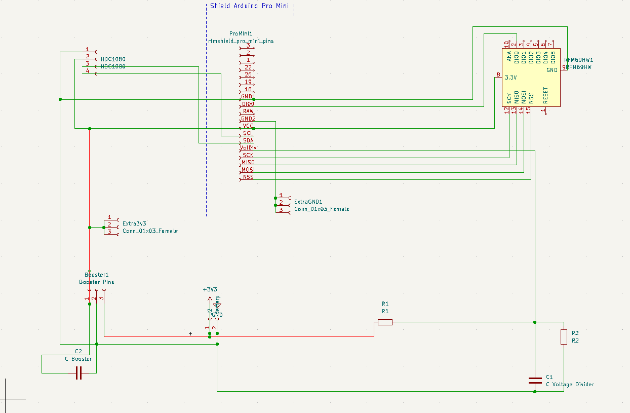
WIP: My first PCB: Arduino Pro Mini + RFM69 small node (feedback wanted)Thank you for your feedback!
I have (or at least I think) a decoupling cap on the pcb (C2). And you are right, I should have added the schematics from the start.
I tried doing it on openhardware.io but now the pics of the pcb itself show an older version (the schematics are fine though, I'll add them here too).
I added pins for a HDC1080 temperature/humidity sensor, because that's what I'll probably end up adding anway.
1 interrupt should be all that I need, but if I need more I'll probably use this workaround. But thank you for letting me know about the micro, didn't even know that existed :)
-
Tips/Tricks for placing sensors above doors?Hi,
How do you attach/place your sensor boxes close to the door in a way that is visually appealing but also doesn't make it too hard to get to the sensor for code and battery changes?
I thought about Tesa Power Strips but maybe there are better solutions out there?
-
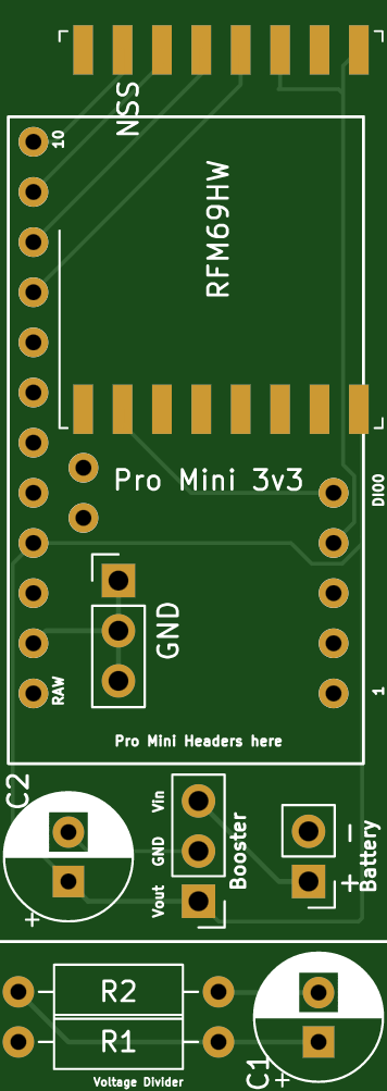
WIP: My first PCB: Arduino Pro Mini + RFM69 small node (feedback wanted)Hi,
To increase the WAF of my door/window sensors I created this small PCB. It connects a RFM69 to an Arduino Pro Mini with the lowest footprint I could come up with. There is additional space for a booster and a voltage divider though the voltage divider is optional (Just cut it if you don't need it).
Criticism/Feedback and everything in between is very much welcome since I literally have no idea what I am doing and I hope somebody can point out issues before I order my first batch. So: so far this is untested, please don't order it until I got my hands on the first batch.
I was also hoping that somebody could tell me how to set up the project so that mysensors gets a few dollars for every ordered batch, I've seen other projects do that and I want to give back to the community too.
If, unexpectedly, there are no issues with the PCB the next step in the project will be to create a 3D-printable enclosure (I am leaning towards tinkercad, but again, I have no idea what I am doing and I am open to suggestions).
-
💬 RFM69(H)W Arduino Mini Pro Shield v2Does anybody have a link to a fixed version of this board? It's exactly what I am looking for form-wise, but I'd be nice if VCC was wired to 3.3v out of the box. Thanks!!
-
Starting my PC with a 3.3v arduino pro mini?So, I finally got this done and it works just like I want it to. I used my initial schematics (plus radio, of course) and this code:
/**
 * The MySensors Arduino library handles the wireless radio link and protocol
 * between your home built sensors/actuators and HA controller of choice.
 * The sensors forms a self healing radio network with optional repeaters. Each
 * repeater and gateway builds a routing tables in EEPROM which keeps track of the
 * network topology allowing messages to be routed to nodes.
 *
 * Created by Henrik Ekblad <henrik.ekblad@mysensors.org>
 * Copyright (C) 2013-2015 Sensnology AB
 * Full contributor list: https://github.com/mysensors/Arduino/graphs/contributors
 *
 * Documentation: http://www.mysensors.org
 * Support Forum: http://forum.mysensors.org
 *
 * This program is free software; you can redistribute it and/or
 * modify it under the terms of the GNU General Public License
 * version 2 as published by the Free Software Foundation.
 *
 *******************************
 *
 * REVISION HISTORY
 * Version 1.0: Yveaux
 *
 * DESCRIPTION
 * This sketch provides an example of how to implement a humidity/temperature
 * sensor using a Si7021 sensor.
 *
 * For more information, please visit:
 * http://www.mysensors.org/build/humiditySi7021
 *
 */

// Enable debug prints
#define MY_DEBUG

#define MY_OWN_DEBUG

#ifndef MY_OWN_DEBUG //disable serial in production compile, potentially saves few uA in sleep mode
     #define MY_DISABLED_SERIAL
#endif


// Enable and select radio type attached
#define MY_RADIO_RFM69
#define MY_IS_RFM69HW
#define MY_RFM69_NEW_DRIVER


#define MY_NODE_ID 5
#define CHILD_ID_TXT 0
#define OUTPIN 8
#include <MySensors.h>


#define SKETCH_NAME "media_pc_switch"
#define SKETCH_MAJOR_VER "1"
#define SKETCH_MINOR_VER "0"

static bool metric = true;

MyMessage msgTxt(CHILD_ID_TXT, V_TEXT);
void presentation()
{
   // Send the sketch version information to the gateway and Controller
  sendSketchInfo(SKETCH_NAME, SKETCH_MAJOR_VER "." SKETCH_MINOR_VER);
  present(CHILD_ID_TXT, S_INFO);
}
void setup()
{
   pinMode(OUTPIN, OUTPUT);    //
   digitalWrite(OUTPIN, LOW);
   #ifdef MY_OWN_DEBUG
      Serial.print("Starting: ");
  #endif
  send(msgTxt.set("Ready"));
}

void receive(const MyMessage &msg)
{
  uint16_t ms;
  Serial.print("Received a message: ");
  Serial.println(msg.getString());
  send(msgTxt.set(msg.getString()));
  ms = msg.getUInt();
  if (ms > 10000 || ms < 1){return;}
  send(msgTxt.set("Received"));
  Serial.println("Pulling pin high");
  digitalWrite(OUTPIN, HIGH);
  Serial.print("Waiting for "); Serial.println(ms);
  delay(ms);
  Serial.println("Switching off");
  digitalWrite(OUTPIN, LOW);
  Serial.println("Delaying a few seconds to ignore message resends.");
  send(msgTxt.set("Sleeping"));
  delay(10000);
  send(msgTxt.set("Ready"));


}
Now I can use this sequence in HA to start my PC even when the power was cut:
wzimmer_ms_start_htpc:
  alias: Use mysensors node 5 to start the mediapc in the living room
  sequence:
    repeat:
      sequence:
        #don't run if htpc already running
          - condition: not
            conditions:
            - condition: state
              entity_id: binary_sensor.htpc
              state: 'on'
        #send start signal to mysensors
          - service: notify.mysensors
            data:
              target: "media_pc_switch 5 0"
              message: 1000
        #wait for timeout seconds whether a message has been received
          - wait_for_trigger:
            - platform: state
              entity_id: sensor.media_pc_switch_5_0
              to: "Received"
            timeout: '00:00:04'
      until:
          # Did it work?
          - condition: state
            entity_id: sensor.media_pc_switch_5_0
            state: Received
Thank you, @cabat for your help and your patience!!! :)
-
Starting my PC with a 3.3v arduino pro mini?If I wanted this protection where would I put it in my schematic? :)
Between ground an 3.3v?
/edit: no between the arduino and 3.3v from the Mainboard, right?
-
Starting my PC with a 3.3v arduino pro mini?Ah, ok, I get it now. The diode protects me from wiring this up with POWER and GND switched. So I would use it like this
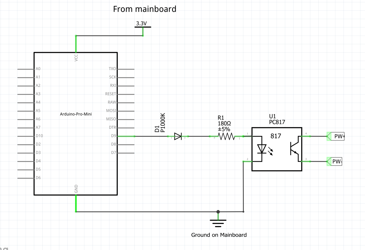
But I guess I can't because of the voltage drop. I think that's out of specs for the PC817. And anyway there is a very low chance that I will wiring this side of the schematic up wrong.
I guess I was just confused by the lower part of your drawing.
Thank you VERY much for your patience! I'll supply pictures when I have this hooked up in the hopes they will help others.
Have a nice weekend!
-
Starting my PC with a 3.3v arduino pro mini?To protect from polarity reversing, like you did in your sketch. Sorry if that's a stupid question!
-
Starting my PC with a 3.3v arduino pro mini?Cool, thank you for your help!
Should I use a diode between 3.3v and GND too? And do I need a resistor in the mainboard-side of the schematic? Some people used them to protect the optocoupler from high current but I guess there isn't a high current when the power button is pressed?
-
Starting my PC with a 3.3v arduino pro mini?So I think I understand the main part of your drawing: The optocoupler keeps the Arduino circuit separate from the mainboard circuit to prevent a short. The resistor is for the diode inside the optocoupler.
There are a few things about your drawing that I don't understand:
- Why is there a 5V powerline with a diode?
- What does the MB stand for? Mainboard
- Why are there two connection points from the Mainboard? Is one reset?
I tried my first Fritzing to make sense of this and to show how I would design the connections (doesn't mean it's right).
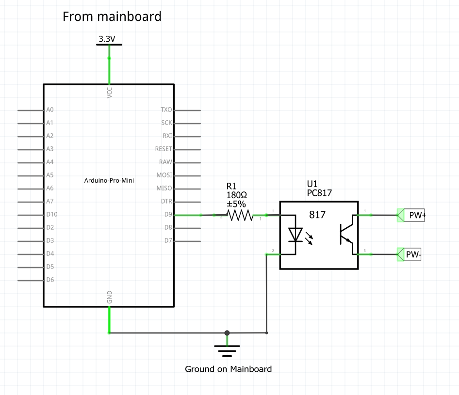
PW+ and PW- are the pins from the schematic in the first post. , 3,3V and GND are available on another set of pins on the mainboard. Would this work?
-
Starting my PC with a 3.3v arduino pro mini?Thank you. It seems I have some groundwork to do and learn how to read the schematics :D That hasn't been necessary until now. I'll do that and come back here when I understand enough
-
Starting my PC with a 3.3v arduino pro mini?Hi,
I'd like to start my PC using an Arduino Pro Mini (3.3v) but I am not sure how to hook it up.
There are a lot of tutorials (if you include esp8266 devices) but I am not sure which parts I exactly need. In essence I need to pull the power pin high that is connected to the power button (if I understood correctly).
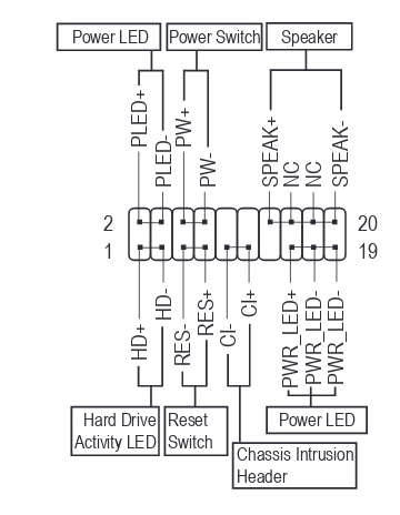
So on my mainboard (Gigabyte Aorus B450M) that means I connect RES+ to a pin on my arduino and RES- to GND, right?
There is a 3.3v pin on the mainboard (schematic), can I connect the arduino to that pin to power it?
And the most important question: Do I need any other parts? Is the voltage higher on RES+? Does that mean it can fry my arduino?
And in case the question comes up: I can't use wol because I disconnect the PC from power when off. That is apparently against the wol specs and only works in a few cases (of which my mainboard apparently isn't one).
Thanks for any help!
-
[SOLVED] Dropped node: arduino blinks only onceSeems you where both right. A short drained the battery (which I didn't notice) and getting rid of the short and using a new set of rechargeables solved the problem.
Thank you very much!
-
[SOLVED] Dropped node: arduino blinks only onceHi,
sorry for the cryptic topic-name, I'll try to elaborate.
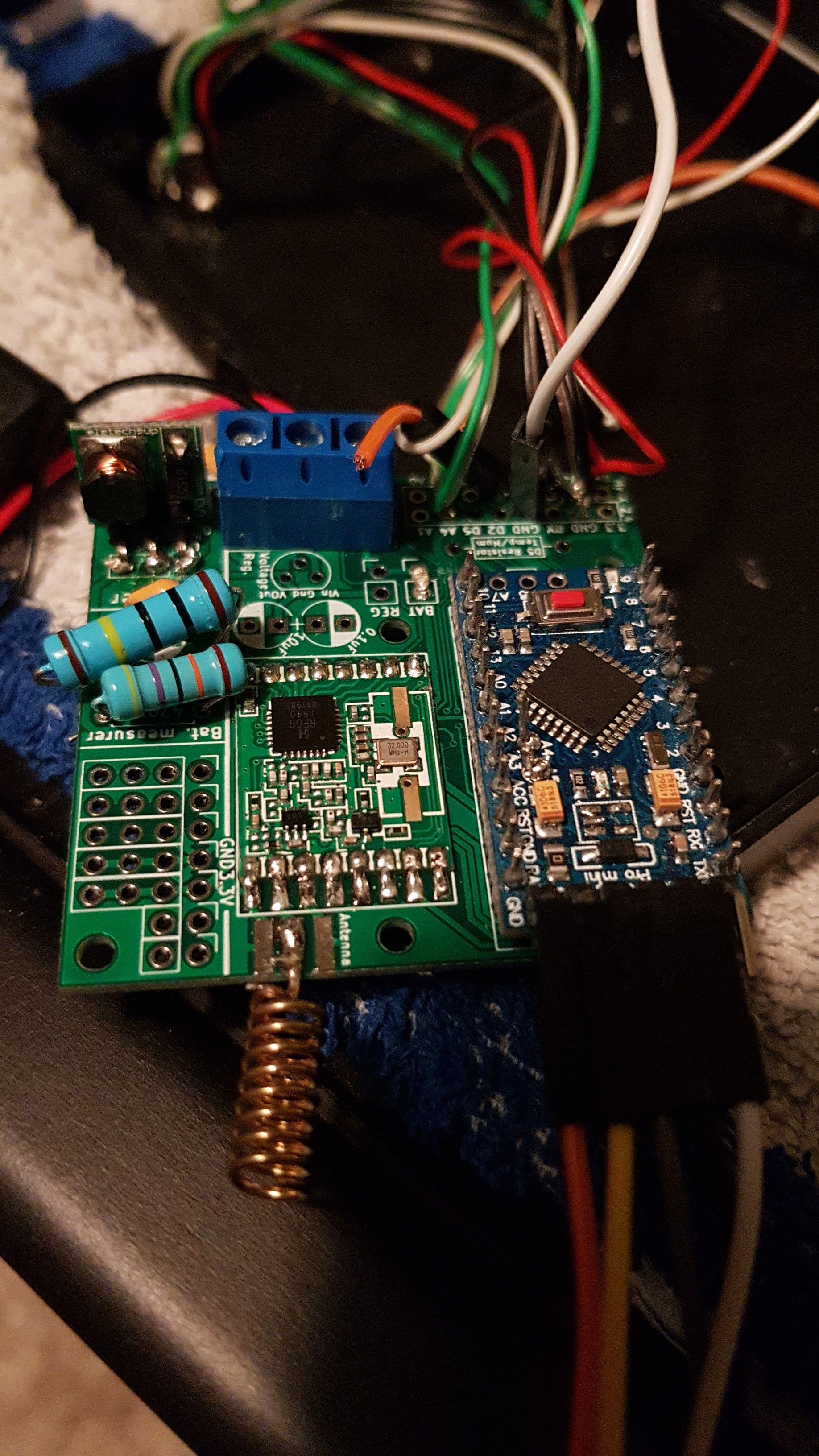
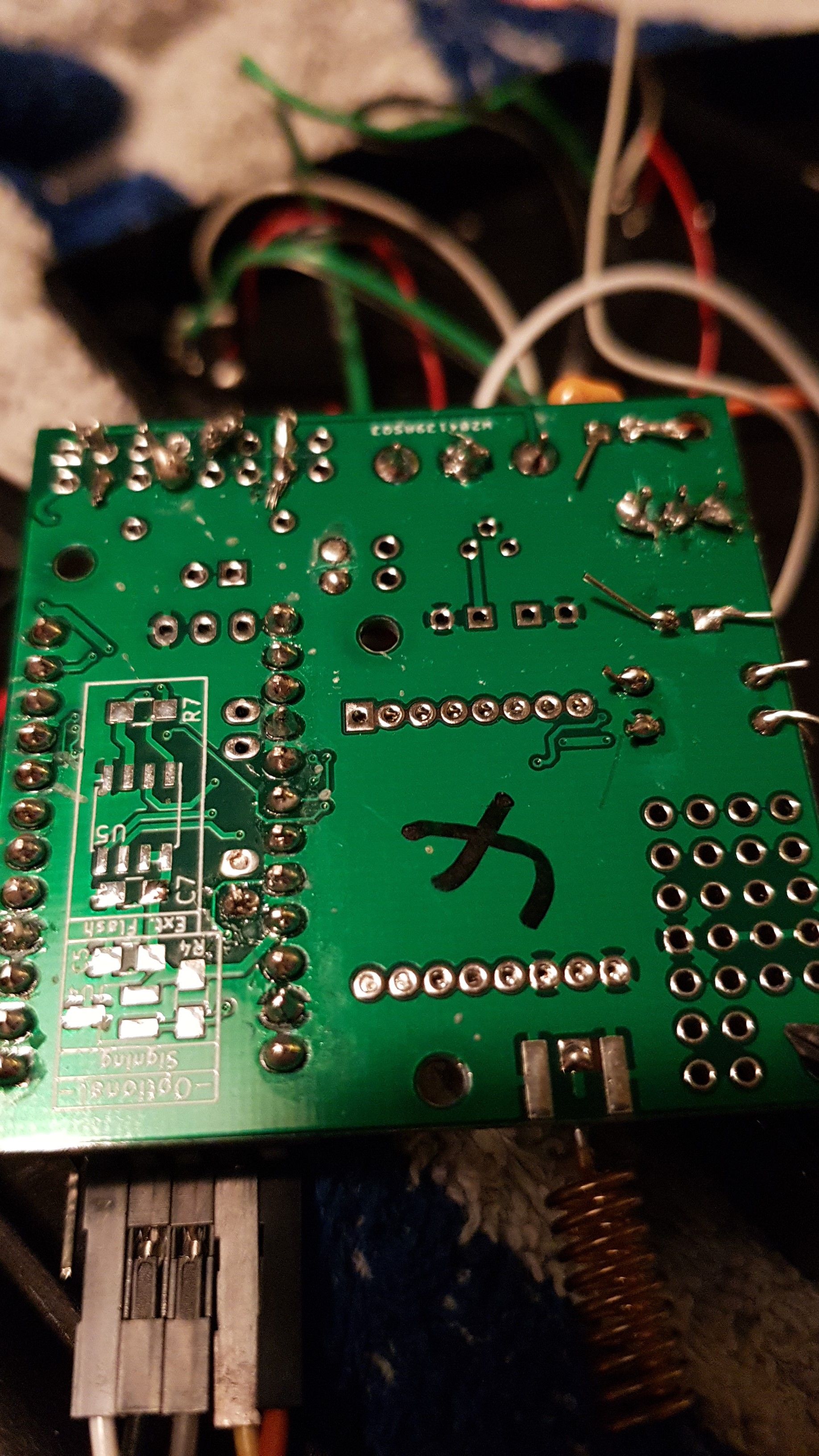
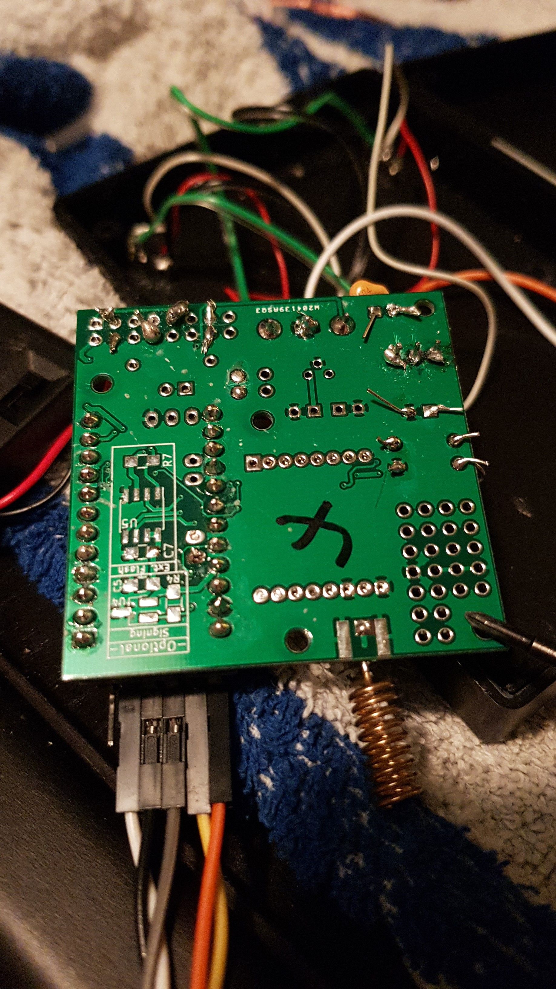
I have build a node with an arduino pro mini 3.3, an rfm69, a temp sensor, a lux sensor and a door sensor using the easypcb. The node worked flawlessly and I mounted it above the door I wanted to monitor. Unfortunately I mounted it rather badly and it came down after two weeks.
It didn't turn on again and I saw that a part of the step up booster came loose, so I replaced the step up booster.
When I now attach my batteries to it (2 AA rechargables, 1.6V in total, measured with my multimeter) the status-led (not the power led, I desoldered that one) blinks shortly once but then stays silent and I am not receiving any messages on the gateway.
It all works as expected if I power the arduino with the FTDI-serial-adapter so I think the arduino is ok?
Two things I noticed: When I switch battery power on the status led blinks once, as I said. When I then turn the power off and immediately back on again it doesn't blink. I have to wait some time before it blinks again.
I measured the voltage at the screw terminal and there it is only 0.4V instead of the 1.6V I see when I measure it at the cables of the battery holder directly. I don't know whether that's expected or not, but I wanted to mention it.
Here are pictures of the node:
Thanks for any help!