Skip to content
  • OpenHardware.io
  • Categories
  • Recent
  • Tags
  • Popular
Skins
  • Light
  • Brite
  • Cerulean
  • Cosmo
  • Flatly
  • Journal
  • Litera
  • Lumen
  • Lux
  • Materia
  • Minty
  • Morph
  • Pulse
  • Sandstone
  • Simplex
  • Sketchy
  • Spacelab
  • United
  • Yeti
  • Zephyr
  • Dark
  • Cyborg
  • Darkly
  • Quartz
  • Slate
  • Solar
  • Superhero
  • Vapor

  • Default (No Skin)
  • No Skin
Collapse
Brand Logo
mfalkviddM

Mikael Falkvidd

@mfalkvidd
Mod
  • Getting Started
  • Controller
  • Build
  • Hardware
  • Download/API
  • Forum
  • Store
About
Posts
5.5k
Topics
67
Shares
0
Groups
3
Followers
47
Following
261

Posts

Recent Best Controversial

  • MySensors 2.2.0 released
    mfalkviddM mfalkvidd
    • Bug fixes - thanks to everyone who contributed in troubleshooting and tracking down problems
    • Improved documentation, available at https://www.mysensors.org/apidocs/index.html
    • NRF5 improvements
    • A lot more, the changelog is looong :-) For full list, see https://github.com/mysensors/MySensors/releases/tag/2.2.0 and https://github.com/mysensors/MySensors/compare/2.1.1…2.2.0

    Big thanks to the following people who contributed to the release (151 commits in total):

          1 bilbolodz
         17 d00616
          2 Dustin
          3 Yveaux
          1 FotoFieber
          1 Frank Holtz
          1 Frédéric FRANCE
          1 freynder
          1 Krister W
          1 Lee Nelson
         20 Marcelo Aquino
         12 Mikael Falkvidd
         16 Patrick Fallberg
          1 per1234
          3 Rainer Clasen
          1 rejoe2
          1 Soef
         67 tekka
          1 Thomas Mørch
    

    Mixing different 2.x versions in the same MySensors network is OK, so you can start deploying new nodes with 2.2.0 without re-flashing your existing nodes, and you can upgrade your gateway without upgrading the nodes.

    The new version should be available in the Arduino IDE within a few days now.

    Announcements

  • Step-by-step procedure to connect the NRF24L01+ to the GPIO pins and use the Raspberry as a Serial Gateway (MySensors 1.x)
    mfalkviddM mfalkvidd

    Note: This guide is only applicable to MySensors 1.x. For MySensors 2, use this guide.

    I noticed that a step-by-step procedure to connect the NRF24L01 to the GPIO pins and use the Raspberry as a Serial Gateway was listed in the document for MySensors 1.6.

    Since I have three gateways configured this way, and I need to set up 3 more for covering different offices around the world, and I had already written the instructions in Swedish for Datormagazin, I thought I'd help out.

    This is the first draft. Any feedback is welcome.


    INTRODUCTION
    The radio module NRF24L01+ is cheap and power efficient, but it is unable to communicate with regular wifi. The bridge between NRF24L01+ nodes and the "computer world" is called a Gateway. You can use other types of gateways, but connecting the NRF24L01+ module directly to the Raspberry Pi is a simple and cheap alternative.

    Wiring Things Up
    Connect the NRF20L01+ radio module to the Raspberry Pi like this:
    raspi_mysensors[1].png

    Raspberry Pi NRF24L01+ Color
    6 / GND GND Black
    1 / 3.3V DC VCC Red
    22 / GPIO25 CE Orange
    24 / GPIO 8 CSN/CS Yellow
    23 / GPIO11 / SPI_CLK SCK Green
    19 / GPIO10 / SPI_MOSI MOSI Blue
    21 / GPIO9 / SPI_MISO MISO Violet

    The IRQ pin on NRF24L01 is not currently used.

    For a comprehensive view of the Raspberry Pi pins, see http://pinout.xyz/

    You should also connect a decoupling capacitor to the radio. See this guide.

    COMPILING THE GATEWAY
    Login to your Raspberry Pi (using SSH or open a terminal on the graphical console) and run these commands:

    git clone https://github.com/TMRh20/RF24.git
    cd RF24
    make all && sudo make install
    cd ..
    
    git clone https://github.com/mysensors/Raspberry.git
    cd Raspberry
    make all && sudo make install
    

    If you get the following error:

    pi@raspberrypi ~/RF24 $ make all && sudo make install
    g++ -Wall -fPIC -Ofast -mfpu=vfp -mfloat-abi=hard -mtune=arm1176jzf-s -march=armv7-a -D BCM2835_PERI_BASE=0x -c RF24.cpp
    gcc -Wall -fPIC -Ofast -mfpu=vfp -mfloat-abi=hard -mtune=arm1176jzf-s -march=armv7-a -D BCM2835_PERI_BASE=0x -c bcm2835.c
    bcm2835.c: In function ‘bcm2835_init’:
    bcm2835.c:1207:28: error: invalid suffix "x" on integer constant


    You've probably run into the problem discussed in this thread. People have had luck with different solutions. The simplest is to make the following change to ~/Raspberry/librf24-bcm/Makefile

    #IOBASE := $(shell cat /proc/iomem | grep bcm2708_vcio | cut -f 1 -d "-")
    IOBASE := 3F000000
    

    VERIFY THE GATEWAY
    Run sudo /usr/local/sbin/PiGatewaySerial. The output should look like this:

    pi@raspberrypi ~/Raspberry $ sudo /usr/local/sbin/PiGatewaySerial
    Starting PiGatewaySerial...
    Protocol version - 1.4
    Created PTY '/dev/pts/1'
    Gateway tty: /dev/ttyMySensorsGateway
    ================ SPI Configuration ================
    CSN Pin          = CE0 (PI Hardware Driven)
    CE Pin           = Custom GPIO25
    Clock Speed      = 8 Mhz
    ================ NRF Configuration ================
    STATUS           = 0x0e RX_DR=0 TX_DS=0 MAX_RT=0 RX_P_NO=7 TX_FULL=0
    RX_ADDR_P0-1     = 0xe7e7e7e7e7 0xc2c2c2c2c2
    RX_ADDR_P2-5     = 0xff 0xc4 0xc5 0xc6
    TX_ADDR          = 0xe7e7e7e7e7
    RX_PW_P0-6       = 0x00 0x00 0x20 0x00 0x00 0x00
    EN_AA            = 0x3b
    EN_RXADDR        = 0x07
    RF_CH            = 0x4c
    RF_SETUP         = 0x23
    CONFIG           = 0x0e
    DYNPD/FEATURE    = 0x3f 0x06
    Data Rate        = 250KBPS
    Model            = nRF24L01+
    CRC Length       = 16 bits
    PA Power         = PA_LOW
    

    If the NRF24L01+ isn't correctly wired, the following error will be shown

    pi@raspberrypi ~ $ sudo /usr/local/sbin/PiGatewaySerial
    Starting PiGatewaySerial...
    Protocol version - 1.4
    Created PTY '/dev/pts/2'
    Gateway tty: /dev/ttyMySensorsGateway
    check wires
    

    If this happens, double-check your wiring and correct any problems. Press Ctrl+Z and type

    sudo killall PiGatewaySerial
    

    to get rid of the non-functioning Gateway. Then run sudo /usr/local/sbin/PiGatewaySerial again

    If all is well, exit PiGatewaySerial by pressing Ctrl+C. Then run

    sudo /etc/init.d/PiGatewaySerial start
    

    to start the gateway as a background process. Verify that it started correctly by running

    sudo cat /dev/ttyMySensorsGateway
    

    You should see the message "Gateway startup complete". Exit by typing Ctrl+C.

    MAKE THE GATEWAY AUTOSTART
    To make sure the Gateway is started when your Raspberry Pi boots up, run the following command:

    sudo make enable-gwserial
    

    Enable the gateway for use with Domoticz
    Domoticz (and maybe other home automation systems) has trouble reading from the default path created by PiGatewaySerial. You might need to run the following command:

    sudo ln -s /dev/ttyMySensorsGateway /dev/ttyUSB20
    

    And change /etc/rc.local from this

    exit 0


    to this

    ln -s /dev/ttyMySensorsGateway /dev/ttyUSB20
    exit 0


    OTHER NOTES

    • The 3.3V power on the Raspberry Pi is rated for a maximum of 50mA. A regular NRF24L01+ only needs 15mA, but if you are using a power amplified version you might exceed what the Raspberry Pi can output. In that case, an external power supply might be required. If you use an external power source gnd must be connected to the Raspberry Pi's gnd.

    • Connecting the NRF24L01+ directly to your Raspberry Pi will prevent you from using the Raspberry Pi's gpio ports for other things, like a Z-wave board.

    • A user experienced slow data transfer compared to USB-to-Serial(ttl)<-->MySensors Gateway connection, especially on OTA firmware update. If you think this will cause a problem for you, an ethernet gateway might be a better alternative.

    As always, I stand on the shoulders of giants. Related posts:

    • http://forum.mysensors.org/topic/1151/tutorial-raspberry-pi-nrf24l01-direct-connection
    • http://forum.mysensors.org/topic/1974/domoticz-as-controller-and-a-gateway-for-mysensor-nodes-running-on-a-raspberry-pi-2

    TROUBLESHOOTING
    If you get this error

    pi@Domoticz3:~/Raspberry$ sudo /etc/init.d/PiGatewaySerial start
    [....] Starting PiGatewaySerial (via systemctl): PiGatewaySerial.serviceFailed to start PiGatewaySerial.service: Unit PiGatewaySerial.service failed to load: No such file or directory.
     failed!
    

    or this error

    pi@raspberrypi ~ $ sudo /usr/local/sbin/PiGatewaySerial
    sudo: /usr/local/sbin/PiGatewaySerial: command not found
    

    you have probably forgotten to run sudo make install. Read the instructions again, and follow them this time :-) User @sineverba reported that a reboot of the Pi after running make install helped.

    Hardware nrf24 raspberry pi raspberry raspberry nrf24l01 gpio gateway

  • MySensors-powered arcade game screen with wireless gamepad controller
    mfalkviddM mfalkvidd

    OK, I realize that I am abusing the MySensors library a bit here :-)

    I have built a 9x16 pixel, 22" led screen after my last failure. The screen was inspired by this instructable.

    I have also built a wireless gamepad controller:
    0_1481918125040_DSC02831.jpg
    I wanted a barebone look, so I decided to build it directly on a 5x7cm prototype board. On the back is a 2xAA battery holder that is glued to the board. Raw and simple :)

    The gamepad uses a nrf24l01+ and a 3.3V Arduino Pro Mini. When powered up, it presents 6 switches to the "gateway", using MySensors.

    The "gateway" is a Wemos D1 Mini connected to the big screen seen below:
    0_1481919082873_DSC09768.jpg
    I merged the standard MySensors serial gateway sketch with a sketch for playing Tetris, and modified the game to read the status of the switches instead of using locally attached buttons.

    I am using the development branch of MySensors since v2.0 doesn't call receive() on the gateway.

    All kudos for the game should go to Aaron Liddiment, https://github.com/AaronLiddiment/LEDSprites - I did not write the game myself.

    Here is the result:
    https://youtu.be/Mq9ad47P9cI

    The wemos + screen draws less than 1 ampere, so a USB power pack can power it for hours. That means the game is portable and can be used anywhere. It would be fun to play it on the bus/train :sunglasses:
    Some thoughts for future development:

    • Add signing and see if that has a negative impact on the gaming experience. I don't want anyone sending fake button presses!
    • Figure out how to handle the screen flickering that happens sometimes. There is a very long thread about this on github: https://github.com/FastLED/FastLED/issues/306
    • Add more games. Snake, Pong, Sokoban, Breakout - ideas are very welcome :ear:
    • Build one more wireless controller for multiplayer games
    • Add the ability to use the screen as mood light when not playing.
    • Add the ability to show weather when not playing a game (temperature as text, yellow background when sunny, blue/gray "falling" background when raining, etc)
    • Use fadecandy
    • Spectrum analyzer
    My Project esp8266

  • MySensors 2.3.1 released
    mfalkviddM mfalkvidd

    As an early holiday gift, MySensors 2.3.1 has been released.

    Highlights
    RF24: Add delay after power-up
    RFM69 frequency band support for India
    Improve transport function & debug messages
    Allow flash strings in present() to save RAM

    Release notes and changelog: https://github.com/mysensors/MySensors/releases/tag/2.3.1

    Important information:

    • The NRF24 defines have been renamed to RF24 to use naming that's consistent with the other transport defines.
    • ESP8266 board definitions 2.4.2 or later are REQUIRED for use with this release. If you use ESP8266 board definitions 2.4.1 or earlier you will get an error saying fatal error: gdb_hooks.h: No such file or directory #include "gdb_hooks.h"

    Thanks to all GitHub users who contributed to this release:

    • freynder
    • Jeeva Kandasamy
    • Lee Nelson
    • tekka
    • Yveaux
    • Marcelo Aquino
    • Mikael Falkvidd
    • Patrick Fallberg
    Announcements

  • Office plant monitoring
    mfalkviddM mfalkvidd

    I work as development team lead at a software company. We do server and network monitoring. Yesterday we hosted a customer event, and I presented my houseplant monitoring project based on MySensors and Domoticz. The presentation was a hit, and it has been decided that we'll use MySensors to monitor all plants at the office.

    There is not that much to tell from a technical perspective. I hooked up everything according to the MySensor build page and created a simple sketch.

    Thanks to everyone from the MySensors community for a great library, clear instructions and great suggestions for projects. And thanks for making me look like a hero :-D Let's continue conquering the world.

    My Project

  • Physical mood light color and brightness selector based on LCD touchscreen (with demo video)
    mfalkviddM mfalkvidd

    Alright. I have a project to tell you about. If there was an award for the most needlessly laborious project in the MySensors contest, I think I would have a good shot but since there is no such award I'll just post it here for fun :-)

    I don't remember where I got the idea from, but the basic idea is a physical color selector for a mood light. A LCD touch display can be mounted inside a regular switch/dimmer wall enclosure. The light level and the color of the mood light is set by touching the display. Physical light switches are conveniently located throughout the house and anyone can use them - you don't need a smartphone with an app.

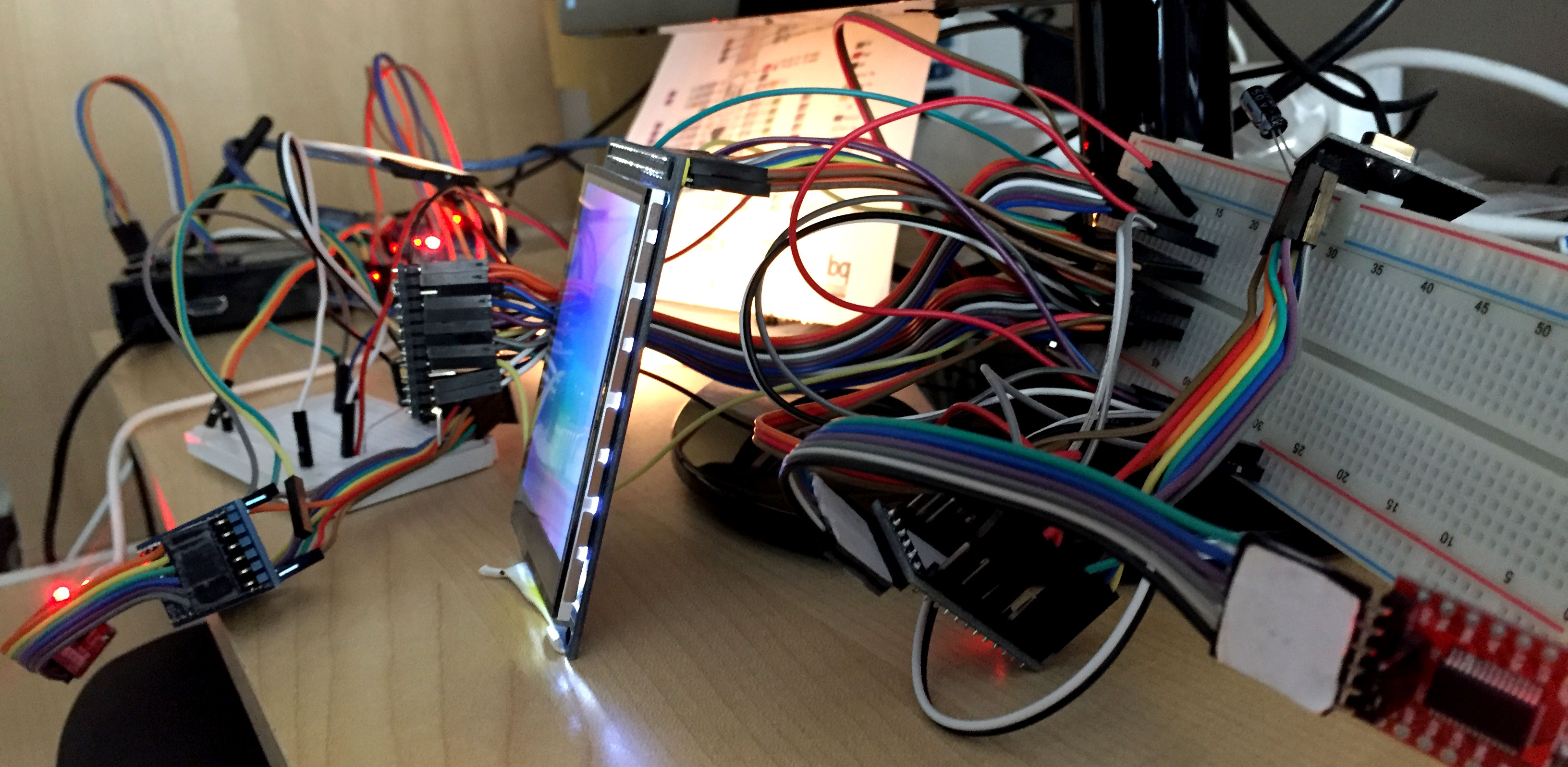
    So I ordered a 3.2" lcd touch screen. It arrived from China, and I realized I had bought a screen with a 16-bit bus. 16 bit bus means I need to have 16 data pins to send data to the screen. And that is for the data bus only. More pins are needed (RSET, LCD_CS, WR and RS). With an Arduino Mega this would not be a problem, but I only have Pro Minis.

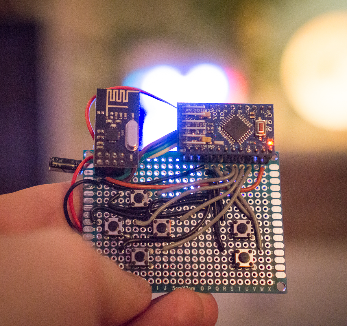
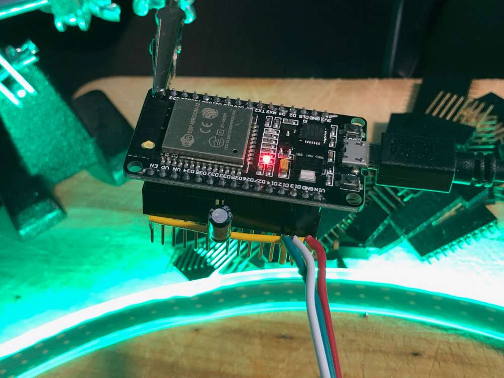
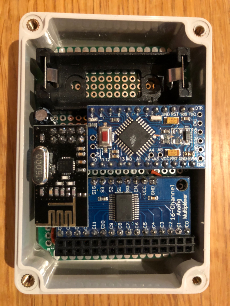
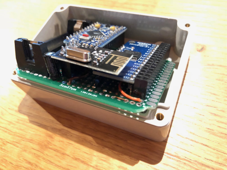
    I figured out how to connect the screen. If I used ALL available pins on the Pro Mini (including the serial RX/TX, so no debugging :scream: ) I could make it show what I wanted. The breadboard setup is really a mess:
    0_1458382025681_breadboard.jpg

    So now I have an Arduino connected to a screen, that can show anything pre-defined. But there is no room for a radio or anything else to use for telling the Arduino what to show on the screen. Or is there? I realized that the LCD_CS pin on the screen can be set to high always. So I connected that to Vcc instead of using one of my precious i/o pins. I now have 1 pin available :exclamation:

    The Arduino Software Serial functions can use any pin for serial communication. 1 available pin means one-way communication. I hooked up another Pro Mini (the flash storage was getting pretty crowded on the first Pro Mini anyway so it was nice to start fresh). Using the Software Serial function I could now send characters from the second Pro mini (called "Touch Dimmer) to the first Pro Mini (called "screen driver"). I can't get any information back, but that's ok.

    Next step was to define a set of commands that the Touch Dimmer Arduino could send to the Screen Driver Arduino. As of now, they look like this:

    fillScr(r,g,b) // Fills the entire screen with the r,g,b color
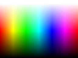
    drawHSL        // Draws a HSL color picker on the screen
    

    So by sending the text

    fillScr(FF,00,00)
    

    to the Screen Driver, I will fill the entire screen with red. By sending

    drawHSL
    

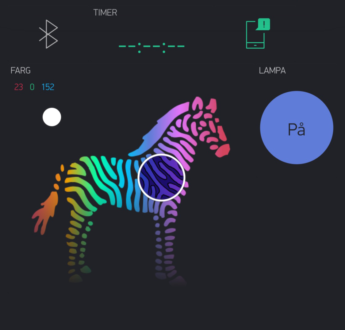
    the Screen Driver will draw a HSL color palette on the screen like this:
    0_1458381416800_hsl_whitetop.png

    I connected the touch sensor to the Touch Dimmer Arduino and set it up so that when the screen is touched, a color is sent to the mood light.

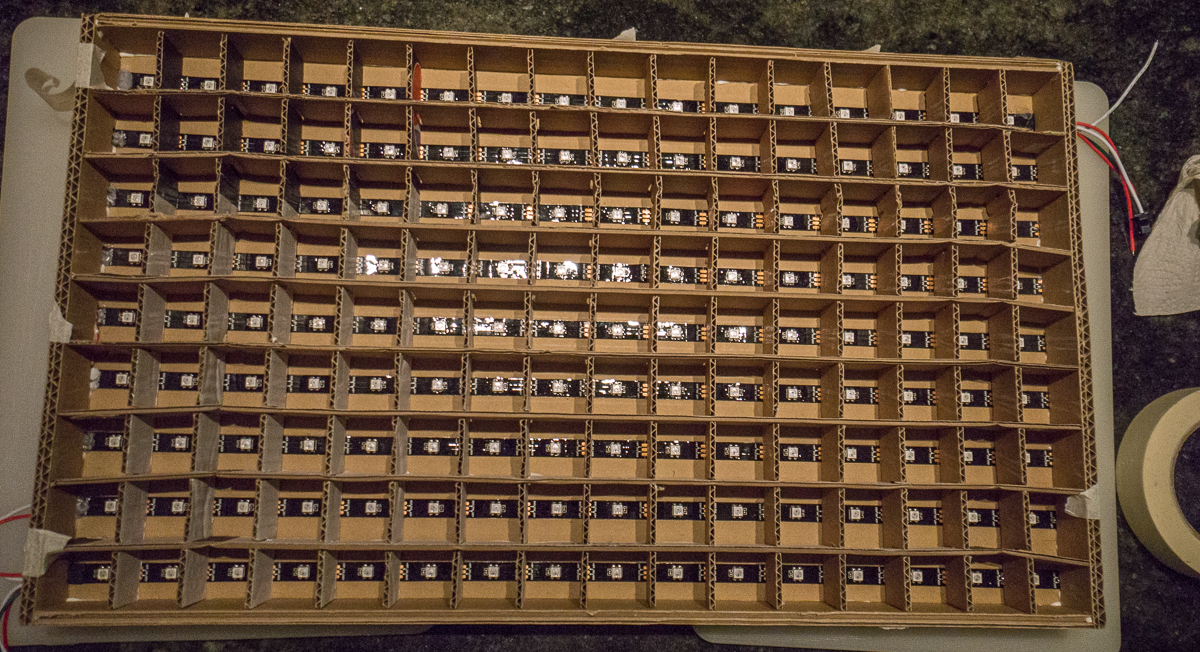
    For the mood light I used a slightly modified version of @AWI's great mood light from this thread.

    As can be seen in this video, selecting color and brightness by pressing on the screen works pretty OK.
    https://www.youtube.com/watch?v=PBPYastmasQ

    The sketches I use:
    Screen Driver

    #include <UTFT.h>
    #define NUM_WHITE_PIXELS 20
    #define RED 0
    #define GREEN 1
    #define BLUE 2
    #define SCALE 1
    //unsigned int hsl[240 / SCALE];
    extern unsigned int hsl[0x2170];
    //#define DEBUG
    // Declare which fonts we will be using
    //extern uint8_t SmallFont[];
    
    UTFT screen(ILI9327, A5, A4, A6, A3);
    #include <SoftwareSerial.h>
    
    SoftwareSerial mySerial(A2, A7); // RX, TX. TX is not used in this sketch.
    const byte PRIMES[] = {2, 3, 5, 7, 11, 13, 17, 19, 23, 29, 31, 37, 41, 43, 47, 53, 59, 61, 67, 71}; // Used to hash the commands
    String message;
    
    
    void setup()
    {
      // Setup the LCD
      screen.InitLCD();
      //  screen.setFont(SmallFont);
      screen.clrScr();
      screen.setBrightness(255);
      mySerial.begin(57600);
    #if defined (DEBUG)
      Serial.begin(115200);
      Serial.println("Ready");
    #endif
    }
    
    void loop()
    {
      byte current_char = 0;
      while (true) {
        while (mySerial.available() > 0) {
          char c = mySerial.read();
          if (c == '\r' || c == '\n') {
            // We got a newline. That means end of message.
            if (current_char == 0) {
              // Some systems use \n for newline. Some \r. Some \r\n. In case of the last, we filter out the second character.
              continue;
            }
            handle_message(message);
            message = "";
            current_char = 0;
            continue;
          }
          // We got another character. Add it to the buffer.
          message = String(message + c);
          current_char++;
        }
      }
    }
    
    void handle_message(String message) {
      // 1. Split the message into command + the rest
      // 2. Create a hash of the command to make a switch statement work
      // 3. Let each case-switch parse the rest of the string
    
      int command_next_pos = message.indexOf(',');
      String command = message.substring(0, command_next_pos);
    
      unsigned long command_hash = hash(command);
    
    #if defined (DEBUG)
      Serial.print("case ");
      Serial.print(command_hash);
      Serial.print(": // ");
      Serial.println(command);
      Serial.println("");
      Serial.println("break;");
    #endif
      byte r, g, b, next_pos, pos;
    
      switch (command_hash) {
        case 1922:
    #if defined (DEBUG)
          Serial.println("TEST");
    #endif
          break;
        case 25880: // setBrightness
          // setBrightness is not supported by my screen. Implement later.
    
          break;
        case 5953: // fillScr(r,g,b)
          pos = command_next_pos;
          next_pos = message.indexOf(',', pos + 1);
    #if defined (DEBUG)
          Serial.print("pos=");
          Serial.println(pos);
          Serial.print("next_pos=");
          Serial.println(next_pos);
          Serial.print("message_first_substring=");
          Serial.println(message.substring(pos + 1, next_pos));
    #endif
          r = message.substring(pos + 1, next_pos).toInt();
          pos = next_pos;
          next_pos = message.indexOf(',', pos + 1);
          g = message.substring(pos + 1, next_pos).toInt();
          pos = next_pos;
          next_pos = message.indexOf(',', pos + 1);
          b = message.substring(pos + 1, next_pos).toInt();
    #if defined (DEBUG)
          Serial.print("fillScr(");
          Serial.print(r);
          Serial.print(",");
          Serial.print(b);
          Serial.print(",");
          Serial.print(g);
          Serial.println(")");
    #endif
          screen.fillScr(r, g, b);
          break;
        case 8260: // setColor
    
          break;
        case 20365: // setBackColor
    
          break;
        case 10548: // drawPixel
    
          break;
        case 7850: // drawLine
    
          break;
        case 7962: // drawRect
    
          break;
        case 24512: // drawRoundRect
    
          break;
        case 7917: // fillRect
    
          break;
        case 24403: // FillRoundRect
    
          break;
        case 13194: // drawCircle
    
          break;
        case 13149: // fillCircle
    
          break;
        case 9890: // printNumI
    
          break;
        case 9821: // printNumF
    
          break;
        case 4014: // lcdOff
          // lcdOff is not supported by my screen, but let's issue the command anyway
          //screen.lcdOff();
          break;
        case 2776: // lcdOn
          // lcdOn is not supported by my screen, but let's issue the command anyway
          //screen.lcdOn();
          break;
        case 5023: // drawHSL
          drawHSL();
          break;
    
      }
    }
    /*
    void drawHSL() {
        screen.drawBitmap(0, 0, 107, 80, hsl, 3);
    }
    */
    void drawHSL() {
      screen.fillScr(0,0,0);
      float hue;
      float saturation = 1;
      float lightness;
      unsigned int height = screen.getDisplayYSize();
      unsigned int width = screen.getDisplayXSize();
      byte rgb[3] = {0};
      for (unsigned int x = 0; x < width; x += SCALE) {
        hue = ((float)x) / width;
        for (unsigned int y = 0; y < height; y += SCALE) {
          lightness = ((float)y) / (height - NUM_WHITE_PIXELS); // top NUM_WHITE_PIXELS pixels represent white, full power
          hslToRgb(hue, saturation, lightness, rgb);
          screen.setColor(rgb[RED], rgb[GREEN], rgb[BLUE]);
          screen.drawPixel(x, y);
        }
      }
    }
    
    unsigned long hash(String command) {
      unsigned long hash = 0;
      for (int i = 0; i < command.length(); i++) {
        hash += PRIMES[i] * command[i];
      }
      return hash;
    }
    
    /**
    * Adapted from http://stackoverflow.com/questions/2353211/hsl-to-rgb-color-conversion
    * Converts an HSL color value to RGB. Conversion formula
     * adapted from http://en.wikipedia.org/wiki/HSL_color_space.
    * Assumes h, s, and l are contained in the set [0, 1] and
    * returns r, g, and b in the set [0, 255].
    *
    * @param   Number  h       The hue
    * @param   Number  s       The saturation
    * @param   Number  l       The lightness
    * @return  Array           The RGB representation
    */
    void hslToRgb(float h, float s, float l, byte * rgbIn) {
      float r, g, b;
    
      if (s == 0) {
        r = g = b = l; // achromatic
      } else {
        float q = l < 0.5 ? l * (1 + s) : l + s - l * s;
        float p = 2 * l - q;
        r = hue2rgb(p, q, h + 1.0 / 3);
        g = hue2rgb(p, q, h);
        b = hue2rgb(p, q, h - 1.0 / 3);
      }
      rgbIn[0] = min(r * 255, 255);
      rgbIn[1] = min(g * 255, 255);
      rgbIn[2] = min(b * 255, 255);
    }
    
    float hue2rgb (float p, float q, float t) {
      if (t < 0) t += 1;
      if (t > 1) t -= 1;
      if (t < 1.0 / 6) return p + (q - p) * 6 * t;
      if (t < 1.0 / 2) return q;
      if (t < 2.0 / 3) return p + (q - p) * (2.0 / 3 - t) * 6;
      return p;
    }
    

    Touch Dimmer

    #include <UTouch.h>
    #include <SoftwareSerial.h>
    #define DEBUG
    #include <MySensor.h>
    #include <SPI.h>
    
    #define SAVE_LIGHT_R 0
    #define SAVE_LIGHT_G 1
    #define SAVE_LIGHT_B 2
    const char INITIALCOLOR[] = "FFAA55";
    const byte PRIMES[] = {2, 3, 5, 7, 11, 13, 17, 19, 23, 29, 31, 37, 41, 43, 47, 53, 59, 61, 67, 71}; // Used to hash the commands
    
    SoftwareSerial screen(A7, A2); // RX, TX. RX is not used in this sketch.
    UTouch myTouch( 6, 5, 4, 3, 2);
    MySensor gw;
    MyMessage RGBMsg(0, V_RGB);
    MyMessage solidColorMsg(2, V_STATUS);
    MyMessage setColorMsg(3, V_TEXT);
    
    void setup() {
      solidColorMsg.setDestination(12);
      setColorMsg.setDestination(12);
      Serial.begin(115200);
      Serial.println("Starting setup");
      delay(10);
      myTouch.InitTouch();
      myTouch.setPrecision(PREC_HI); // We don't need speed so we might as well go for precision
      screen.begin(57600);
      Serial.println("gw begin starts");
      delay(10);
      gw.begin(incomingMessage, AUTO, false);
      Serial.println("gw begin finished");
      delay(10);
      gw.sendSketchInfo("Mood light touchscreen", "1.0");
      gw.present(0, S_RGB_LIGHT, "RGB");// present to controller
      Serial.println("Setup done");
      // TODO: Fetch current value from controller instead of using black
      String initialColorCmd = "drawHSL";
      screen.println(initialColorCmd);
    
    
    }
    
    void loop() {
      gw.process();
    
      long x, y;
      byte temp_R, temp_G, temp_B;
      while (myTouch.dataAvailable() == true)
      {
        myTouch.read();
        x = myTouch.getX();
        y = myTouch.getY();
        if ((x != -1) and (y != -1))
        {
          Serial.print(x);
          Serial.print(",");
          Serial.println(y);
          float hue = x / 320.0;
          float saturation = 1;
          float lightness = y / (240.0 - 20); // top 20 pixels represent white, full power
          byte rgb[3] = {0};
          hslToRgb(hue, saturation, lightness, rgb);
    
          String colorCommand = rgbarrayToString(rgb);
          String command = String("fillScr," + colorCommand);
          char colorMessage[7];
          rgbarrayToHexstring(rgb).toCharArray(colorMessage, 7);
          //gw.send(RGBMsg.set(colorMessage));
          //gw.send(updateColor.set(colorMessage));
          gw.send(solidColorMsg.set(true));
          gw.send(setColorMsg.set(colorMessage));
          //screen.println(command);
          //screen.flush();
          //Serial.println(command);
          gw.wait(100); // More frequent updates than this will just make the screen updates irratic
        }
      }
    }
    
    void incomingMessage(const MyMessage &message) {
    
      if (message.type == V_RGB) {
        String hexstring = message.getString();
        Serial.print("RGB command: ");
        Serial.println(hexstring);
        setColor(hexstring);
      }
    }
    
    void setColor(String hexstring) {
      byte r, g, b;
      unsigned long number = strtoul( &hexstring[0], NULL, 16);
      Serial.print("Color long: ");
      Serial.println(number);
      byte RValue = number >> 16;
      byte GValue = number >> 8 & 0xFF;
      byte BValue = number & 0xFF;
    
      Serial.print("Color: ");
      Serial.println(hexstring);
      Serial.print("Red: ");
      Serial.println(RValue);
      Serial.print("Green: ");
      Serial.println(GValue);
      Serial.print("Blue: ");
      Serial.println(BValue);
    
    }
    
    String rgbarrayToString(byte *rgb) {
      return String(String(rgb[0]) + "," + String(rgb[1]) + "," + String(rgb[2]));
    }
    String rgbarrayToHexstring(byte *rgb) {
      char hexString[7];
      for (byte i = 0; i < 3; i++) {
        sprintf(hexString + i * 2, "%02X", rgb[i]);
      }
      hexString[6] = '\0';
      return hexString;
    }
    
    /**
    * Adapted from http://stackoverflow.com/questions/2353211/hsl-to-rgb-color-conversion
    * Converts an HSL color value to RGB. Conversion formula
     * adapted from http://en.wikipedia.org/wiki/HSL_color_space.
    * Assumes h, s, and l are contained in the set [0, 1] and
    * returns r, g, and b in the set [0, 255].
    *
    * @param   Number  h       The hue
    * @param   Number  s       The saturation
    * @param   Number  l       The lightness
    * @return  Array           The RGB representation
    */
    void hslToRgb(float h, float s, float l, byte *rgbIn) {
      float r, g, b;
    
      if (s == 0) {
        r = g = b = l; // achromatic
      } else {
        float q = l < 0.5 ? l * (1 + s) : l + s - l * s;
        float p = 2 * l - q;
        r = hue2rgb(p, q, h + 1.0 / 3);
        g = hue2rgb(p, q, h);
        b = hue2rgb(p, q, h - 1.0 / 3);
      }
      rgbIn[0] = min(r * 255, 255);
      rgbIn[1] = min(g * 255, 255);
      rgbIn[2] = min(b * 255, 255);
    }
    
    float hue2rgb (float p, float q, float t) {
      if (t < 0) t += 1;
      if (t > 1) t -= 1;
      if (t < 1.0 / 6) return p + (q - p) * 6 * t;
      if (t < 1.0 / 2) return q;
      if (t < 2.0 / 3) return p + (q - p) * (2.0 / 3 - t) * 6;
      return p;
    }
    
    unsigned long hash(String command) {
      unsigned long hash = 0;
      for (int i = 0; i < command.length(); i++) {
        hash += PRIMES[i] * command[i];
      }
      return hash;
    }
    

    Mood Light

    /*
     PROJECT: MySensors / RGB light NEOPIXEL
     PROGRAMMER: AWI
     DATE: october 10, 2015/ last update: october 14, 2015
     FILE: AWI_RGB.ino
     LICENSE: Public domain
    
     Hardware: Nano and MySensors 1.5, Wall light 16 WS2812B leds (neopixel)
    
     Special:
        uses Fastled library with NeoPixel (great & fast RBG/HSV universal library)             https://github.com/FastLED/FastLED
    
     SUMMARY:
    
        Different patterns and brightness settings
    
        Button switches on/off and cycles through all Color patterns on long press
    
     Remarks:
        Fixed node-id
    
    */
    
    #include <MySensor.h>
    #include <SPI.h>
    #include <FastLED.h>                                        // https://github.com/FastLED/FastLED
    #include <Button.h>                                         // https://github.com/JChristensen/Button
    
    const int stripPin = 5 ;                                    // pin where 2812 LED strip is connected
    const int buttonPin = 4 ;                                   // push button
    const int numPixel = 12 ;                                   // set to number of pixels (x top / y bottom)
    
    const int NODE_ID = 12;                                    // fixed MySensors node id
    const int RGB_LightChild = 0 ;                              // Child Id's, standard light child on/off/ dim
    const int RGB_RGBChild = 1 ;                                // RGB light child (on/off/dim/color, if controller supports V_RBG))
    const int RGB_SolidColorChild = 2 ;                         // when set, node reads Color text from ColorTextChild
    const int RGB_TextColorChild = 3 ;                          // Holds Text value for color (custom colors from controller)
    const int RGB_AlarmPatternChild = 4 ;                       // Switches to alarm status
    const int RGB_NextPatternChild = 5 ;                        // Move to next pattern when set
    
    CRGB leds[numPixel];
    
    // Kelving colors: Light & daylight (in Fastled reference only)
    /// 1900 Kelvin Candle=0xFF9329 /* 1900 K, 255, 147, 41 */,
    /// 2600 Kelvin Tungsten40W=0xFFC58F /* 2600 K, 255, 197, 143 */,
    /// 2850 Kelvin Tungsten100W=0xFFD6AA /* 2850 K, 255, 214, 170 */,
    /// 3200 Kelvin Halogen=0xFFF1E0 /* 3200 K, 255, 241, 224 */,
    /// 5200 Kelvin CarbonArc=0xFFFAF4 /* 5200 K, 255, 250, 244 */,
    /// 5400 Kelvin HighNoonSun=0xFFFFFB /* 5400 K, 255, 255, 251 */,
    /// 6000 Kelvin DirectSunlight=0xFFFFFF /* 6000 K, 255, 255, 255 */,
    /// 7000 Kelvin OvercastSky=0xC9E2FF /* 7000 K, 201, 226, 255 */,
    /// 20000 Kelvin ClearBlueSky=0x409CFF /* 20000 K, 64, 156, 255 */
    
    char controllerRGBvalue[] = "FF9329";                       // Controller sent RGB value, default
    uint16_t curBrightness, actualBrightness, controllerRGBbrightness = 0x7F ;  // Brightness globals
    unsigned long updateBrightnessDelay, lastBrightnessUpdate ; // Brightness timers
    int RGBonoff ;                                              // OnOff flag
    
    enum { pSolid, pOff, pAlarm, pFire, pFire2, pCandle, pRainbow}  ;   // Pattern globals (stored in int for convenience)
    const int lastPatternIdx = pRainbow + 1 ;                   // use last pattern for patterncount
    int curPattern ;                                            // current pattern
    unsigned long updatePatternDelay, lastPatternUpdate ;       // Pattern timers
    
    #define RADIODELAY 250
    unsigned long idleTimer = millis() ;                        // return to idle timer
    int idleTime = 10000 ;                                      // return to idle after 10 secs
    
    // initialize MySensors (MySensors 1.5 style)
    MySensor gw;
    
    MyMessage lightRGBMsg(RGB_LightChild,  V_RGB);              // standard messages, light
    MyMessage lightdimmerMsG(RGB_LightChild , V_DIMMER);
    MyMessage lightOnOffMessage(RGB_LightChild, V_STATUS);
    
    Button myBtn(buttonPin, true, true, 20);                    //Declare the button (pin, pull_up, invert, debounce_ms)
    
    // Simple state machine for button state
    enum {sIdle, sBrightness, sPattern} ;                        // simple state machine for button press
    int State ;
    
    void setup() {
      FastLED.addLeds<WS2812, stripPin, GRB >(leds, numPixel) ;  // initialize led strip .setCorrection(TypicalLEDStrip);
    
      gw.begin(incomingMessage, NODE_ID, false);              // initialize MySensors
      gw.sendSketchInfo("AWI RGB Wall 0", "1.0");
      gw.wait(RADIODELAY);
      gw.present(RGB_RGBChild, S_RGB_LIGHT, "RGB Wall RGB 0");// present to controller
      gw.wait(RADIODELAY);
      gw.present(RGB_LightChild, S_LIGHT, "RGB Wall Light 0");
      gw.wait(RADIODELAY);
      gw.present(RGB_SolidColorChild, S_LIGHT, "RGB Set Solid color (text) 0");
      gw.wait(RADIODELAY);
      gw.present(RGB_TextColorChild, S_INFO, "RGB Wall textcolor 0");
      gw.wait(RADIODELAY);
      gw.present(RGB_AlarmPatternChild, S_BINARY, "RGB Wall Alarm 0");
      gw.wait(RADIODELAY);
      gw.present(RGB_NextPatternChild, S_BINARY, "RGB Wall Pattern 0");
    
      // initialize strip with color and show (strip expects long, so convert from String)
      for (int i = 0 ; i < 6 ; i++) {                         // get color value from EEPROM (6 char)
        controllerRGBvalue[i] = gw.loadState(i) ;
      }
      setLightPattern(pSolid, NULL) ;                         // default controller Solid
      FastLED.show();
      State = sIdle ;                                         // Initial state
      //randomSeed(analogRead(0));
    }
    
    // read button and act accordingly
    // short press: on/off
    // longer press: set patterns with following short press
    // long press: set brightness increase
    void loop() {
      gw.process();                                           // wait for incoming messages
      myBtn.read();                                           //Read the button (only read)
      unsigned long now = millis();                           // loop timer reference
      switch (State) {
        case sIdle:                                         // default state, browse through patterns
          if (myBtn.wasReleased()) {                      // light on/ off in idle
            RGBonoff = !RGBonoff ;                      // invert light state
            setLightPattern((RGBonoff == 1) ? pOff : pSolid, 100);
            gw.send(lightOnOffMessage.set(RGBonoff));   // and update controller
          } else if (myBtn.pressedFor(500)) {             // move to Pattern update state with long press
            idleTimer = now ;                           // return to idle after ...
            State = sPattern ;
          }
          break ;
        case sPattern:                                      // entered after long press
          if (myBtn.pressedFor(2000)) {                   // when press even longer move to Brightness update
            State = sBrightness ;
          } else if (myBtn.wasPressed()) {
            setLightPattern((curPattern + 1) % lastPatternIdx, 500 ); // increase pattern and wrap
            idleTimer = now ;
          } else if ( now > idleTime + idleTimer  ) {     // return to idle after ...
            State = sIdle ;
          }
          break ;
        case sBrightness:                                   // entered after looong press
          if (myBtn.wasPressed()) {                           // if pressed again increase brightness
            setLightBrightness((curBrightness + 1) % 0xFF, 0) ; // increase brightness and wrap (0..0xFF)
            idleTimer = now ;
          } else if ( now > idleTime + idleTimer  ) {     // return to idle after ...
            State = sIdle ;
          }
          break ;
        default :
          State = sIdle ;
          break ;
      }
      updateLightBrightness();                                // update Brightness if time
      updateLightPattern();                                   // update Pattern if time
    }
    
    // Sets the light brightness, takes value and time (ms) as input
    void setLightBrightness(int newBrightness, unsigned long updateTime) {
      // global: curBrightness, actualBrightness, updateBrightnessDelay
      updateBrightnessDelay = updateTime / 0xFF ;             // delay = time / max steps
      actualBrightness = curBrightness ;                      // assume curBrightness is actual
      curBrightness = newBrightness ;                         // set curBrightness to new value, rest is done in update
    }
    
    // Update the light brightness if time
    void updateLightBrightness() {
      // global: curBrightness, actualBrightness, updateBrightnessDelay, lastBrightnessUpdate ;
      unsigned long now = millis() ;
      if (now > lastBrightnessUpdate + updateBrightnessDelay) { // check if time for update
        if ( actualBrightness > curBrightness) {
          FastLED.setBrightness( actualBrightness-- );
          FastLED.show();
        } else if ( actualBrightness < curBrightness) {
          FastLED.setBrightness( actualBrightness++ );
          FastLED.show();
        }
        lastBrightnessUpdate = now ;
      }
    }
    
    // **** Pattern routines *****
    // Sets and initializes the light pattern if nescessary
    void setLightPattern( int newPattern, unsigned long updateDelay) {
      // global: curPattern, updatePatternDelay
      curPattern = newPattern ;
      updatePatternDelay = updateDelay ;                      // delay for next pattern update, can be changed in pattern
      switch (curPattern) {
        case pSolid:                                        //  solid is controller value in all pixels
          for (int i = 0 ; i < numPixel ; i++) leds[i] = strtol( controllerRGBvalue, NULL, 16);
          FastLED.show();
          break ;
        case pOff:                                          //  off state all pixels off
          for (int i = 0 ; i < numPixel ; i++) leds[i] = 0 ;
          FastLED.show();
          break ;
        default :
          break ;
      }
    }
    
    // Update the light pattern when time for it
    void updateLightPattern() {
      // global: curPattern, updatePatternDelay, lastPatternUpdate
      unsigned long now = millis() ;
      if (now > lastPatternUpdate + updatePatternDelay) {     // check if time for update
        switch (curPattern) {
          case pAlarm:                                    // flash light
            patternAlarm();
            break ;
          case pFire:                                     // wild fire
            patternFire();
            break ;
          case pFire2:                                    // cosy fire
            patternFire2();
            break ;
          case pCandle:                                   // flame
            patternCandle();
            break ;
          case pRainbow:                                  // rotating rainbow
            patternRainbow();
            break ;
          case pSolid:                                    // do nothing fall through
          case pOff:
          default :                                       // def
            break ;
        }
        lastPatternUpdate = now ;
      }
    }
    
    // Define the different patterns
    // Alarm - intermittent white and red color, full intensity, intermittent top & bottom half
    void patternAlarm() {
      static boolean topBot ;                         // indicates direction for next entry
      const CRGB colorTop = CRGB(0xFF, 0, 0 );                // red color
      const CRGB colorBottom = CRGB(0xFF, 0xFF, 0xFF );       // white color
      FastLED.setBrightness(0xFF);                            // set the strip brightness
      for (int i = 0; i <= (numPixel / 2 - 1) ; i++) {                // for half of strip size
        leds[i] = topBot ? colorTop : colorBottom ;
        leds[i + (numPixel / 2)] = topBot ? colorBottom : colorTop ;
      }
      topBot = !topBot ;                                      // switch direction
      FastLED.show();
    }
    
    // Simulate fire with red color, varying number of leds intensity & tempo
    void patternFire() {
      byte numberLeds = random(0, numPixel);                  // start number and end of led's for flickering
      byte lum = random(100, 255);                            // set brightness
      CRGB color = CRGB(200, 50 + random(1, 180), 0 );        // get red color with varying green
      for (int i = 0; i <= numberLeds; i++) {
        leds[i] = color ;
        FastLED.setBrightness(lum);                           // set the strip brightness
        FastLED.show();
        gw.wait(random(0, 10));
      }
      updatePatternDelay = 100 ;
    }
    
    // Simulate fire with red color and varying intensity & tempo
    void patternFire2() {
      CRGB color = CRGB(200, random(100, 150), 0);            // get red color with varying green
      for (byte p = 0; p < numPixel; p++) {
        leds[p] = color;
      }
      FastLED.setBrightness(random(50, 255));
      FastLED.show();
      updatePatternDelay = random(20, 300);                   // variable delay
    }
    
    // Simulate candle based on fire with red color, varying number of leds intensity & tempo
    void patternCandle() {
      byte numberLeds = random(0, numPixel);                  // start number and end of led's for flickering
      byte lum = random(60, 80);                              // set brightness
      CRGB color = CRGB(200, 50 + random(40, 100), 0 );       // get red color with varying green
      for (int i = 0; i <= numberLeds; i++) {
        leds[i] = color ;
        FastLED.setBrightness(lum);                           // set the strip brightness
        FastLED.show();
        gw.wait(random(5, 10));
      }
      updatePatternDelay = 100 ;
    }
    
    
    void patternRainbow() {
      static uint16_t hue ;                               // starting color
      FastLED.clear();
      // for(hue=10; hue<255*3; hue++) {
      hue = (hue + 1) % 0xFF ;                                // incerease hue and wrap
      fill_rainbow( leds, numPixel , hue /*static hue value */, 5);// set a rainbow from hue to last in stepsize 5
      FastLED.show();
      updatePatternDelay = 100 ;
    }
    
    // Incoming messages from MySensors
    void incomingMessage(const MyMessage &message) {
      int ID = message.sensor;
      Serial.print("Sensor: ");
      Serial.println(ID);
      switch (ID) {
        case RGB_LightChild:                                // same behaviour as RGB child/ fall through
        case RGB_RGBChild:                                  // if controller can handle V_RGB
          if (message.type == V_RGB) {                    // check for RGB type
            strcpy(controllerRGBvalue, message.getString());// get the payload
            setLightPattern(pSolid, NULL);              // and set solid pattern
          } else if (message.type == V_DIMMER) {          // if DIMMER type, adjust brightness
            controllerRGBbrightness = map(message.getLong(), 0, 100, 0, 255);
            setLightBrightness(controllerRGBbrightness, 2000) ;
          } else if (message.type == V_STATUS) {          // if on/off type, toggle brightness
            RGBonoff = message.getInt();
            setLightBrightness((RGBonoff == 1) ? controllerRGBbrightness : 0, 2000);
          }
          break ;
        case RGB_SolidColorChild:                           // request color from controller
          if (message.type == V_STATUS) {                 // if get color from text child
            //gw.request(RGB_TextColorChild, V_TEXT);
            setLightPattern(pSolid, NULL);                  // and set solid pattern (if not alre)
          }
          break ;
        case RGB_TextColorChild:                            // Text color from controller
          if (message.type == V_TEXT) {                   // if get color from text child
            //gw.request(RGB_TextColorChild, V_TEXT);
            strcpy(controllerRGBvalue, message.getString());// get the payload
            Serial.print(" RGB_TextColorChild Color: "); Serial.println(controllerRGBvalue);
            for (int i = 0 ; i < 6 ; i++) {             // save color value to EEPROM (6 char)
              gw.saveState(i, controllerRGBvalue[i]) ;
            }// Save to EEPROM
          }
          break ;
        case RGB_AlarmPatternChild:                         // set Alarm pattern
          if (message.type == V_STATUS) {                 // if get color from text child
            if (message.getInt() == 1) {
              setLightPattern(pAlarm, 500);           // set slow alarm pattern
            } else {
              setLightPattern(pSolid, NULL);          // and set solid pattern
              FastLED.setBrightness(curBrightness);
            }
          }
          break ;
        case RGB_NextPatternChild:                          // next pattern
          if (message.type == V_STATUS) {                 // if get color from text child
            if (message.getInt() == 1 ) {
              setLightPattern((curPattern + 1) % lastPatternIdx, 500 ); // increase pattern and wrap
            }
          }
          break ;
      }
      FastLED.show();
      dispRGBstat();
    }
    // debug
    // display the status of all RGB: controller, requested, real
    void dispRGBstat(void) {
      Serial.print(" Color: "); Serial.print(controllerRGBvalue);
      Serial.print(" Brightness: "); Serial.println(controllerRGBbrightness);
    }
    

    Things I learned:

    • Color palettes and color spaces are hard
    • Do NOT buy a screen with a 16-bit wide bus. There are lots of nice screens that use SPI, for example this http://www.aliexpress.com/item/2-4-240x320-SPI-TFT-LCD-Serial-Port-Module-5V-3-3V-PBC-Adapter-Micro-SD/2031285535.html
    • Hard problems are a lot of fun to crack
    • The Software Serial functions are very easy to work with and handle high speeds.

    Improvement ideas:

    • The HSL palette doesn't look very good when rendered on the screen. I don't know why, but I suspect some rounding problem.
    • With the current setup it is not possible to set the mood light to white and adjust brightness (without selecting a color).
    • It would be cool to add support for "gestures" - for example turn on the light at full brightness when swiping up, turn off the light when swiping down.
    • It would be possible to control several mood lights (or mood light in different rooms) from the same physical location by swiping left and right to select which room to control.
    • The String functions are not very good for memory-constrained environments like Arduinos so it would probably be wise to use something else. I haven't experiences any problems though.

    Special thanks to @m26872 for encouraging me to finish this crazy project and post about it

    My Project

  • What did you build today (Pictures) ?
    mfalkviddM mfalkvidd

    Top shelf is for network stuff
    0_1555446671813_IMG_1208_edit.jpg

    General Discussion

  • Dimmable LED kitchen light (Arduino, APDS-9960, RGBWW led)
    mfalkviddM mfalkvidd

    Today I learned that the APDS-9960 will detect steam. The kitchen went dark when I poured up boiling pasta and the steam ventured under the sensor. Exciting times ;-)

    OpenHardware.io arduino apds-9960

  • New esp32 board with more io pins, compatible with d1 mini
    mfalkviddM mfalkvidd

    https://www.wemos.cc/en/latest/s2/s2_mini.html

    Seems like a very nice board

    Hardware

  • What did you build today (Pictures) ?
    mfalkviddM mfalkvidd

    0_1532633094874_File-2018-07-26,-20-56-31.jpg
    Today I soldered the Velleman EDU09 oscilloscope kit. The kit is quite cheap (~50 EUR in local store). The specs aren't impressive (max 200kHz and min 100mV/division) but hopefully it can help me learn how to use a scope before I buy a real one.

    General Discussion

  • RGB night lamp
    mfalkviddM mfalkvidd

    My niece and I made a night light based on a halloween-themed candy jar. Color and brightness can be controlled by a mobile app. The app also has a "party mode".

    https://youtu.be/5taLjuKDS8k

    https://youtu.be/8ta27x0Obso

    The app looks like this:
    Kalle Blynk_cropped.png

    Hardware-wise, we used:

    • plastic skull with candy (eating the candy was a tough job, but someone had to do it)
    • esp32
    • rgb led strip
    • capacitor

    Kalle esp32.JPG

    We put some fluffy cotton inside the skull to diffuse the light.

    Sketch:

    #include <FastLED.h>
    #define NUM_LEDS 60
    #define DATA_PIN 13
    CRGB leds[NUM_LEDS];
    
    // Blynk
    #define BLYNK_PRINT Serial
    #define BLYNK_USE_DIRECT_CONNECT
    //#define BLYNK_DEBUG
    #include <BlynkSimpleEsp32_BLE.h>
    #include <BLEDevice.h>
    #include <BLEServer.h>
    char auth[] = "YOUR-BLYNK-AUTH-HERE";
    
    byte mode = 0;
    byte r = 0;
    byte g = 0;
    byte b = 0;
    void setup() {
      Serial.begin(115200);
      Serial.println("Started");
      delay(2000); // sanity check delay - allows reprogramming if accidently blowing power w/leds
      FastLED.addLeds<WS2812, DATA_PIN, GRB>(leds, NUM_LEDS);
      Serial.println("Started");
      Blynk.setDeviceName("NIGHT_LIGHT");
      Serial.print("Blynk token: ");
      Serial.println(auth);
      Blynk.begin(auth);
    }
    
    void loop() {
      switch (mode) {
        case 0:
          FastLED[0].showColor(CRGB(r, g, b), NUM_LEDS, 255);
          break;
        case 1:
          pride();
          break;
      }
      FastLED.show();
      Blynk.run();
    }
    
    BLYNK_WRITE(V1) // zeRGBa assigned to V1
    {
      // get a RED channel value
      r = param[0].asInt();
      // get a GREEN channel value
      g = param[1].asInt();
      // get a BLUE channel value
      b = param[2].asInt();
    #ifdef DEBUG
      Serial.print("RGB: ");
      Serial.print(r);
      Serial.print(",");
      Serial.print(g);
      Serial.print(",");
      Serial.print(b);
    #endif
    
    }
    BLYNK_WRITE(V0) // On/off
    {
      mode = param.asInt();
      FastLED.clear();
    }
    void pride()
    {
      static uint16_t sPseudotime = 0;
      static uint16_t sLastMillis = 0;
      static uint16_t sHue16 = 0;
    
      uint8_t sat8 = beatsin88( 87, 220, 250);
      uint8_t brightdepth = beatsin88( 341, 96, 224);
      uint16_t brightnessthetainc16 = beatsin88( 203, (25 * 256), (40 * 256));
      uint8_t msmultiplier = beatsin88(147, 23, 60);
    
      uint16_t hue16 = sHue16;//gHue * 256;
      uint16_t hueinc16 = beatsin88(113, 1, 3000);
    
      uint16_t ms = millis();
      uint16_t deltams = ms - sLastMillis ;
      sLastMillis  = ms;
      sPseudotime += deltams * msmultiplier;
      sHue16 += deltams * beatsin88( 400, 5, 9);
      uint16_t brightnesstheta16 = sPseudotime;
    
      for ( uint16_t i = 0 ; i < NUM_LEDS; i++) {
        hue16 += hueinc16;
        uint8_t hue8 = hue16 / 256;
    
        brightnesstheta16  += brightnessthetainc16;
        uint16_t b16 = sin16( brightnesstheta16  ) + 32768;
    
        uint16_t bri16 = (uint32_t)((uint32_t)b16 * (uint32_t)b16) / 65536;
        uint8_t bri8 = (uint32_t)(((uint32_t)bri16) * brightdepth) / 65536;
        bri8 += (255 - brightdepth);
    
        CRGB newcolor = CHSV( hue8, sat8, bri8);
    
        uint16_t pixelnumber = i;
        pixelnumber = (NUM_LEDS - 1) - pixelnumber;
    
        nblend( leds[pixelnumber], newcolor, 64);
      }
    }
    
    My Project rgb esp32 ble

  • Atmega328 internal temperature sensor (yes it exists!)
    mfalkviddM mfalkvidd

    I few days ago I learned something new about the atmega328: it has an internal temperature sensor.

    The specs are awful: +-10 degrees C! This is uncompensated though.

    Also, the internal temperature sensor will (of course) read a higher temperature when the mcu is running. But many MySensors nodes sleep almost all the time, and will not generate heat because if it did it would drain the battery pretty quickly.

    I decided to put the sensor to test, comparing it with a BME280.

    I first ran it with the "default" compensation using the code at http://www.netquote.it/nqmain/2011/04/arduino-nano-v3-internal-temperature-sensor/
    The BME280 said 23 degrees, the Atmega328 internal sensor said -9.6 degrees C. That's 73 vs 15F for our friends dominated by the imperialists.

    I added the (linear) compensation to bring it back to 23 and let it log data for almost 40 hours. This was the result:
    0_1535915778309_4a02e06b-2a5c-4219-aead-66c81038eb16-image.png

    The difference:
    0_1535915802088_0157ce8d-0180-4327-b66d-b9074f08b6fa-image.png

    After adjusting the compensation (not sure why the original compensation was so off):
    0_1535915973056_48c177ae-60f9-4e84-abad-f8b6469b5a6f-image.png

    Difference:
    0_1535916472461_aabc9c4d-def5-4f8b-8fa8-81f998588a98-image.png

    So for normal indoor temperatures, it seems like the internal temperature sensor can be quite OK, as long as it is compensated. I think I'll add this temperature reading to my plant monitor nodes. It is free, and it probably has the same level of accuracy as the DHT22.

    It would be interesting to see the difference over a larger temperature span, but that will have to wait for another day.

    Sketch:

    // Based on http://www.avdweb.nl/arduino/hardware-interfacing/temperature-measurement.html
    #include <avr/pgmspace.h>
    
    #include "ChipTemp.h"
    #define MY_DEBUG
    #define MY_GATEWAY_SERIAL
    
    #include <MySensors.h>
    #define CALIBRATION_TEMP 23
    
    ChipTemp chipTemp;
    
    void setup()
    {
      Serial.begin(115200);
    }
    
    void loop()
    {
      Serial.print(chipTemp.deciCelsius() / 10.0, 1); Serial.println(" ");
      Serial.print("New offset at CALIBRATION_TEMP degrees: "); Serial.println(chipTemp.deciCelsius() * gain / 10 + offset - gain * CALIBRATION_TEMP);
      sleep(60000);
    }
    

    Read more: https://playground.arduino.cc/Main/InternalTemperatureSensor (especially the links at the end)

    Hardware

  • What did you build today (Pictures) ?
    mfalkviddM mfalkvidd

    Great idea @sundberg84
    This prompted me to finally get started on something that I've put off for far too long, especially considering how little work it was.

    I'm still using dupont wires to connect my radios, despite better solutions such as the easypcb being available. But this quick little trick makes it easier to switch the radio modules.
    https://youtu.be/Jeg0kS9AcgY

    You'll need:

    • Dupont female-female wires (I use 10cm), https://www.aliexpress.com/item/Free-Shipping-1lot-40pcs-lot-10cm-2-54mm-1pin-femal-to-femal-jumper-wire-Dupont-cable/32329983091.html
    • 4x2 jumper wire connector/header from a 620 pcs kit, https://www.aliexpress.com/item/620-Pcs-1-Set-Jumper-Wire-Cable-Pin-Header-Connector-Kit-Male-Crimp-Female-Pin-Terminal/32816829548.html
    • NRF24L01+ radio module, https://www.aliexpress.com/item/Free-shiping-best-prices-10pcs-lot-NRF24L01-NRF24L01-Wireless-Module-2-4G-Wireless-Communication-Module/674686536.html
    • Small screwdriver

    In the future, I plan to build the other end of the connector for Pro Mini and Rasbperry Pi.

    General Discussion

  • MySensors capabilities deciphering
    mfalkviddM mfalkvidd

    When a MySensors node starts, it outputs its capabilities, like this:
    MCO:BGN:INIT CP=RNNG--Q-

    If anyone needs to decipher them, you can use this google spreadsheet.

    There is a feature request to have the capabilities added to the official MySensors Doxygen documentation and the log parser, but until that's available you are welcome to use the spreadsheet.

    Troubleshooting

  • Discussion: Reliable delivery
    mfalkviddM mfalkvidd

    Very cool! Thanks a lot @hek! Can't believe I have read several hundred forum posts about the protocol design and ack problems the last two weeks without realizing that what I needed was already included in the library.

    From the discussions I've read it looks like almost no-one else has understood either.

    Some ideas to help people understand how to use the built-in features for reliable delivery:

    1. Add an example that has a complete implementation of end-to-end ack usage. This includes
    • setting up timer(s) for re-sending
    • storing sent messages so they can be re-sent
    • determining which message was acked when an ack message is received (there might be several messages that haven't been acked yet)
    • removing acked message from the sent message store and clearing the timer(s)
    • re-sending when the timers expire
    1. Update the documentation for bool send(MyMessage &msg, bool ack); (and similar functions) to explain that the bool returned is the result of the next-hop ack.
    2. Rename the bool ack parameter to bool end-to-end-ack or something similar to make it clear(er) that there are two types of acks
    3. In the documentation for send() (and similar functions), refer to the example in (1) for information on how to use end-to-end ack.
    4. When the example in (1) is good enough, add some of the required code to the MySensors library so people don't need to copy-paste a lot of code into their sketches. Surround the code with ifdefs to make it optional.

    (2) and (3) should be quite easy to do. Can it be done with a pull request or how are documentation improvements handled?

    I'm willing to do 1 (will post the sketch in the forum for public scrutiny/feedback of course).

    4 can be done when the community think the example is "good enough"

    5 can wait until the example has been thoroughly vetted.

    Development protocol

  • 5v cable
    mfalkviddM mfalkvidd

    @dragon according to https://nextion.itead.cc/resources/datasheets/nx4024k032_011/ the screen uses 85mA at full power. According to the same page, the minimum voltage is 4.75V.

    From http://oberoninc.com/images/WebDocs/Partner_Resources/IEEE 802_3af PoE document.pdf I found this:

    Typical Cat5e UTP has a 10ohm/100m conductor resistance

    So 5m of cat5e utp network cable would have 0.5 ohm resistance one-way, so 1 ohm there and back.

    The voltage drop for 85mA through a 1 ohm cable is 1 * 0.085 = 0.085V.

    So if you feed 5V to the cable, 0.085V will be lost in the cable and 4.915V will be available to the screen. This is more than the minimum required for the screen, so the cable will work.

    If the wemos needs to be powered through the cable as well, you'll need to add the power usage for the wemos to the calculations above.

    General Discussion

  • Troubleshooting communication [solved]
    mfalkviddM mfalkvidd

    Almost three years ago, I asked my friend Oskar ( @d00wirre ) how to get started with Arduino. His answer was to check out MySensors and buy stuff to build a gateway and a node to start with. I did, and as many of you already know, I found out that I liked MySensors :)

    Back to present day; last week I visited Oskar. He had built a node on a breadboard and it worked great, but when he soldered everything on a protoboard it started acting up so we decided to troubleshoot together.

    This is what the node looked like, neatly tucked into a box.
    0_1515780646558_IMG_6387.jpg

    We checked the node's own logs. It was able to initialize the radio. The ID was incorrectly set to 0. This was probably because the Pro Mini had been used as a serial gateway before. We decided to clear the eeprom and set a static ID.

    Now the node's own logs said it was repeatedly trying to find parent (FPAR), but got no reply. All outgoing messages were acked though (st=OK). We checked the gateway log. The gateway was receiving the FPAR, and dutifully answering them, but none of the answers were acked by the node (got ST=NACK). Strange.

    We switched the nrf24 module on the node. Same result. We added another capacitor. Same result.

    When I first saw the node, I had noticed that the space below the nrf antenna was a bit tight. Could this be causing the problem?
    0_1515781126928_IMG_6389.jpg

    We decided to get some extra clearance by temporarily stacking an extra header:
    0_1515781180679_IMG_6399.jpg

    The node performed flawlessly! Not a single NACK. And this node is designed to monitor moisture of 16 house plants, so it sends 16 messages in quick concession (no delay) every time it reports data.

    BUT: With the extra height, the node would no longer fit into the nice little box. Since Oskar likes to keep things nice and tidy, we checked out @petewill's great video on soldering an external antenna to the nrf24.

    0_1515781462561_IMG_6402.jpg

    But would this be sufficient? The antenna will still pass close to a lot of metal, including the battery.

    We powered up the node and it turned out to work without any problems.

    This is the final result (with one of 16 forks connected):
    0_1515781592734_IMG_6408.jpg

    All in all, we had a great afternoon and learned some new things:

    • Debug logs from both gateway and node are tremendously helpful when troubleshooting. Without them, troubleshooting would probably have taken at least 10x as much time.
    • Clearance around the antenna is very important.
    • The fact that a node can send messages and receive acks for them doesn't necessarily mean it can receive messages.
    • Soldering an external antenna on your nrf24 can do wonders
    Troubleshooting

  • What did you build today (Pictures) ?
    mfalkviddM mfalkvidd

    I've continued my quest to get all MySensors defines documented, by creating some pull requests
    https://github.com/mysensors/MySensors/pull/1111
    https://github.com/mysensors/MySensors/pull/1108
    https://github.com/mysensors/MySensors/pull/1106
    https://github.com/mysensors/MySensors/pull/1105

    The only keywords left new are ones that I don't understand good enough to document. These are tracked in
    https://github.com/mysensors/MySensors/issues/1107 and https://github.com/mysensors/MySensors/issues/1090

    General Discussion

  • Which are trustworthy brands for a simple USB wall charger?
    mfalkviddM mfalkvidd

    When I need multiple ports, I use the IKEA chargers. Reasons:

    • They are the cheapest per mA and port that I can buy locally
    • They are a big brand with a reputation to protect
    • bigclivedotcom has done a teardown and deemed it safe
    Hardware

  • Read this first - it could SAVE YOU A LOT OF TIME
    mfalkviddM mfalkvidd

    Troubleshoot the debug output

    (courtesy of @martinhjelmare from this thread)

    From the source code in the dev branch: link

    s = sensor id
    c = message type 0-4: presentation, set, req, internal or stream. See link
    t = value type: S_VALUE during presentation or V_VALUE during set/req
    pt = payload type: string, byte int, etc. See link
    l = message length
    sg = signed or unsigned message: 0 or 1 for false or true

    0;0;3;0;9 means node 0 , sensor 0, internal message (3), not an ack message (0), log message (9). This means that it's the gateway that prints this info as a log after already having received the message from a node.

    At the end you have the payload: 27

    Similarly for a sent message: link

    Troubleshooting
  • Login

  • Don't have an account? Register

  • Login or register to search.
  • First post
    Last post
0
  • OpenHardware.io
  • Categories
  • Recent
  • Tags
  • Popular