Skip to content

Hardware

Talk about fun sensor hardware, MCUs, PCBs and how to power your sensors here.
1.8k Topics 18.3k Posts
  • Testing battery level with regulator removed

    battery
    6
    0 Votes
    6 Posts
    80 Views
    YveauxY
    @4994james or just use internal vcc measurement as described on the same page. That saves you the voltage divider. I wrote a convenient library to measure vcc internally : https://github.com/Yveaux/Arduino_Vcc
  • Acceleration sensor > measurement dependant on frequency

    1
    1
    0 Votes
    1 Posts
    25 Views
    No one has replied
  • Stove burner detection

    5
    0 Votes
    5 Posts
    160 Views
    P
    There was a similar discussion over on the Blynk forum a few years ago, which might be worth reading.... https://community.blynk.cc/t/gas-stove-safety/17331 Pete.
  • Everything nRF52840 Compile Question

    2
    0 Votes
    2 Posts
    68 Views
    P
    Hello @mmarks3141, I am just learning about nRF52840. My IDE is Eclipse/Sloeber and Arduino NANO BLE 33. And I do not want to use the mbed-OS, because it destroys the timing of my self developed libraries running on any Arduino-Board. Your question is about using a serial interface, which depends on the firmware of your board. If it is mbed-OS, please look to the documentation of mbed: https://os.mbed.com/handbook/Serial. If it is not mbed-OS, look for the resources of Your boards firmware/libraries. For me (Arduino), it would be the initialization with Serial.begin(bitrate) in setup() and using Serial.print() for the output somewhere in loop(). By the way, thanks to @NeverDie for the examples.
  • Which magnetic door/window switch for battery powered projects?

    9
    0 Votes
    9 Posts
    145 Views
    M
    @skywatch said in Which magnetic door/window switch for battery powered projects?: @maddhin You attach the 'large resistor' on the ATmega board from ground to input pin used for interrupt. Then connect the same input pin to 3V via the reed relay switch contacts that are OPEN when the door/window/letterbox is in the untripped (closed) position. If you use the sketch on here you need to reverse the tripped/untripped (open/closed) as the basic sketch is negative triggered and this way it is positive triggered - 
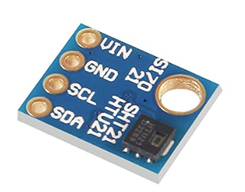
sorry, it took me a while to get back to this project as finally all parts for my slim nodes arrived and I first had to tinker with the temp sensor:) The NC door switch is working now - although I did connect the large resistor with VCC and pin and connected the switch with pin and GND. The other way around didn't seem to work for me. Here is my sketch for other people having similar issue or for comments (improvements always welcome!). /** * The MySensors Arduino library handles the wireless radio link and protocol * between your home built sensors/actuators and HA controller of choice. * The sensors forms a self healing radio network with optional repeaters. Each * repeater and gateway builds a routing tables in EEPROM which keeps track of the * network topology allowing messages to be routed to nodes. * * Created by Henrik Ekblad <henrik.ekblad@mysensors.org> * Copyright (C) 2013-2015 Sensnology AB * Full contributor list: https://github.com/mysensors/Arduino/graphs/contributors * * Documentation: http://www.mysensors.org * Support Forum: http://forum.mysensors.org * * This program is free software; you can redistribute it and/or * modify it under the terms of the GNU General Public License * version 2 as published by the Free Software Foundation. * ******************************* * * DESCRIPTION * * Simple binary switch example * Connect button or door/window reed switch between * digitial I/O pin 3 (BUTTON_PIN below) and GND. * http://www.mysensors.org/build/binary * * Connect normally closed (NC) door sensor: * VCC <--> 3.3M ohm resistor <--> pin D3 * GND <--> NC door sensor <--> pin D3 * REVISION HISTORY * v1.0: Example at https://www.mysensors.org/build/binary * v1.01: Maddhin * v1.03: first working version * */ #define SKETCH_NAME "DoorSen_NC" #define SKETCH_VERSION "1.03" //<--------- UPDATE version nummer!!! // Enable debug prints #define MY_DEBUG //<--------- switch DEBUG mode on/off // Enable REPORT_BATTERY_LEVEL to measure battery level and send changes to gateway #define REPORT_BATTERY_LEVEL // Enable and select radio type attached #define MY_RADIO_RF24 //#define MY_RADIO_RFM69 //#define MY_RS485 #define MY_NODE_ID 101 //#define MY_PARENT_NODE_ID 0 //#define MY_PARENT_NODE_IS_STATIC //#define MY_RF24_PA_LEVEL RF24_PA_MAX #include <MySensors.h> //#include <Bounce2.h> //#define CHILD_ID_HUM 0 //#define CHILD_ID_TEMP 1 #define CHILD_ID_VOLT 2 //Door sensor #define CHILD_ID_DOOR 3 #define BUTTON_PIN 3 // Arduino Digital I/O pin for button/reed switch #define ONE_DAY_SLEEP_TIME 86400000 // report battery status each day at least once //Bounce debouncer = Bounce(); int oldValue=-1; // Change to V_LIGHT if you use S_LIGHT in presentation below MyMessage msg(CHILD_ID_DOOR,V_TRIPPED); // Sleep time between sensor updates (in milliseconds) static const uint64_t UPDATE_INTERVAL = 5*60000; // x * 1 min //for debugging: //static const uint64_t UPDATE_INTERVAL = 5000; /*#include "Adafruit_HTU21DF.h" Adafruit_HTU21DF sensor = Adafruit_HTU21DF(); // Set this offset if the sensor has a permanent small offset to the real temperatures #define SENSOR_TEMP_OFFSET 0 */ #ifdef REPORT_BATTERY_LEVEL #include <Vcc.h> static uint8_t oldBatteryPcnt = 200; // Initialize to 200 to assure first time value will be sent. const float VccMin = 1.8; // Minimum expected Vcc level, in Volts: Brownout at 1.8V -> 0% const float VccMax = 2.0*1.6; // Maximum expected Vcc level, in Volts: 2xAA fresh Alkaline -> 100% const float VccCorrection = 1.0; // Measured Vcc by multimeter divided by reported Vcc static Vcc vcc(VccCorrection); #endif #ifdef MY_DEBUG #define DEBUG_PRINT(x) Serial.print (x) #define DEBUG_PRINTDEC(x) Serial.print (x, DEC) #define DEBUG_PRINTLN(x) Serial.println (x) #else #define DEBUG_PRINT(x) #define DEBUG_PRINTDEC(x) #define DEBUG_PRINTLN(x) #endif void setup() { /*// Temp Hum Sensor while (!sensor.begin()) { DEBUG_PRINTLN(F("Sensor not detected!")); while(1); delay(5000); }*/ //Door Sensor // Setup the button pinMode(BUTTON_PIN,INPUT); // Activate internal pull-up digitalWrite(BUTTON_PIN,HIGH); /*// After setting up the button, setup debouncer debouncer.attach(BUTTON_PIN); debouncer.interval(5); */ } void presentation() { // Send the sketch version information to the gateway and Controller DEBUG_PRINT("SKETCH NAME: "); DEBUG_PRINT(SKETCH_NAME); DEBUG_PRINT(", VERSION: "); DEBUG_PRINTLN(SKETCH_VERSION); sendSketchInfo(SKETCH_NAME, SKETCH_VERSION); // Present sensors as children to gateway //present(CHILD_ID_HUM, S_HUM, "Humidity"); //present(CHILD_ID_TEMP, S_TEMP, "Temperature"); present(CHILD_ID_VOLT, S_MULTIMETER, "Voltage"); // Register binary input sensor to gw (they will be created as child devices) // You can use S_DOOR, S_MOTION or S_LIGHT here depending on your usage. // If S_LIGHT is used, remember to update variable type you send in. See "msg" above. present(CHILD_ID_DOOR, S_DOOR); } void loop() { /*// Read temperature & humidity from sensor. const float temperature = float( sensor.readTemperature() ); const float humidity = float( sensor.readHumidity() ); DEBUG_PRINT(F("Temp ")); DEBUG_PRINT(temperature); DEBUG_PRINT(F("\tHum ")); DEBUG_PRINTLN(humidity); static MyMessage msgHum( CHILD_ID_HUM, V_HUM ); static MyMessage msgTemp(CHILD_ID_TEMP, V_TEMP); send(msgTemp.set(temperature, 1)); send(msgHum.set(humidity, 1)); */ //Door sensor /* debouncer.update(); // Get the update value int value = debouncer.read(); */ int value = digitalRead(BUTTON_PIN); //DEBUG_PRINT("digitalRead PIN: "); //DEBUG_PRINTLN(value); wait(50); // "debouncing" //if (value != oldValue) { if (value != oldValue) { // Send in the new value DEBUG_PRINT(F("DOOR SENSOR: ")); DEBUG_PRINTLN(value==HIGH ? 1 : 0); send(msg.set(value==HIGH ? 1 : 0)); oldValue = value; } #ifdef REPORT_BATTERY_LEVEL const uint8_t batteryPcnt = static_cast<uint8_t>(0.5 + vcc.Read_Perc(VccMin, VccMax)); static MyMessage MsgVolt(CHILD_ID_VOLT, V_VOLTAGE); // Node voltage DEBUG_PRINT(F("Vbat ")); DEBUG_PRINT(vcc.Read_Volts()); DEBUG_PRINT(F("\tPerc ")); DEBUG_PRINTLN(batteryPcnt); // Battery readout should only go down. So report only when new value is smaller than previous one. if ( batteryPcnt < oldBatteryPcnt ) { send(MsgVolt.set(vcc.Read_Volts(),2)); sendBatteryLevel(batteryPcnt); oldBatteryPcnt = batteryPcnt; } #endif // Sleep until next update to save energy //sleep(UPDATE_INTERVAL); sleep(BUTTON_PIN-2, CHANGE, ONE_DAY_SLEEP_TIME); } Now, I'll look into adding a second door switch onto the same 328P and hope I have a neat letterbox sensor up and running soon... Power consumption I will have to monitor though. But I don't really know how to measure the sleep / send current. I guess I should build some INA219 based monitor or similar. I guess, for the moment, I just "hope" the setup is good and I'll see how long the batteries will last. After running for ~24h and having triggered a bunch of times, the voltage didn't seem to have changed, so I guess that is good news... :) Thanks for your help, guys!
  • [SOLVED] s17021 vs HTU21

    temperature
    9
    1
    0 Votes
    9 Posts
    96 Views
    YveauxY
    @4994james great to hear you solved it, and thanks for reporting back!
  • HTU21D Humidity/Temperature Sensor

    8
    0 Votes
    8 Posts
    6k Views
    skywatchS
    @maddhin Any version 2 sketch with HTU21D should work as slim node is atmgea328 based. I use adafruit lib for mine and it works well. To conserve battery energy follow all the steps on the battery power page in here and send data as infrequently as you can for your needs. here is the code I use to test with - you can safely remove all the "force n updates" to reduce memory use ( I always do). It also only send if the temp or hum has changed since last reading to further reduce battery consumption.... /** * The MySensors Arduino library handles the wireless radio link and protocol * between your home built sensors/actuators and HA controller of choice. * The sensors forms a self healing radio network with optional repeaters. Each * repeater and gateway builds a routing tables in EEPROM which keeps track of the * network topology allowing messages to be routed to nodes. * * Created by Henrik Ekblad <henrik.ekblad@mysensors.org> * Copyright (C) 2013-2015 Sensnology AB * Full contributor list: https://github.com/mysensors/Arduino/graphs/contributors * * Documentation: http://www.mysensors.org * Support Forum: http://forum.mysensors.org * * This program is free software; you can redistribute it and/or * modify it under the terms of the GNU General Public License * version 2 as published by the Free Software Foundation. * ******************************* * * REVISION HISTORY * Version 1.0: Andrew Sutcliffe * * DESCRIPTION * This sketch provides an example of how to implement a humidity/temperature * sensor using a HTU21DF Sensor. * * For more information, please visit: * http://www.mysensors.org/build/humidity * * Connect Vin to 3-5VDC * Connect GND to ground * Connect SCL to I2C clock pin (A5 on UNO) * Connect SDA to I2C data pin (A4 on UNO) * */ // Enable debug prints #define MY_DEBUG // Enable and select radio type attached #define MY_RADIO_NRF24 //#define MY_RADIO_RFM69 //#define MY_RS485 #include <MySensors.h> #include <Wire.h> #include "Adafruit_HTU21DF.h" Adafruit_HTU21DF htu = Adafruit_HTU21DF(); // Set this offset if the sensor has a permanent small offset to the real temperatures #define SENSOR_TEMP_OFFSET 0 // Sleep time between sensor updates (in milliseconds) static const uint64_t UPDATE_INTERVAL = 15*60000; // Force sending an update of the temperature after n sensor reads, so a controller showing the // timestamp of the last update doesn't show something like 3 hours in the unlikely case, that // the value didn't change since; // i.e. the sensor would force sending an update every UPDATE_INTERVAL*FORCE_UPDATE_N_READS [ms] static const uint8_t FORCE_UPDATE_N_READS = 10; #define CHILD_ID_HUM 0 #define CHILD_ID_TEMP 1 float lastTemp; float lastHum; uint8_t nNoUpdatesTemp; uint8_t nNoUpdatesHum; bool metric = true; MyMessage msgHum(CHILD_ID_HUM, V_HUM); MyMessage msgTemp(CHILD_ID_TEMP, V_TEMP); void presentation() { // Send the sketch version information to the gateway sendSketchInfo("HTU21DF-TemperatureAndHumidity", "1.0"); // Register all sensors to gw (they will be created as child devices) present(CHILD_ID_HUM, S_HUM); present(CHILD_ID_TEMP, S_TEMP); } void setup() { Serial.begin(9600); Serial.println("HTU21D-F test"); if (!htu.begin()) { Serial.println("Couldn't find sensor!"); while (1); } } void loop(){ // Get temperature from HTU21DF library float temperature = (htu.readTemperature()); if (temperature != lastTemp || nNoUpdatesTemp == FORCE_UPDATE_N_READS) { // Only send temperature if it changed since the last measurement or if we didn't send an update for n times lastTemp = temperature; // Reset no updates counter nNoUpdatesTemp = 0; temperature += SENSOR_TEMP_OFFSET; send(msgTemp.set(temperature, 1)); #ifdef MY_DEBUG Serial.print("T: "); Serial.println(temperature); #endif } else { // Increase no update counter if the temperature stayed the same nNoUpdatesTemp++; } // Get humidity from HTU21DF library float humidity = (htu.readHumidity()); if (humidity != lastHum || nNoUpdatesHum == FORCE_UPDATE_N_READS) { // Only send humidity if it changed since the last measurement or if we didn't send an update for n times lastHum = humidity; // Reset no updates counter nNoUpdatesHum = 0; send(msgHum.set(humidity, 1)); #ifdef MY_DEBUG Serial.print("H: "); Serial.println(humidity); #endif } else { // Increase no update counter if the humidity stayed the same nNoUpdatesHum++; } // Sleep for a while to save energy sleep(UPDATE_INTERVAL); } Hope it helps you get up and running.
  • PCB verification request for latching valve controller

    7
    1
    0 Votes
    7 Posts
    127 Views
    W
    Hello, Thanks for all your comments!! I will implement all your improvement this weekend. I come back quickly.
  • RFM95 config for receive packet bigger than FIFO

    1
    0 Votes
    1 Posts
    20 Views
    No one has replied
  • 0 Votes
    9 Posts
    1k Views
    Nico 0N
    hi, i'm making something similar to yours, i know a lot of time has elapsed, but i'll input my knowledge. For your problem it has to do with how the data you are collecting is saved and the configuration for taking measurements you are using. You probably are using a pull measurement, instead of constant measurement. So the device will give you the data saved in register, before taking a new measurement. For example if you take a measure every 1hour, without turning off, it will give you the measurement of the preview hour each time you request for data. This is common in a lot of systems with registers. So your problem may be that when you turn on the device, there is garbage on the register. Thats why you have to do 2 measurements to get the actual value.
  • 0 Votes
    3 Posts
    908 Views
    Dennis Ng USD
    @thom4s said in [SOLVED] STM32F103C8T6 bluepill clone - RFM69HW SPI port 1 and ILI9341 SPI port 2 not working together: o myself. Problem were in wrong definition of IRQ pin in sketch. But, as I found out STM32F103C8T6 has SPI 1 running on 72MHz (for SPI max 72/2 = 36MHz) and SPI 2 36MHz (for SPI max 36/2 = 18MHz) so it were a stupid idea to wire TFT display to SPI 2 port which is slower than SPI 1 with RFM69HW which doesnt need so fast SPI. Therefore I switched radio to SPI-2 and TFT display to faster SPI-1. Radio SPI-2 and TFT ILI9341 SPI-1 wiring I'm having the same problem with NRF24L01 + ILI9341. TFT is on the SPI2 , its working but NRF24L01 on SPI1 doesnt work the moment i call tft.begin. Its not hardware related. something is wrong when i initialize the spi in the Adafruit_ILI9341_STM::begin Any thoughts?
  • New simply node sensor project - please some advise

    6
    2
    0 Votes
    6 Posts
    75 Views
    D
    Oh boys... a lot of information here. Thanks so much... but I've already place the pcb order... I have make an order for 10 pieces. :-( Bun in the mean time I'll experiment and modify the schema thanks to you all :-) Anyway I have placed there this capacitor ... I hope will be ok for this time. Thanks so much for all information Denis
  • MySensors Linky no data

    1
    0 Votes
    1 Posts
    45 Views
    No one has replied
  • Battery life calculator

    9
    1
    0 Votes
    9 Posts
    140 Views
    D
    @BearWithBeard said in Battery life calculator: you'd wake up every 30 seconds instead of once every 2 minutes. Whoawwww... I had entered wrong times :-) Now I take 409 days... great !!! Thanks a lot again Denis
  • SX 1278 LORA

    1
    0 Votes
    1 Posts
    15 Views
    No one has replied
  • What I must buy in order to measure mAh please

    12
    0 Votes
    12 Posts
    127 Views
    D
    I already have something like this, but this one have no misurement in uAh Thanks a lot Denis
  • Please give me an advice for a simple sensor node

    11
    0 Votes
    11 Posts
    106 Views
    YveauxY
    @evb said in Please give me an advice for a simple sensor node: But the node will continue to work till 1.8V in a safe operating area. Yeah sure, but alkaline batteries are nearly depleted when they get to 1V, so barely worth the hassle.
  • Heltec esp32 LoRa oled

    3
    0 Votes
    3 Posts
    902 Views
    S
    @mrussi I am also interested in using an esp32 with lora as the gateway. Did you make it work? I planning to buy, https://www.botnroll.com/en/esp/2979-esp32-wifi-bluetooth-lora-sx1278-433mhz-with-0-96-oled-display.html
  • Power management using Ebyte E32 LoRa modules

    1
    2
    0 Votes
    1 Posts
    44 Views
    No one has replied
  • Selling: Temp, Hum Si7021

    1
    2
    0 Votes
    1 Posts
    42 Views
    No one has replied

20

Online

11.7k

Users

11.2k

Topics

113.1k

Posts