Anyone using/tried the E28-2G4M27S 2.4Ghz LoRa SX1280 27dB module?
-
Good news! My PPK2 works after all. After experimenting, I determined that '"VCC" on the logic port is not a voltage source, as its name would imply. Instead, it is a voltage sense pin. So.... the way to make the logic port work is to wire the logic port VCC to the VOUT (or to whatever VCC that's powering your project). After doing so, D0 through D7 work as you would expect.
Also worthy of note: there evidently are no internal pull-up or pull-down resistors on any of the D0-D7 logic port sense pins. So, if, for example, you give D0 a high pulse and then disconnect from it, D0 will tend to stay high until it receive a low pulse.
Happy I don't need to return/exchange the PPK2 after all. :-)
-
@Larson Something I only just recently started using in the last couple of days that you may like: 0.4mm diameter Kester Rosin solder. It's ridiculously thin, but for soldering radio modules onto boards, I'm finding that I can more precisely put just enough solder exactly where I want it without having to apply solder flux to the module afterward.
-
Good news! My PPK2 works after all. After experimenting, I determined that '"VCC" on the logic port is not a voltage source, as its name would imply. Instead, it is a voltage sense pin. So.... the way to make the logic port work is to wire the logic port VCC to the VOUT (or to whatever VCC that's powering your project). After doing so, D0 through D7 work as you would expect.
Also worthy of note: there evidently are no internal pull-up or pull-down resistors on any of the D0-D7 logic port sense pins. So, if, for example, you give D0 a high pulse and then disconnect from it, D0 will tend to stay high until it receive a low pulse.
Happy I don't need to return/exchange the PPK2 after all. :-)
@NeverDie said in Anyone using/tried the E28-2G4M27S 2.4Ghz LoRa SX1280 27dB module?:
Glad to hear you solved it. I was hoping to help you, for a change. You are too fast for me. I just got home from a grueling day.
So, if, for example, you give D0 a high pulse and then disconnect from it, D0 will tend to stay high until it receive a low pulse.
By 'disconnect' do you mean sleeping? It sounds like Pull-Up/Down on the DUT pin would solve it. Ohhh, I'm thinking that disconnect means when the MCU disengages the PPKII. Or perhaps VCC pin is at play. I know so little of the PPKII, but I would imagine it couldn't have any Pull-Up/Down assignments or it would be fighting the DUT Pull direction. The result of double pulls would be a voltage divider and give some misleading indications.
-
@NeverDie said in Anyone using/tried the E28-2G4M27S 2.4Ghz LoRa SX1280 27dB module?:
Glad to hear you solved it. I was hoping to help you, for a change. You are too fast for me. I just got home from a grueling day.
So, if, for example, you give D0 a high pulse and then disconnect from it, D0 will tend to stay high until it receive a low pulse.
By 'disconnect' do you mean sleeping? It sounds like Pull-Up/Down on the DUT pin would solve it. Ohhh, I'm thinking that disconnect means when the MCU disengages the PPKII. Or perhaps VCC pin is at play. I know so little of the PPKII, but I would imagine it couldn't have any Pull-Up/Down assignments or it would be fighting the DUT Pull direction. The result of double pulls would be a voltage divider and give some misleading indications.
@Larson said in Anyone using/tried the E28-2G4M27S 2.4Ghz LoRa SX1280 27dB module?:
@NeverDie said in Anyone using/tried the E28-2G4M27S 2.4Ghz LoRa SX1280 27dB module?:
Glad to hear you solved it. I was hoping to help you, for a change. You are too fast for me. I just got home from a grueling day.
So, if, for example, you give D0 a high pulse and then disconnect from it, D0 will tend to stay high until it receive a low pulse.
By 'disconnect' do you mean sleeping? It sounds like Pull-Up/Down on the DUT pin would solve it. Ohhh, I'm thinking that disconnect means when the MCU disengages the PPKII. Or perhaps VCC pin is at play. I know so little of the PPKII, but I would imagine it couldn't have any Pull-Up/Down assignments or it would be fighting the DUT Pull direction. The result of double pulls would be a voltage divider and give some misleading indications.
By disconnect I just mean, for example, taking a wire that's connected to D0 and touching it to GND and then pulling the wire away so that it's no longer touching GND. It's not something you would do "in real life," but I was doing it just to confirm that the PPK2 was working.
-
@Larson Something I only just recently started using in the last couple of days that you may like: 0.4mm diameter Kester Rosin solder. It's ridiculously thin, but for soldering radio modules onto boards, I'm finding that I can more precisely put just enough solder exactly where I want it without having to apply solder flux to the module afterward.
@NeverDie said in Anyone using/tried the E28-2G4M27S 2.4Ghz LoRa SX1280 27dB module?:
0.4mm diameter Kester Rosin solder.
I'll put it on my list. After the Male/Female antennae discussion above, I'm sure I got my order wrong - so I'll have a new running list shortly when everything arrives. I checked my solder with a caliper since the dimensions are listed in Chinese: it is 0.6 mm so I'm not far away. I do like the feel the smaller diameter has in comparison to my larger solder so I'm sure 0.4 mm will even be better.
-
@NeverDie said in Anyone using/tried the E28-2G4M27S 2.4Ghz LoRa SX1280 27dB module?:
0.4mm diameter Kester Rosin solder.
I'll put it on my list. After the Male/Female antennae discussion above, I'm sure I got my order wrong - so I'll have a new running list shortly when everything arrives. I checked my solder with a caliper since the dimensions are listed in Chinese: it is 0.6 mm so I'm not far away. I do like the feel the smaller diameter has in comparison to my larger solder so I'm sure 0.4 mm will even be better.
@Larson said in Anyone using/tried the E28-2G4M27S 2.4Ghz LoRa SX1280 27dB module?:
@NeverDie said in Anyone using/tried the E28-2G4M27S 2.4Ghz LoRa SX1280 27dB module?:
0.4mm diameter Kester Rosin solder.
I'll put it on my list. After the Male/Female antennae discussion above, I'm sure I got my order wrong - so I'll have a new running list shortly when everything arrives. I checked my solder with a caliper since the dimensions are listed in Chinese: it is 0.6 mm so I'm not far away. I do like the feel the smaller diameter has in comparison to my larger solder so I'm sure 0.4 mm will even be better.
Yeah, I was using 0.635mm MG Chemicals solder previously, but I found I had to drown the radio modules in rosin flux afterward to eliminate solder bridges, etc. Perhaps part of the difference may be that Kester uses a different formulation for its in-line flux than MG Chemicals? I suppose that could also have something to do with it. So, maybe it's not entirely diameter, but having now worked with the two different diameters, my gut intuition is that the smaller diameter is helping.
Anyone else reading this having any opinions on the matter that they are willing to share?
-
@NeverDie said in Anyone using/tried the E28-2G4M27S 2.4Ghz LoRa SX1280 27dB module?:
0.4mm diameter Kester Rosin solder.
I'll put it on my list. After the Male/Female antennae discussion above, I'm sure I got my order wrong - so I'll have a new running list shortly when everything arrives. I checked my solder with a caliper since the dimensions are listed in Chinese: it is 0.6 mm so I'm not far away. I do like the feel the smaller diameter has in comparison to my larger solder so I'm sure 0.4 mm will even be better.
@Larson said in Anyone using/tried the E28-2G4M27S 2.4Ghz LoRa SX1280 27dB module?:
I checked my solder with a caliper since the dimensions are listed in Chinese: it is 0.6 mm so I'm not far away.
Ha, I just did the simple math. Since the cross-sectional area is function of the squared radius, 0.4 is vastly different (better?) than the 0.6 mm. The 0.4 mm will feed 2.25 times as fast as the 0.6 mm for the same volume - maybe even more if there is a higher evaporative flux component. That is a big difference.
-
@Larson said in Anyone using/tried the E28-2G4M27S 2.4Ghz LoRa SX1280 27dB module?:
@NeverDie said in Anyone using/tried the E28-2G4M27S 2.4Ghz LoRa SX1280 27dB module?:
0.4mm diameter Kester Rosin solder.
I'll put it on my list. After the Male/Female antennae discussion above, I'm sure I got my order wrong - so I'll have a new running list shortly when everything arrives. I checked my solder with a caliper since the dimensions are listed in Chinese: it is 0.6 mm so I'm not far away. I do like the feel the smaller diameter has in comparison to my larger solder so I'm sure 0.4 mm will even be better.
Yeah, I was using 0.635mm MG Chemicals solder previously, but I found I had to drown the radio modules in rosin flux afterward to eliminate solder bridges, etc. Perhaps part of the difference may be that Kester uses a different formulation for its in-line flux than MG Chemicals? I suppose that could also have something to do with it. So, maybe it's not entirely diameter, but having now worked with the two different diameters, my gut intuition is that the smaller diameter is helping.
Anyone else reading this having any opinions on the matter that they are willing to share?
@NeverDie said in Anyone using/tried the E28-2G4M27S 2.4Ghz LoRa SX1280 27dB module?:
Anyone else reading this having any opinions on the matter that they are willing to share?
I'm sure there are. Initially, I was not only occasional but also reluctant to comment due to my lack of credible contribution. You helped me overcome that. This thread will be a resource for a multitude of others that will be too late for contemporary comment. Keep on going, man.
Today's achievement for me: PPK2 software is loaded (not that simple) and it is funcitoning. Super cool metrics. I'll shortly post my crystal/non-crystal measurements for my own enjoyment.
-
@Larson said in Anyone using/tried the E28-2G4M27S 2.4Ghz LoRa SX1280 27dB module?:
@NeverDie said in Anyone using/tried the E28-2G4M27S 2.4Ghz LoRa SX1280 27dB module?:
0.4mm diameter Kester Rosin solder.
I'll put it on my list. After the Male/Female antennae discussion above, I'm sure I got my order wrong - so I'll have a new running list shortly when everything arrives. I checked my solder with a caliper since the dimensions are listed in Chinese: it is 0.6 mm so I'm not far away. I do like the feel the smaller diameter has in comparison to my larger solder so I'm sure 0.4 mm will even be better.
Yeah, I was using 0.635mm MG Chemicals solder previously, but I found I had to drown the radio modules in rosin flux afterward to eliminate solder bridges, etc. Perhaps part of the difference may be that Kester uses a different formulation for its in-line flux than MG Chemicals? I suppose that could also have something to do with it. So, maybe it's not entirely diameter, but having now worked with the two different diameters, my gut intuition is that the smaller diameter is helping.
Anyone else reading this having any opinions on the matter that they are willing to share?
@NeverDie said in Anyone using/tried the E28-2G4M27S 2.4Ghz LoRa SX1280 27dB module?:
@Larson said in Anyone using/tried the E28-2G4M27S 2.4Ghz LoRa SX1280 27dB module?:
@NeverDie said in Anyone using/tried the E28-2G4M27S 2.4Ghz LoRa SX1280 27dB module?:
0.4mm diameter Kester Rosin solder.
I'll put it on my list. After the Male/Female antennae discussion above, I'm sure I got my order wrong - so I'll have a new running list shortly when everything arrives. I checked my solder with a caliper since the dimensions are listed in Chinese: it is 0.6 mm so I'm not far away. I do like the feel the smaller diameter has in comparison to my larger solder so I'm sure 0.4 mm will even be better.
Yeah, I was using 0.635mm MG Chemicals solder previously, but I found I had to drown the radio modules in rosin flux afterward to eliminate solder bridges, etc. Perhaps part of the difference may be that Kester uses a different formulation for its in-line flux than MG Chemicals? I suppose that could also have something to do with it. So, maybe it's not entirely diameter, but having now worked with the two different diameters, my gut intuition is that the smaller diameter is helping.
Anyone else reading this having any opinions on the matter that they are willing to share?
I swear by the stuff in the picture below. It melts at a lower temperature(179 C) so, as an amateur, I feel safer keeping my iron at a lower temp and in place a little longer when I am working with IC's. I like that it's thin too as it is easier to control how much you apply. I have no issues with it, it flows well and doesn't create bridges (unless I use too much).
-
@NeverDie said in Anyone using/tried the E28-2G4M27S 2.4Ghz LoRa SX1280 27dB module?:
@Larson said in Anyone using/tried the E28-2G4M27S 2.4Ghz LoRa SX1280 27dB module?:
@NeverDie said in Anyone using/tried the E28-2G4M27S 2.4Ghz LoRa SX1280 27dB module?:
0.4mm diameter Kester Rosin solder.
I'll put it on my list. After the Male/Female antennae discussion above, I'm sure I got my order wrong - so I'll have a new running list shortly when everything arrives. I checked my solder with a caliper since the dimensions are listed in Chinese: it is 0.6 mm so I'm not far away. I do like the feel the smaller diameter has in comparison to my larger solder so I'm sure 0.4 mm will even be better.
Yeah, I was using 0.635mm MG Chemicals solder previously, but I found I had to drown the radio modules in rosin flux afterward to eliminate solder bridges, etc. Perhaps part of the difference may be that Kester uses a different formulation for its in-line flux than MG Chemicals? I suppose that could also have something to do with it. So, maybe it's not entirely diameter, but having now worked with the two different diameters, my gut intuition is that the smaller diameter is helping.
Anyone else reading this having any opinions on the matter that they are willing to share?
I swear by the stuff in the picture below. It melts at a lower temperature(179 C) so, as an amateur, I feel safer keeping my iron at a lower temp and in place a little longer when I am working with IC's. I like that it's thin too as it is easier to control how much you apply. I have no issues with it, it flows well and doesn't create bridges (unless I use too much).
@alphaHotel Thanks for the tip! I added it to my mouser shopping basket.
Like Dave from EEVblog I tend to run my soldering pencil hotter than I should but work quickly to compensate, so maybe with this Chipquik solder I can dial it down. For sure the Chipquik desoldering solder works extremely well.
-
@NeverDie said in Anyone using/tried the E28-2G4M27S 2.4Ghz LoRa SX1280 27dB module?:
@Larson said in Anyone using/tried the E28-2G4M27S 2.4Ghz LoRa SX1280 27dB module?:
@NeverDie said in Anyone using/tried the E28-2G4M27S 2.4Ghz LoRa SX1280 27dB module?:
0.4mm diameter Kester Rosin solder.
I'll put it on my list. After the Male/Female antennae discussion above, I'm sure I got my order wrong - so I'll have a new running list shortly when everything arrives. I checked my solder with a caliper since the dimensions are listed in Chinese: it is 0.6 mm so I'm not far away. I do like the feel the smaller diameter has in comparison to my larger solder so I'm sure 0.4 mm will even be better.
Yeah, I was using 0.635mm MG Chemicals solder previously, but I found I had to drown the radio modules in rosin flux afterward to eliminate solder bridges, etc. Perhaps part of the difference may be that Kester uses a different formulation for its in-line flux than MG Chemicals? I suppose that could also have something to do with it. So, maybe it's not entirely diameter, but having now worked with the two different diameters, my gut intuition is that the smaller diameter is helping.
Anyone else reading this having any opinions on the matter that they are willing to share?
I swear by the stuff in the picture below. It melts at a lower temperature(179 C) so, as an amateur, I feel safer keeping my iron at a lower temp and in place a little longer when I am working with IC's. I like that it's thin too as it is easier to control how much you apply. I have no issues with it, it flows well and doesn't create bridges (unless I use too much).
@alphaHotel & @NeverDie: My ChipQuik kit arrived as did the SRA flux. Look forward to working with it. I find the "No-Clean" claim concerning but I am armed with my new 99% alcohol just in case.
@NeverDie: The PPK2 is great. I did a few tests and captures today - no logic-port evaluation yet. It will take me another day to learn the fuse settings. Yes, Gammon is the master of the fuse subject as I learned with PIC chips. More on PPK2: I’m using the LowPower library (Felix R. I think). After sleep, the PPK tells me that the current is 4 uA. Zeesh, with the 18650 LiOn battery decay rate of 28’ish uA, I’m not sure if I need fuse settings. Well, there is the optimization of the thing, so I will press on. -
@alphaHotel & @NeverDie: My ChipQuik kit arrived as did the SRA flux. Look forward to working with it. I find the "No-Clean" claim concerning but I am armed with my new 99% alcohol just in case.
@NeverDie: The PPK2 is great. I did a few tests and captures today - no logic-port evaluation yet. It will take me another day to learn the fuse settings. Yes, Gammon is the master of the fuse subject as I learned with PIC chips. More on PPK2: I’m using the LowPower library (Felix R. I think). After sleep, the PPK tells me that the current is 4 uA. Zeesh, with the 18650 LiOn battery decay rate of 28’ish uA, I’m not sure if I need fuse settings. Well, there is the optimization of the thing, so I will press on.@Larson Yeah, I think of "No Clean" as really being "easier to clean." There's still some residue with those that I have tried, but they really are easier to clean up after than the regular flux.
So I still prefer them, but I don't like to leave them uncleaned. Maybe the residue isn't corrosive like regular flux? At any rate I don't trust it either.
-
@Larson Here's all you need to know in one place on how to get to 100na sleep current on the atmega328p: https://www.gammon.com.au/power He covers all the different methods. TL;DR: burn your fuses to:
External: 0xFF
High: 0xDC
Low: 0xC2
and then run Sketch J from the Nick Gammon link. That's all there is to it, provided you have an external device/circuit to wake up your atmega328p.@NeverDie said in Anyone using/tried the E28-2G4M27S 2.4Ghz LoRa SX1280 27dB module?:
@Larson Here's all you need to know in one place on how to get to 100na sleep current on the atmega328p: https://www.gammon.com.au/power He covers all the different methods. TL;DR: burn your fuses to:
External: 0xFF
High: 0xDC
Low: 0xC2
and then run Sketch J from the Nick Gammon link. That's all there is to it, provided you have an external device/circuit to wake up your atmega328p.It sounded so simple. Today I gave it a shot. The fuse setting is just like I remembered it: complicated. The bottom line is that, using Sketch J, I am able to get down to 0.25 uA even without changing fuses. Not that I didn’t try to change fuses. I got out my USBASP and have been bootloading and fuse-setting all day. I used avrdude and had trouble getting the commands to work right (conf file directory must be specified.) I tried your recommended fuse settings but then couldn’t upload programs. So, I changed back to default fuse settings and still couldn’t upload programs. Seems to be that another bootloader reset got me back to normal. So… if I can get to 0.25 uA, I’m super happy. The additional 0.1 uA reduction is just too difficult for me. I'm not exactly sure how this helps in the radio stuff, but it has been a really good excercise of my new PPK2 device. I am very impressed.
I’m kind of shocked that the PPK2 has that granularity. As Gammon indicated with Sketch J, I could ground D2 (INT0) to cause an interrupt to blink the LED. That on its own is a valuable tool. Here is a picture. Thanks for holding my hand in this stuff – it has been most helpful.
-
@Larson Something I only just recently started using in the last couple of days that you may like: 0.4mm diameter Kester Rosin solder. It's ridiculously thin, but for soldering radio modules onto boards, I'm finding that I can more precisely put just enough solder exactly where I want it without having to apply solder flux to the module afterward.
@NeverDie said in Anyone using/tried the E28-2G4M27S 2.4Ghz LoRa SX1280 27dB module?:
Something I only just recently started using in the last couple of days that you may like: 0.4mm diameter Kester Rosin solder. It's ridiculously thin, but for soldering radio modules onto boards, I'm finding that I can more precisely put just enough solder exactly where I want it without having to apply solder flux to the module afterward.
I'm out shoping for this solder. I can find this 20 mil solder, but not the 0.4 mm (16 mil) stuff. Do you have a link?
-
@NeverDie said in Anyone using/tried the E28-2G4M27S 2.4Ghz LoRa SX1280 27dB module?:
@Larson said in Anyone using/tried the E28-2G4M27S 2.4Ghz LoRa SX1280 27dB module?:
@NeverDie said in Anyone using/tried the E28-2G4M27S 2.4Ghz LoRa SX1280 27dB module?:
0.4mm diameter Kester Rosin solder.
I'll put it on my list. After the Male/Female antennae discussion above, I'm sure I got my order wrong - so I'll have a new running list shortly when everything arrives. I checked my solder with a caliper since the dimensions are listed in Chinese: it is 0.6 mm so I'm not far away. I do like the feel the smaller diameter has in comparison to my larger solder so I'm sure 0.4 mm will even be better.
Yeah, I was using 0.635mm MG Chemicals solder previously, but I found I had to drown the radio modules in rosin flux afterward to eliminate solder bridges, etc. Perhaps part of the difference may be that Kester uses a different formulation for its in-line flux than MG Chemicals? I suppose that could also have something to do with it. So, maybe it's not entirely diameter, but having now worked with the two different diameters, my gut intuition is that the smaller diameter is helping.
Anyone else reading this having any opinions on the matter that they are willing to share?
I swear by the stuff in the picture below. It melts at a lower temperature(179 C) so, as an amateur, I feel safer keeping my iron at a lower temp and in place a little longer when I am working with IC's. I like that it's thin too as it is easier to control how much you apply. I have no issues with it, it flows well and doesn't create bridges (unless I use too much).
@alphaHotel said in Anyone using/tried the E28-2G4M27S 2.4Ghz LoRa SX1280 27dB module?:
I swear by the stuff in the picture below. It melts at a lower temperature(179 C) so, as an amateur, I feel safer keeping my iron at a lower temp and in place a little longer when I am working with IC's. I like that it's thin too as it is easier to control how much you apply. I have no issues with it, it flows well and doesn't create bridges (unless I use too much).
On your recommendation I'm looking for this solder as well. For those who follow this thread I found it here.
The solder diameter that came with my Chipquick SMD1 Removal kit was enough for one job, maybe. The linked 4 Oz. supply will last some time for me.
-
@NeverDie said in Anyone using/tried the E28-2G4M27S 2.4Ghz LoRa SX1280 27dB module?:
Something I only just recently started using in the last couple of days that you may like: 0.4mm diameter Kester Rosin solder. It's ridiculously thin, but for soldering radio modules onto boards, I'm finding that I can more precisely put just enough solder exactly where I want it without having to apply solder flux to the module afterward.
I'm out shoping for this solder. I can find this 20 mil solder, but not the 0.4 mm (16 mil) stuff. Do you have a link?
@Larson said in Anyone using/tried the E28-2G4M27S 2.4Ghz LoRa SX1280 27dB module?:
I'm out shoping for this solder. I can find this 20 mil solder, but not the 0.4 mm (16 mil) stuff. Do you have a link?
It is Kester 24-6337-0007 https://www.amazon.com/KESTER-SOLDER-24-6337-0007-WIRE-183°C/dp/B00DDDHF2W/ref=sr_1_2?keywords=Kester+24-6337-0007&qid=1655879942&sr=8-2 That's half the price that mouser would charge for the exact same thing. Go figure.
-
@alphaHotel said in Anyone using/tried the E28-2G4M27S 2.4Ghz LoRa SX1280 27dB module?:
I swear by the stuff in the picture below. It melts at a lower temperature(179 C) so, as an amateur, I feel safer keeping my iron at a lower temp and in place a little longer when I am working with IC's. I like that it's thin too as it is easier to control how much you apply. I have no issues with it, it flows well and doesn't create bridges (unless I use too much).
On your recommendation I'm looking for this solder as well. For those who follow this thread I found it here.
The solder diameter that came with my Chipquick SMD1 Removal kit was enough for one job, maybe. The linked 4 Oz. supply will last some time for me.
@Larson said in Anyone using/tried the E28-2G4M27S 2.4Ghz LoRa SX1280 27dB module?:
On your recommendation I'm looking for this solder as well. For those who follow this thread I found it here.
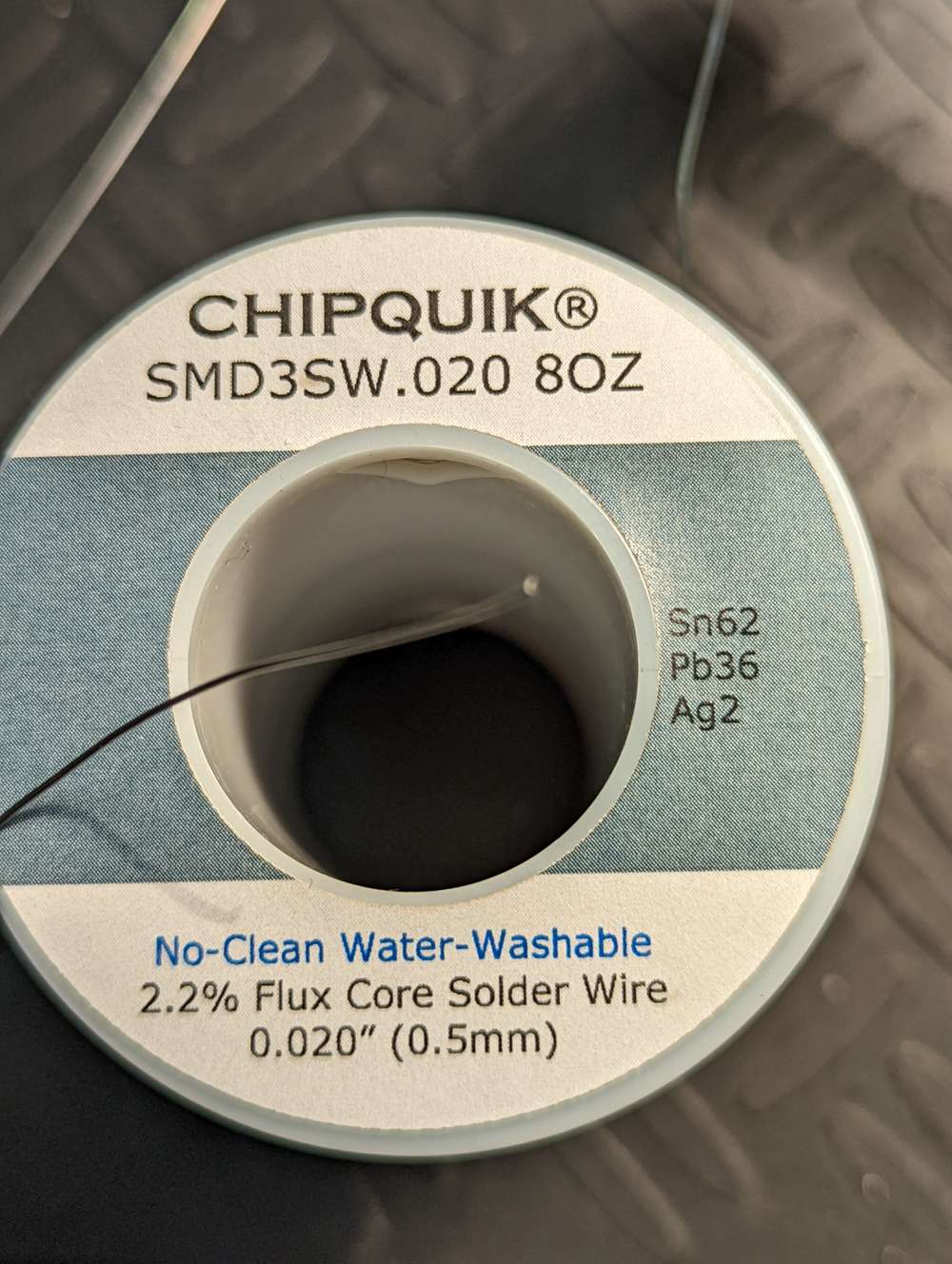
The solder diameter that came with my Chipquick SMD1 Removal kit was enough for one job, maybe. The linked 4 Oz. supply will last some time for me.That's not quite the same stuff. What I use has a small amount of silver content in the alloy. You can find it here at Mouser.com. The smallest size they have though is the 8oz which is basically, a lifetime supply for me at least.
-
@Larson said in Anyone using/tried the E28-2G4M27S 2.4Ghz LoRa SX1280 27dB module?:
I'm out shoping for this solder. I can find this 20 mil solder, but not the 0.4 mm (16 mil) stuff. Do you have a link?
It is Kester 24-6337-0007 https://www.amazon.com/KESTER-SOLDER-24-6337-0007-WIRE-183°C/dp/B00DDDHF2W/ref=sr_1_2?keywords=Kester+24-6337-0007&qid=1655879942&sr=8-2 That's half the price that mouser would charge for the exact same thing. Go figure.
@NeverDie and
@alphaHotelThanks for the links. I'm going for the silver (Ag)! The little that I remember from physics is that silver has high conductivity and low melting point. Perfect. Too bad it is so expensive.
I have a few dental crowns that could be remelted and ...
-
@Larson said in Anyone using/tried the E28-2G4M27S 2.4Ghz LoRa SX1280 27dB module?:
@NeverDie said in Anyone using/tried the E28-2G4M27S 2.4Ghz LoRa SX1280 27dB module?:
In its favor is that at 40na the sleep current...
I'll order several. Then compare to the TrigBoards. Adafruit's TPL5011 advertises a run current of 20uA. Is that acceptable for you? If so I'll buy several. Couple of limitations for me: 1. Time - I'm about a month out, 2. My Ammeter is a standard DMM from Harbor Freight. The smallest range is 200uA and I've found it very useful. Certainly fine enough to show the 20uA, but inadequate for nanoAmps.
Hmmmm... Something's wrong then with Adafruit's design if it's 20uA. The chip itself consumes only 35na according to its datasheet:
https://www.ti.com/lit/ds/symlink/tpl5110.pdf?ts=1652658923819&ref_url=https%253A%252F%252Fwww.google.com%252F
Maybe their p-channel mosfet has high leakage current with the circuit has they've designed it? I would pass if it really is 20uA. I'm sure I could do better than that.You need something like either a Current Ranger or a MicroCurrent Gold to accurately measure microamps and nanoamps. Cost is around $100.
Also, I just now looked at one of Kevin Darrah's videos:
https://www.youtube.com/watch?v=WNH6tyQpwF4where he has embraced ESP-NOW. He said his esp8266 still takes around 1.5 seconds to wake up and transmit, even though running ESP-NOW, which is a very long time, as the module will be burning current through out that wake-up interval. In the example he showed, the delay was quite noticeable (though definitely an improvement compared to before when he was using plain wi-fi). Of course, the devil is in the details, but seeing that I'm more skeptical now than before.
From the MySensors forum entry:
@NeverDie said in Anyone using/tried the E28-2G4M27S 2.4Ghz LoRa SX1280 27dB module?:
Hmmmm... Something's wrong then with Adafruit's design if it's 20uA. The chip itself consumes only 35na according to its datasheet:
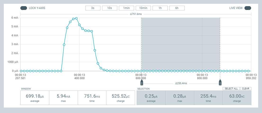
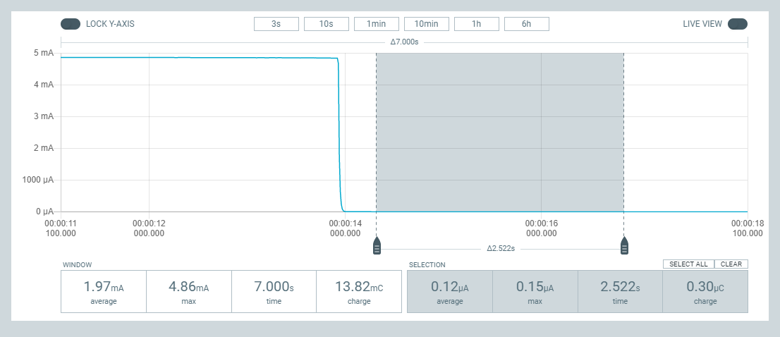
https://www.ti.com/lit/ds/symlink/tpl5110.pdf?ts=1652658923819&ref_url=https%3A%2F%2Fwww.google.com%2FMy TPL5110's arrived and I hooked one up to the PPKII to take a look. Remember that Adafruit advertised a disappointing OFF-state current of 20 uA. Fortunately, I have found this not to be the case. Instead, my PPKII shows the off state to be 120 nA; picture attached. The load I used was an LED hooked up to a resistor and the PPK is supplied with 3.3V. As earlier discussed, I’ll next dig out the TrigBoards that Kevin Darrah sent me to see how they do.
-
From the MySensors forum entry:
@NeverDie said in Anyone using/tried the E28-2G4M27S 2.4Ghz LoRa SX1280 27dB module?:
Hmmmm... Something's wrong then with Adafruit's design if it's 20uA. The chip itself consumes only 35na according to its datasheet:
https://www.ti.com/lit/ds/symlink/tpl5110.pdf?ts=1652658923819&ref_url=https%3A%2F%2Fwww.google.com%2FMy TPL5110's arrived and I hooked one up to the PPKII to take a look. Remember that Adafruit advertised a disappointing OFF-state current of 20 uA. Fortunately, I have found this not to be the case. Instead, my PPKII shows the off state to be 120 nA; picture attached. The load I used was an LED hooked up to a resistor and the PPK is supplied with 3.3V. As earlier discussed, I’ll next dig out the TrigBoards that Kevin Darrah sent me to see how they do.
@Larson Thanks for posting your measurements. Mine match up with yours: https://forum.mysensors.org/topic/11954/most-reliable-best-radio/20?_=1656174349755
I just yesterday put together a TPL5111 to serve as purely a wake-up timer for a sleeping MCU, and it's working well also in that capacity.
Hello! It looks like you're interested in this conversation, but you don't have an account yet.
Getting fed up of having to scroll through the same posts each visit? When you register for an account, you'll always come back to exactly where you were before, and choose to be notified of new replies (either via email, or push notification). You'll also be able to save bookmarks and upvote posts to show your appreciation to other community members.
With your input, this post could be even better 💗
Register Login