Mailbox/Postbox Alert
-
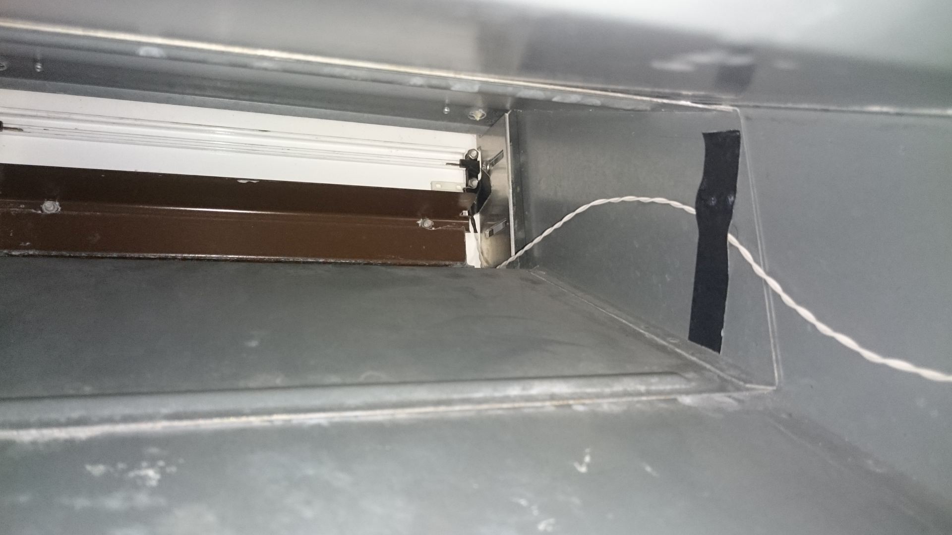
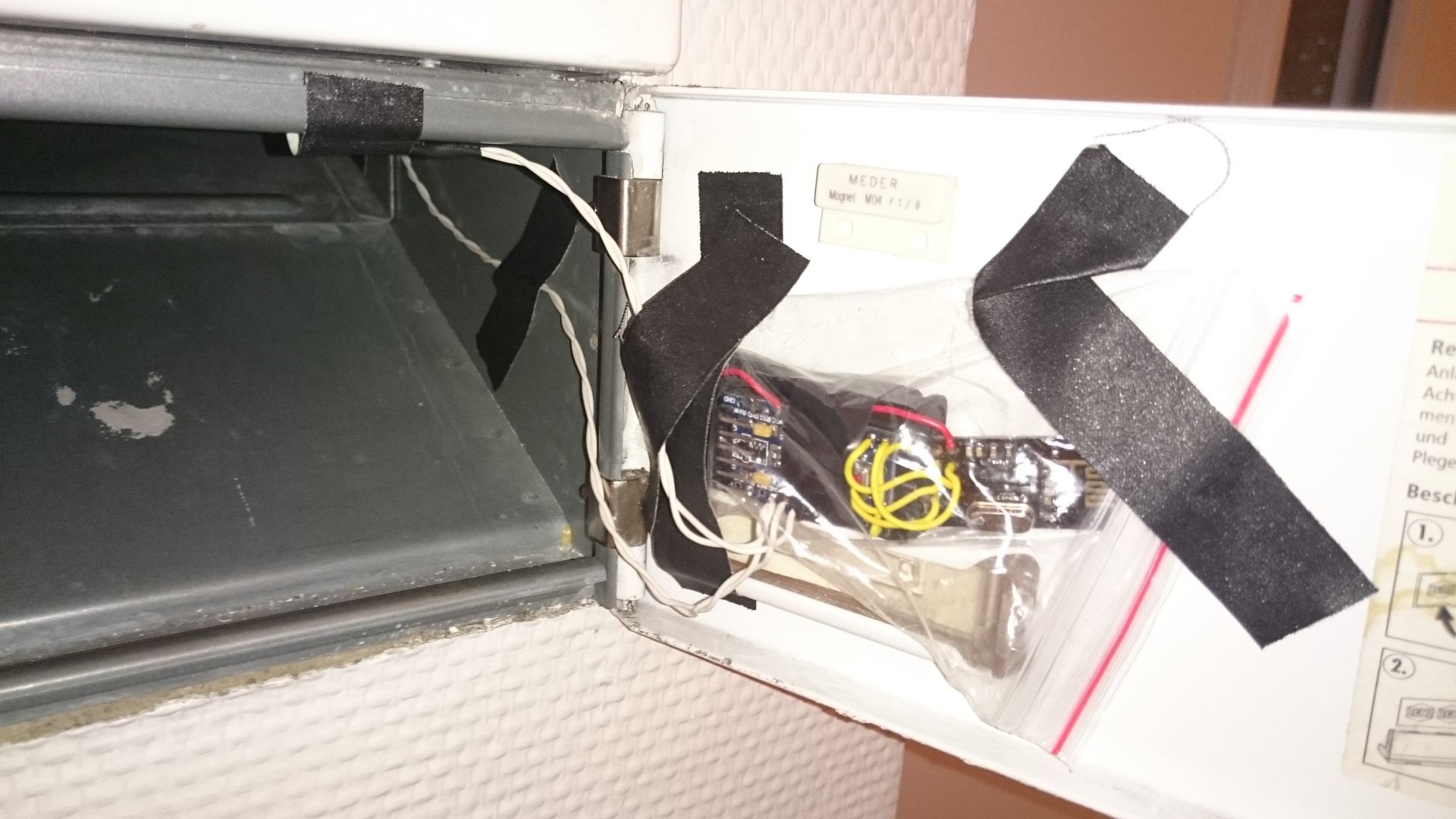
Just finished my new project.
I have added two magnetic switches to the front and the back of my postbox. Now i get a Mail if the postman was here :)
You need:
1x Arduino Mini Pro 3,3
1x Battery Holder (2xaaa)
1x NRF
2x Reed switches (http://www.reichelt.de/KSK-1A663-2025/3/index.html?&ACTION=3&LA=446&ARTICLE=151700&artnr=KSK+1A663+2025&SEARCH=magnet+schlie�er)
2x magnets (http://www.reichelt.de/MAGNET-M4/3/index.html?&ACTION=3&LA=446&ARTICLE=12483&artnr=MAGNET+M4&SEARCH=magnet)And this or a similar sketch: https://github.com/n3roGit/MySensors_n3ro/tree/master/Mailbox_Alert
It works great =)
@n3ro said:
2x Reedschalter (http://www.reichelt.de/KSK-1A663-2025/3/index.html?&ACTION=3&LA=446&ARTICLE=151700&artnr=KSK+1A663+2025&SEARCH=magnet+schlie�er)
Hast du gut gemacht mit dem Reedschalter.:stuck_out_tongue_closed_eyes:
I mean nice denglish :grin:
-
@n3ro said:
2x Reedschalter (http://www.reichelt.de/KSK-1A663-2025/3/index.html?&ACTION=3&LA=446&ARTICLE=151700&artnr=KSK+1A663+2025&SEARCH=magnet+schlie�er)
Hast du gut gemacht mit dem Reedschalter.:stuck_out_tongue_closed_eyes:
I mean nice denglish :grin:
-
Just finished my new project.
I have added two magnetic switches to the front and the back of my postbox. Now i get a Mail if the postman was here :)
You need:
1x Arduino Mini Pro 3,3
1x Battery Holder (2xaaa)
1x NRF
2x Reed switches (http://www.reichelt.de/KSK-1A663-2025/3/index.html?&ACTION=3&LA=446&ARTICLE=151700&artnr=KSK+1A663+2025&SEARCH=magnet+schlie�er)
2x magnets (http://www.reichelt.de/MAGNET-M4/3/index.html?&ACTION=3&LA=446&ARTICLE=12483&artnr=MAGNET+M4&SEARCH=magnet)And this or a similar sketch: https://github.com/n3roGit/MySensors_n3ro/tree/master/Mailbox_Alert
It works great =)
@n3ro I wish mine had a flap... still trying to figure out a way to do that
-
hmm after some days testing it works very fine, but:
the battery drains very fast and in dont know why. The Arduino sleeps the whole time and wakes up when the postman is coming (maybe 2 times a week).
The battery drains 11% in 7 Days :(
Any Ideas?
The power LED and regulator is cutted and the fuses are modified.
Regards
n3ro -
I'm guessing that your repeat() function is wearing out the battery.
By the way you can take advantage of the return of sleep( ) here:
gw.sleep(MAILBOX_FRONT_PIN - 2, CHANGE, MAILBOX_BACK_PIN - 2, CHANGE, 0);like this (untested):
#include <MySensor.h> #include <SPI.h> #include <readVcc.h> #define NODE_ID 21 // ID of node #define CHILD_ID 1 // Id of the sensor child #define MAILBOX_FRONT_PIN 2 // Arduino Digital I/O pin for button/reed switch #define MAILBOX_BACK_PIN 3 // Arduino Digital I/O pin for button/reed switch #define MIN_V 1900 // empty voltage (0%) #define MAX_V 3200 // full voltage (100%) MySensor gw; MyMessage msg(CHILD_ID, V_TRIPPED); boolean post = false; boolean lastpost = false; int oldBatteryPcnt; int repeat = 20; int trigger = -1; unsigned long goToSleepTime; void setup() { gw.begin(NULL, NODE_ID, false); pinMode(MAILBOX_FRONT_PIN, INPUT); pinMode(MAILBOX_BACK_PIN, INPUT); digitalWrite(MAILBOX_FRONT_PIN, HIGH); digitalWrite(MAILBOX_BACK_PIN, HIGH); gw.sendSketchInfo("Mailbox Alert", "1.0"); gw.present(CHILD_ID, S_MOTION); Serial.println("---------- set Mailbox empty"); msg.set(0); } void loop() { if (millis() - goToSleepTime > 10UL) //debounce { switch (trigger) { case 0: post = true; Serial.println("---------- New Mail"); break; case 1: post = false; Serial.println("---------- Mailbox emptied"); break; default: Serial.println("---------- I just woke up"); } } trigger = -1; if (post != lastpost) { Serial.print("---------- Send Mailboxstate "); Serial.println(post ? "full" : "empty"); msg.set(post); lastpost = post; sendBattery(); } // Sleep until something happens with the sensor goToSleepTime = millis(); trigger = gw.sleep(MAILBOX_FRONT_PIN - 2, CHANGE, MAILBOX_BACK_PIN - 2, CHANGE, 0); } void sendBattery() // Measure battery { int batteryPcnt = min(map(readVcc(), MIN_V, MAX_V, 0, 100), 100); if (batteryPcnt != oldBatteryPcnt) { gw.sendBatteryLevel(batteryPcnt); // Send battery percentage oldBatteryPcnt = batteryPcnt; } Serial.print("---------- Battery: "); Serial.println(batteryPcnt); } -
-
it is fixed :) changed internal pullup to an external with 680k. now its 32uA with both opened and 47uA with both closed :)
@n3ro how do you do that?
-
Hi!
I+m trying to do a similar mailbox sensor, but I get different power consumptions hen I ground (pulling down) input pin 2 and 3.I´m using a pro mini, 3.3v standard boot loader with removed LED and 470k resistors as external pull-ups.
In sleep mode with it draws about 65uA
Roughly the same with input pin 3 -grounded (state 0)
But when I ground pin 2 it draws 7mAAny ideas whats wrong?
-
@n3ro how do you do that?
@Moshe-Livne just deactivate the this lines:
//digitalWrite(MAILBOX_FRONT_PIN, HIGH);
//digitalWrite(MAILBOX_BACK_PIN, HIGH);and solder two resistor from 3.3v to pin 2 and 3.
-
@Moshe-Livne just deactivate the this lines:
//digitalWrite(MAILBOX_FRONT_PIN, HIGH);
//digitalWrite(MAILBOX_BACK_PIN, HIGH);and solder two resistor from 3.3v to pin 2 and 3.
Ok, so I found that it is the radio that draws about 7mA when I ground input pin 2, it is connected to IRQ-pin on the radio.
@n3ro Have you connected the radio as described on the build-page? [http://www.mysensors.org/build/connect_radio](link url) -
Ok, so I found that it is the radio that draws about 7mA when I ground input pin 2, it is connected to IRQ-pin on the radio.
@n3ro Have you connected the radio as described on the build-page? [http://www.mysensors.org/build/connect_radio](link url) -
I'm guessing that your repeat() function is wearing out the battery.
By the way you can take advantage of the return of sleep( ) here:
gw.sleep(MAILBOX_FRONT_PIN - 2, CHANGE, MAILBOX_BACK_PIN - 2, CHANGE, 0);like this (untested):
#include <MySensor.h> #include <SPI.h> #include <readVcc.h> #define NODE_ID 21 // ID of node #define CHILD_ID 1 // Id of the sensor child #define MAILBOX_FRONT_PIN 2 // Arduino Digital I/O pin for button/reed switch #define MAILBOX_BACK_PIN 3 // Arduino Digital I/O pin for button/reed switch #define MIN_V 1900 // empty voltage (0%) #define MAX_V 3200 // full voltage (100%) MySensor gw; MyMessage msg(CHILD_ID, V_TRIPPED); boolean post = false; boolean lastpost = false; int oldBatteryPcnt; int repeat = 20; int trigger = -1; unsigned long goToSleepTime; void setup() { gw.begin(NULL, NODE_ID, false); pinMode(MAILBOX_FRONT_PIN, INPUT); pinMode(MAILBOX_BACK_PIN, INPUT); digitalWrite(MAILBOX_FRONT_PIN, HIGH); digitalWrite(MAILBOX_BACK_PIN, HIGH); gw.sendSketchInfo("Mailbox Alert", "1.0"); gw.present(CHILD_ID, S_MOTION); Serial.println("---------- set Mailbox empty"); msg.set(0); } void loop() { if (millis() - goToSleepTime > 10UL) //debounce { switch (trigger) { case 0: post = true; Serial.println("---------- New Mail"); break; case 1: post = false; Serial.println("---------- Mailbox emptied"); break; default: Serial.println("---------- I just woke up"); } } trigger = -1; if (post != lastpost) { Serial.print("---------- Send Mailboxstate "); Serial.println(post ? "full" : "empty"); msg.set(post); lastpost = post; sendBattery(); } // Sleep until something happens with the sensor goToSleepTime = millis(); trigger = gw.sleep(MAILBOX_FRONT_PIN - 2, CHANGE, MAILBOX_BACK_PIN - 2, CHANGE, 0); } void sendBattery() // Measure battery { int batteryPcnt = min(map(readVcc(), MIN_V, MAX_V, 0, 100), 100); if (batteryPcnt != oldBatteryPcnt) { gw.sendBatteryLevel(batteryPcnt); // Send battery percentage oldBatteryPcnt = batteryPcnt; } Serial.print("---------- Battery: "); Serial.println(batteryPcnt); }@BulldogLowell could you please explain your changes? I don't understand everything of this :sweat:


