New library to read Arduino VCC supply level without resistors for battery powered sensor nodes that do not use a voltage regulator but connect directly to the batteries ;-)
-
@Zeph Good. The third "conclusion" is pretty much what I had in mind as well. I am going to simulate it tonight, and see if it is possible to increase the resistor values. I think they are a bit small in my opinion, since it makes little use to reduce current consumption when doing the sampling, if the total consumption will be greater than using a low current divider.
Regarding when to do the sampling, I agree with @a-lurker that this should not be done during boot. Rather, it could be done on "every hundred sensor sample transmission" or something like that as a first action (i.e. not when radio is running), or as a last action before sleeping.
Ideally, a lot of samples could be taken and an average calculated, but that would probably defeat the purpose; to reduce current consumption when determining battery level.I'll get back with what I find.
By the way, if we want to go fancy, there are a few commercial alternatives that provide a lot of probably over-the-top features, but they might be quite power saving:
Texas Instruments: bq2010, bq2018, bq2019, bq2023
Maxim: MAX1660, MAX1780
Nat Semi: LM3822, LM3824
Dallas Semiconductor: DS2438, DS2760 -
So, this whole thing turned into something else :)
Maybe the thread should be split so that it is clear where to look later...The question I have is this, and it concerns wiring.
From other discussions I understand it is better to wire the radio separately with the cap as close to the vcc and gnd as possible.
Now, when doing the supply level resistors etc. is it preferred/better to wire these separately as well or can I wire the board and sensor(s) direct after/to the setup.
I hope my question is clear...
-
I have run some simulations on a low-power solution using this setup:
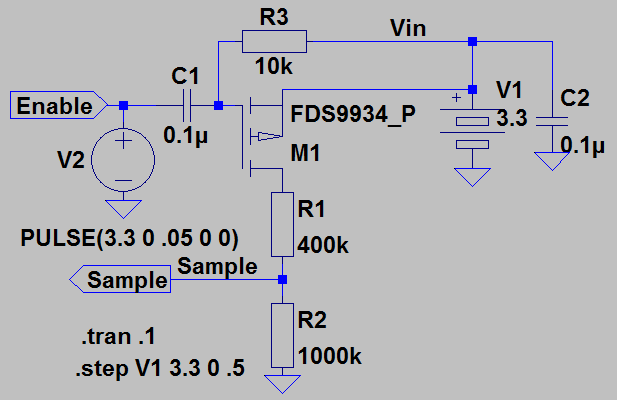
Sorry for the somewhat messy schematic. For those of you unfimiliar with LTspice, this is what the above is:
V1 is the battery to be measured. It's nominal voltage in this case is set to 3.3V. The voltage is stepped from 3.3V to 0 in 0.5 increments in the simulation.
For some noise suppression, it is decoupled with C2 but this makes little difference for the simulation I have made.
The battery voltage is fed through a PMOS FET (M1) before it enters the voltage divider. Below, I will use the term open for the FET when it is not conducting current and closed when it is.
The FET is by default tied in the open state using R3 as pull up to Vin. M1 is closed by grounding it's gate, or in this example by pulling Enable low from the MCU. V2 in this example serves as a crude simulation of the MCU grounding the Enable signal after 0.05s in the simulation time domain (simulation is executed for 0.1s).
The neat feature here is C1, which isolates the MCU output pin from the FET, thus preventing leakage through the MCU. When Enable goes low, M1 is closed momentarily, before C1 regains the charge from the pull from R3 and is opened once again. The value of C1 and R3 can be picked to suit the speed of the MCU (the MCU needs to take the sample before M1 opens).
When Enable is left floating, any charge pushed into C1 is fed back to Vin, and is thus "free".
This also allows the voltage divider to span the entire ADC range (depending on what ADC is used, internal references and such).Below is the resulting waveforms when using a Fairchild FDS9934 as FET (somewhat equivalent breadboard-friendly component could be this).
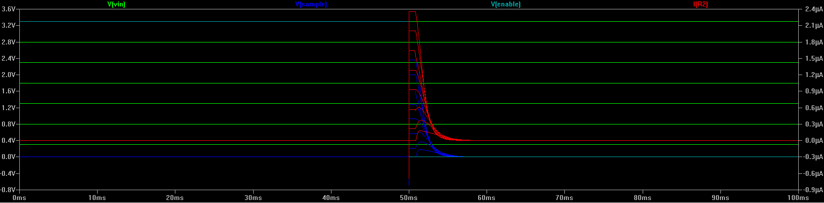
Note here the large span of V(sample) as well as the peak current at the largest voltage level (2.4uA). The current remains constant for a brief period of time (decided by C1 and R3) and then dissipates down to 0, even if Enable is kept low. The current can be reduced by manipulating R1 and R2, but the circuit becomes more sensitive to noise as the current used decreases (as can be seen for lower currents in the simulation, where capacitances in the FET start to make a difference.
-
I have run some simulations on a low-power solution using this setup:
Sorry for the somewhat messy schematic. For those of you unfimiliar with LTspice, this is what the above is:
V1 is the battery to be measured. It's nominal voltage in this case is set to 3.3V. The voltage is stepped from 3.3V to 0 in 0.5 increments in the simulation.
For some noise suppression, it is decoupled with C2 but this makes little difference for the simulation I have made.
The battery voltage is fed through a PMOS FET (M1) before it enters the voltage divider. Below, I will use the term open for the FET when it is not conducting current and closed when it is.
The FET is by default tied in the open state using R3 as pull up to Vin. M1 is closed by grounding it's gate, or in this example by pulling Enable low from the MCU. V2 in this example serves as a crude simulation of the MCU grounding the Enable signal after 0.05s in the simulation time domain (simulation is executed for 0.1s).
The neat feature here is C1, which isolates the MCU output pin from the FET, thus preventing leakage through the MCU. When Enable goes low, M1 is closed momentarily, before C1 regains the charge from the pull from R3 and is opened once again. The value of C1 and R3 can be picked to suit the speed of the MCU (the MCU needs to take the sample before M1 opens).
When Enable is left floating, any charge pushed into C1 is fed back to Vin, and is thus "free".
This also allows the voltage divider to span the entire ADC range (depending on what ADC is used, internal references and such).Below is the resulting waveforms when using a Fairchild FDS9934 as FET (somewhat equivalent breadboard-friendly component could be this).
Note here the large span of V(sample) as well as the peak current at the largest voltage level (2.4uA). The current remains constant for a brief period of time (decided by C1 and R3) and then dissipates down to 0, even if Enable is kept low. The current can be reduced by manipulating R1 and R2, but the circuit becomes more sensitive to noise as the current used decreases (as can be seen for lower currents in the simulation, where capacitances in the FET start to make a difference.
@Anticimex nice, thank you!
-
Thanks guys,
I'll happily elaborate more on the details, but perhaps it is best if you state some specific questions regarding parts of it that are difficult to comprehend. Imo, working with sensors should not require a degree in engineering, so nobody should "feel stupid" for asking questions :) -
Thanks guys,
I'll happily elaborate more on the details, but perhaps it is best if you state some specific questions regarding parts of it that are difficult to comprehend. Imo, working with sensors should not require a degree in engineering, so nobody should "feel stupid" for asking questions :)@Anticimex said:
Imo, working with sensors should not require a degree in engineering, so nobody should "feel stupid" for asking questions :)
When I have questions I will ask :)
But, like @hek, I need to let things 'sink in'.
And I really want to understand.
To be honest I have learned a lot (and spent a lot) since I stumbled upon MySensors.
Wonderful new hobby! -
As long as you connect VCC direct to the battery I do not understand why people opt for using an external voltage divider optionally with a FET to reduce standby current. Additional components and current consumption while only a possible small improvement in accuracy.
For the voltage divider the ADC reading is
1023 x R2 / (R1 + R2) x VccFor the 1.1 Volt reference the reading is
1023 x 1.1/VccIf you are using +/- 10% resistors (or the FET resistance is not measured correct or varies), the accuracy is more or less matching the (uncalibrated) bandgap reference method.
-
As long as you connect VCC direct to the battery I do not understand why people opt for using an external voltage divider optionally with a FET to reduce standby current. Additional components and current consumption while only a possible small improvement in accuracy.
For the voltage divider the ADC reading is
1023 x R2 / (R1 + R2) x VccFor the 1.1 Volt reference the reading is
1023 x 1.1/VccIf you are using +/- 10% resistors (or the FET resistance is not measured correct or varies), the accuracy is more or less matching the (uncalibrated) bandgap reference method.
@daulagari I guess the discussion depends on whether you have a software-mindset or a hardware-mindset.
The software guys currently seem to form a minority on this board...
I still think, after all discussions and distractions, that this way of measuring can be very usefull, when you understand the limitations. -
I have not studied what support for measuring Vcc is built into the Arduino, but if there are support for doing that, I am sure it should be adequate. Regarding the external circuitry, my point is just that if you are going for an external solution, you might just as well design it to consume a minimum amount of current, as that is a one-shot optimization. Yes, it is a couple of extra components, but to me, that outweigh the limitations of the simple voltage divider in the long run.
Personally, I would even consider a battery management unit. Such a thing should be able to handle both charging (if you want that feature) as well as readback (with battery health compensation). -
I guess the discussion depends on whether you have a software-mindset or a hardware-mindset.
Being on this forum you are likely not having a hardware- or software-mindset only ;-)
I have not studied what support for measuring Vcc is built into the Arduino
I think a study is not needed, the ADC ref power is VCC and there is a 1.1 V bandgap in the Arduino that you can measure; that's the whole trick.
Yes, somewhat more funky like a battery management unit can for sure make sense.
-
I guess the discussion depends on whether you have a software-mindset or a hardware-mindset.
Being on this forum you are likely not having a hardware- or software-mindset only ;-)
I have not studied what support for measuring Vcc is built into the Arduino
I think a study is not needed, the ADC ref power is VCC and there is a 1.1 V bandgap in the Arduino that you can measure; that's the whole trick.
Yes, somewhat more funky like a battery management unit can for sure make sense.
@daulagari I see. Then as the whole topic suggests, it should suffice to use internal functionality to determine battery level if batt level = vcc. But some form of external circuitry is required if vcc is regulated. And I don't see a big reason to put a lot of effort into making a high precision solution for monitoring battery of "our" small nodes. But the current proposal of a simple voltage divider is a bit too wasteful imo (off topic).
-
As long as you connect VCC direct to the battery I do not understand why people opt for using an external voltage divider optionally with a FET to reduce standby current. Additional components and current consumption while only a possible small improvement in accuracy.
For the voltage divider the ADC reading is
1023 x R2 / (R1 + R2) x VccFor the 1.1 Volt reference the reading is
1023 x 1.1/VccIf you are using +/- 10% resistors (or the FET resistance is not measured correct or varies), the accuracy is more or less matching the (uncalibrated) bandgap reference method.
@daulagari said:
As long as you current VCC direct to the battery I do not understand why people opt for using an external voltage divider
For the voltage divider the ADC reading is
1023 x R2 / (R1 + R2) x VccFor the 1.1 Volt reference the reading is
1023 x 1.1/VccAn external voltage divider is useful only if you are NOT connecting the measured battery directly to VCC (ie: useful only if you are using a regulator of some sort between VBatt and VCC - whether linear, buck or boost).
Your first calculation doesn't take the reference in to account. The reading is really:
1023/Vref x R2 / (R1+R2) * VBatt. If VBatt is also VCC and VRef is also VCC, then the ADC reading is based only on the constant resistor ratio, independent of battery power (VBatt and VRef cancel out if both are VCC).So when using the default VCC as Vref, the Vbatt voltage divider is only useful when VCC is NOT VBatt.. in that case, if VBatt is the same as VCC, using an external divider is not an alternate technique with wasted components, it's just a non-starter period.
-
@Zeph: Fully agreed.
Your first calculation doesn't take the reference in to account. The reading is really:
1023/Vref x R2 / (R1+R2) * VBatt.My formula's were for the case VCC = Vbatt but yes your formula is more generic but reduces to the same when VCC = Vbatt.
-
Hi there!
Inspired by the Blog entry at http://provideyourown.com/2012/secret-arduino-voltmeter-measure-battery-voltage/ I decided to write a simple Arduino library to measure VCC level without any external components!
This library can be used to measure the VCC level from e.g. battery powered sensors that do not use a voltage regulator but are powered directly from the batteries and send the battery level to the gateway.The trick is to use the AVR's internal 1.1V reference to measure AVcc. This does not require an external voltage divider.
The Vcc component can report the VCC level either in volts, or in percentage. Reporting in percentage is a nice way to report the battery level in MySensors!
For example:#include <Vcc.h> const float VccExpected = 3.0; const float VccCorrection = 2.860/2.92; // Measured Vcc by multimeter divided by reported Vcc Vcc vcc(VccCorrection); static int oldBatteryPcnt = 0; void loop() { int batteryPcnt = (int)vcc.Read_Perc(VccExpected); if (oldBatteryPcnt != batteryPcnt) { gw.sendBatteryLevel(batteryPcnt); oldBatteryPcnt = batteryPcnt; } }Deviations can easily be corrected for by running one of the example sketches and at the same time measure VCC with a multimeter.
The correction factor should be entered as (VCC multimeter/VCC reported) in the constructor of the Vcc component (the VccCorrection parameter in the example above).
See the example sketches and code for more info.The library can be found at: https://github.com/Yveaux/arduino_vcc
Or download as ZIP: https://github.com/Yveaux/arduino_vcc/archive/master.zipHave fun!
@Yveaux The only comment i have to this lib now then I'm using it is that you should not use floats but int instead, and just have an imaginary decimal point and divide at later stage to save program memory..
And talking about this, I should probably start a new thread talking about optimizations, There are some to be done in the mysensors-lib also.. -
@Yveaux The only comment i have to this lib now then I'm using it is that you should not use floats but int instead, and just have an imaginary decimal point and divide at later stage to save program memory..
And talking about this, I should probably start a new thread talking about optimizations, There are some to be done in the mysensors-lib also..@Damme I'm fully aware of the use of floating point and the penalties that come with it, don't worry.
But I just poored existing code into a library. I didn't put any effort in optimizing it.
Btw Arduino sketches tend to be very inefficient on resource usage, starting by using a 16 bit int type... -
Thread Rival ... ;-)
So in trying to understand and improve battery life (currently using V div on Step Reg. Vin (VBatt) in my sensors, why can't I just measure the VCC on AO without the V div as VBAT will never exceed VCC,?
Trying to figure out what fundamental I'm missing here....
-
Thread Rival ... ;-)
So in trying to understand and improve battery life (currently using V div on Step Reg. Vin (VBatt) in my sensors, why can't I just measure the VCC on AO without the V div as VBAT will never exceed VCC,?
Trying to figure out what fundamental I'm missing here....
@ServiceXp So you want to connect VCC of the ATMega to ana analog input pin to read the supply level?
If this is your idea, then the ATMega will measure the voltage on an analog input relative to the supply voltage. If the supply voltage of the ATMega starts to drop, the relative voltage measured on the analog input will not change w.r.t. VCC.
By using a voltage divider you bring the voltage to be measured within 0,..,1.1V range (roughly). The ATMega has an internal 1.1V voltage reference which will remain stable when VCC drops, and thus can be used to meaure the supply level using a voltage divider.
Hello! It looks like you're interested in this conversation, but you don't have an account yet.
Getting fed up of having to scroll through the same posts each visit? When you register for an account, you'll always come back to exactly where you were before, and choose to be notified of new replies (either via email, or push notification). You'll also be able to save bookmarks and upvote posts to show your appreciation to other community members.
With your input, this post could be even better 💗
Register Login