RGB LED strip

-
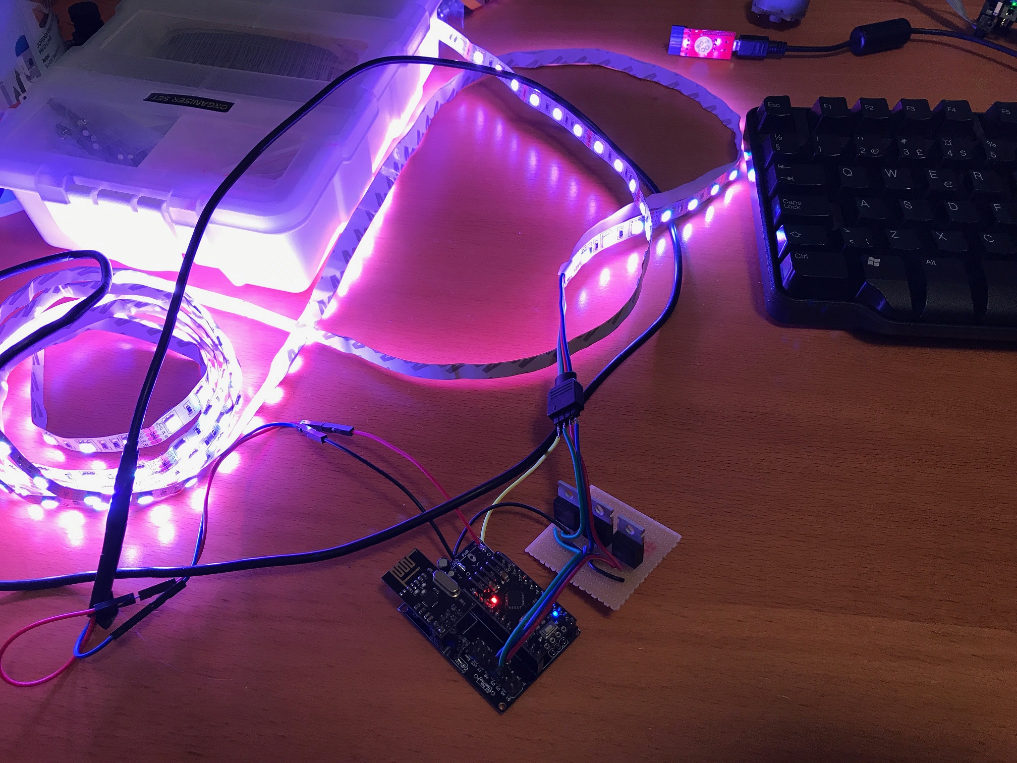
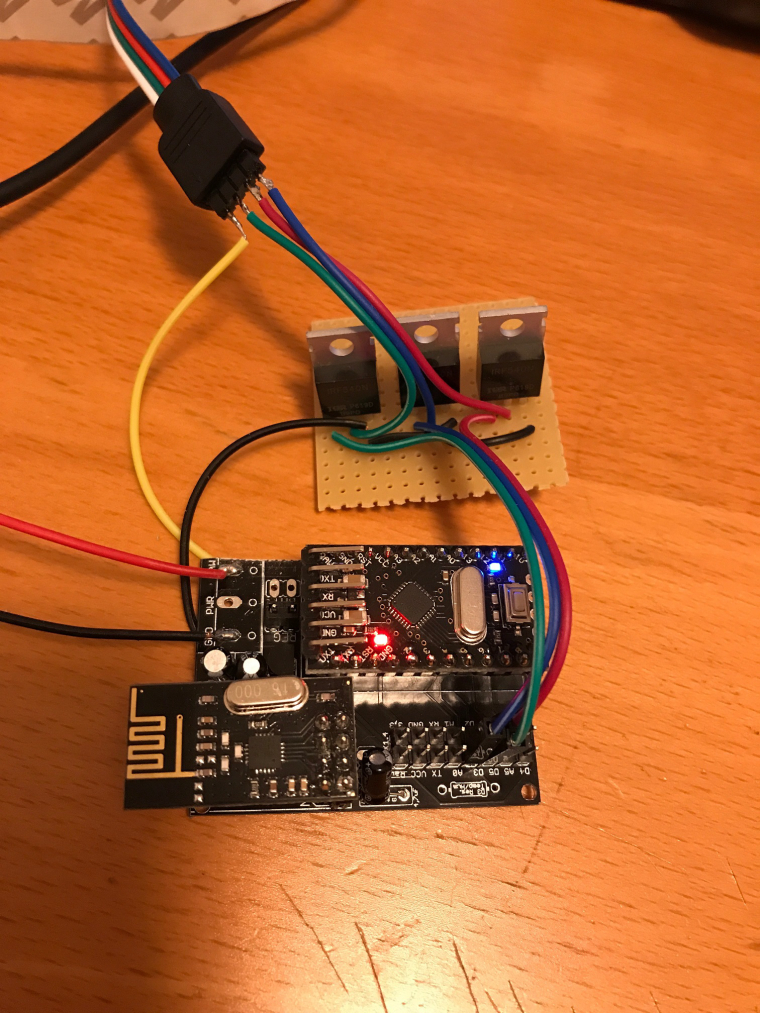
I built a RGB LED strip controllable via mysensor, based on a 12V RGB LED strip and three IRF540 MOSFETs. The arduino is a 5V pro mini clone that I feed with 12V on the RAW pin.
I followed the guide on https://learn.adafruit.com/rgb-led-strips/usage for wiring the MOSFETS and the LED strip. I used the Newbie PCB by @sundberg84 for holding the arduino and the radio, but put the MOSFETs on a separate prototyping board (maybe next time I'll try to solder them to the prototyping area of the Newbie PCB).
I implemented a fading feature in the sketch, so it can fade slowly between colors or on/off. The speed is controlled by sending a V_VAR1 message with the speed (typical value could be around 200-300 for a nice effect). Speed = 0 means fading is off.
Here is the code:
/**
 * This program is free software; you can redistribute it and/or
 * modify it under the terms of the GNU General Public License
 * version 2 as published by the Free Software Foundation.
 *
 * LED STRIP sketch for Mysensors
 *******************************
 *
 * REVISION HISTORY
 * 1.0
 *   Based on the example sketch in mysensors
 * 1.1
 *   fadespeed parameter (send as V_VAR1 message)
 *   HomeAssistant compatible (send status to ack)
 */

#define MY_OTA_FIRMWARE_FEATURE
#define MY_NODE_ID AUTO

#define MY_RADIO_NRF24

#include <MySensors.h>

#define CHILD_ID_LIGHT 1

#define SN "LED Strip"
#define SV "1.1"

MyMessage lightMsg(CHILD_ID_LIGHT, V_LIGHT);
MyMessage rgbMsg(CHILD_ID_LIGHT, V_RGB);
MyMessage dimmerMsg(CHILD_ID_LIGHT, V_DIMMER);

byte red = 255;
byte green = 255;
byte blue = 255;
byte r0 = 255;
byte g0 = 255;
byte b0 = 255;
char rgbstring[] = "ffffff";

int on_off_status = 0;
int dimmerlevel = 100;
int fadespeed = 0;

#define REDPIN 6
#define GREENPIN 5
#define BLUEPIN 3

void setup()
{
  // Fix the PWM timer. Without this the LEDs will flicker.
  TCCR0A = _BV(COM0A1) | _BV(COM0B1) | _BV(WGM00);

  // Output pins
  pinMode(REDPIN, OUTPUT);
  pinMode(GREENPIN, OUTPUT);
  pinMode(BLUEPIN, OUTPUT);

}

void presentation()
{
	// Send the Sketch Version Information to the Gateway
	sendSketchInfo(SN, SV);
	present(CHILD_ID_LIGHT, S_RGB_LIGHT);
}

void loop()
{
  static bool first_message_sent = false;
  if ( first_message_sent == false ) {
    Serial.println( "Sending initial state..." );
    set_hw_status();
    send_status();
    first_message_sent = true;
  }
}

void receive(const MyMessage &message)
{
  int val;

	if (message.type == V_RGB) {
		Serial.println( "V_RGB command: " );
    Serial.println(message.data);
    long number = (long) strtol( message.data, NULL, 16);

    // Save old value
    strcpy(rgbstring, message.data);

    // Split it up into r, g, b values
    red = number >> 16;
    green = number >> 8 & 0xFF;
    blue = number & 0xFF;

    send_status();
    set_hw_status();

	} else if (message.type == V_LIGHT || message.type == V_STATUS) {
    Serial.println( "V_LIGHT command: " );
    Serial.println(message.data);
    val = atoi(message.data);
    if (val == 0 or val == 1) {
      on_off_status = val;
      send_status();
      set_hw_status();
    }

  } else if (message.type == V_DIMMER || message.type == V_PERCENTAGE) {
    Serial.print( "V_DIMMER command: " );
    Serial.println(message.data);
    val = atoi(message.data);
    if (val >= 0 and val <=100) {
      dimmerlevel = val;
      send_status();
      set_hw_status();
    }

  } else if (message.type == V_VAR1 ) {
    Serial.print( "V_VAR1 command: " );
    Serial.println(message.data);
    val = atoi(message.data);
    if (val >= 0 and val <= 2000) {
      fadespeed = val;
    }

	} else {
		Serial.println( "Invalid command received..." );
		return;
	}

}

void set_rgb(int r, int g, int b) {
  analogWrite(REDPIN, r);
  analogWrite(GREENPIN, g);
  analogWrite(BLUEPIN, b);
}

void set_hw_status() {
  int r = on_off_status * (int)(red * dimmerlevel/100.0);
  int g = on_off_status * (int)(green * dimmerlevel/100.0);
  int b = on_off_status * (int)(blue * dimmerlevel/100.0);

  if (fadespeed >0) {

    float dr = (r - r0) / float(fadespeed);
    float db = (b - b0) / float(fadespeed);
    float dg = (g - g0) / float(fadespeed);

    for (int x = 0;  x < fadespeed; x++) {
      set_rgb(r0 + dr*x, g0 + dg*x, b0 + db*x);
      delay(100);
    }
  }

  set_rgb(r, g, b);

  r0 = r;
  b0 = b;
  g0 = g;

}


void send_status() {
  send(rgbMsg.set(rgbstring));
  send(lightMsg.set(on_off_status));
  send(dimmerMsg.set(dimmerlevel));
}
I have a MQTT gateway and I can turn the strip on, set the color to pink and fade speed to 500 by the following commands:
mosquitto_pub -t mysensors-in/240/1/1/0/40 -m ff6060
mosquitto_pub -t mysensors-in/240/1/1/0/24 -m 500
mosquitto_pub -t mysensors-in/240/1/1/0/2 -m 1
A couple of pics:

@maghac said in RGB LED strip:
Nice work!! I have some led strips laying around... maybe I have to start using them.The arduino is a 5V pro mini clone that I feed with 12V on the RAW pin.
Just a hint, this makes me nervous because Ive seen many clones with 12specs but the voltage reg is so cheap/bad it will not make it for long. Be careful using 12v on raw on the clones.
-
Nice project! The code looks really clean, I might just copy some of that for the next version of firmware for my rgb(w) node. Have you looked into how to fix the non linear fading when using pwm?
I had started to but never finished that.@LastSamurai Thanks!
I started looking into it but realized it's a bit complex since you probably need to consider the characteristics of the MOSFETs as well. Also, when playing with it I've realized that fading between colours actually looks linear (e.g moving from ff8080 to 00ff80 is actually quite smooth), which means you need to consider the overall intensity too.
Another interesting situation is when the user sets colour 808080 and intensity 100% compared to colour ffffff and intensity 50%. In my sketch this ends up as the same value.
-
@maghac said in RGB LED strip:
Nice work!! I have some led strips laying around... maybe I have to start using them.The arduino is a 5V pro mini clone that I feed with 12V on the RAW pin.
Just a hint, this makes me nervous because Ive seen many clones with 12specs but the voltage reg is so cheap/bad it will not make it for long. Be careful using 12v on raw on the clones.
@sundberg84 Thanks.
Yes, I've noticed that some of them are a bit unreliable when fed with 12V. Maybe I will put a separate regulator to drive the board with 5V instead.
-
I noticed that the indents in the sketch are a bit off, I guess there's a mix of spaces and tabs in the file :) I blame the crappy editor in the Arduino IDE.
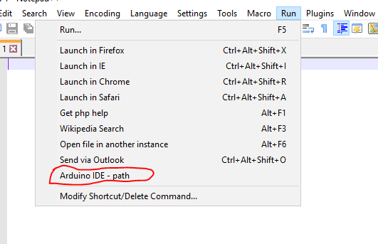
As a side note, has anyone managed to set up a Arduino development environment based on Notepad++ or some other editor? I know about platformio.org but I never managed to make friends with Atom so I haven't looked into it.
-
I noticed that the indents in the sketch are a bit off, I guess there's a mix of spaces and tabs in the file :) I blame the crappy editor in the Arduino IDE.
As a side note, has anyone managed to set up a Arduino development environment based on Notepad++ or some other editor? I know about platformio.org but I never managed to make friends with Atom so I haven't looked into it.
-
@LastSamurai Thanks!
I started looking into it but realized it's a bit complex since you probably need to consider the characteristics of the MOSFETs as well. Also, when playing with it I've realized that fading between colours actually looks linear (e.g moving from ff8080 to 00ff80 is actually quite smooth), which means you need to consider the overall intensity too.
Another interesting situation is when the user sets colour 808080 and intensity 100% compared to colour ffffff and intensity 50%. In my sketch this ends up as the same value.
@maghac The FastLed library has some functions for linear fading. The characteristics of the Mosfet's can be ignored. When using PWM these are used as switches (i.e. on/off).
For inspiration: this sketch was for a RGBW strip and uses the FastLEDnscale8()for smooth fading. Also there is a non-blocking version of the fading routine and a state machine to have button control.
(the 'W' in the RGBW can easily be removed. It is calculated here as a kind of greatest common divisor of RGB)/* PROJECT: MySensors / RGB light NEOPIXEL PROGRAMMER: AWI DATE: october 10, 2015/ last update: september 20, 2016 FILE: AWI_Wall_LIght_x.ino LICENSE: Public domain Hardware: RGBW Pro Mini and MySensors 2.0, Special: uses Fastled library (great & fast RBG/HSV universal library) https://github.com/FastLED/FastLED SUMMARY: Different patterns and brightness settings Button switches on/off and color with long press Remarks: Fixed node-id Change log: 20160915 - Updated to MySensors 2.0 20160920 - Changed state change to dimmer i.s.o. switch() 20161120 - Various small adjustments 20170120 - Change to RGBW non addressable strip */ //**** MySensors ***** // Enable debug prints to serial monitor #define MY_DEBUG #define MY_RADIO_NRF24 // Enable and select radio type attached #define MY_NODE_ID 63 // 62 #define NODE_TXT "W 63" // Text to add to sensor name // change the pins to free up the pwm pin for led control #define MY_RF24_CE_PIN 4 //<-- NOTE!!! changed, the default is 9 #define MY_RF24_CS_PIN 10 // default is 10 //#define RF24_PA_LEVEL RF24_PA_MAX // helpers #define LOCAL_DEBUG // enable if print wanted #ifdef LOCAL_DEBUG #define Sprint(...) (Serial.print( __VA_ARGS__)) // macro as substitute for print, enable if no print wanted #define Sprintln(...) (Serial.println( __VA_ARGS__)) // macro as substitute for println #else #define Sprint(a) #define Sprintln(a) #endif #include <SPI.h> // My Sensors #include <MySensors.h> #include <FastLED.h> // https://github.com/FastLED/FastLED #include "Button.h" // https://github.com/JChristensen/Button // Arduino pin attached to drivers const int RED_PIN = 5 ; const int WHITE_PIN = 9 ; const int GREEN_PIN = 3 ; const int BLUE_PIN = 6 ; const int buttonPin = 7 ; // push button const int RGB_LightChild = 0 ; // Child Id's, standard light child on/off/ dim const int RGB_RGBChild = 1 ; // RGB light child (on/off/dim/color, if controller supports V_RBG)) CRGB strip ; // RGB(W) strip (Fastled) uint8_t stripW = 0 ; // White component uint8_t actualBrightness = 0xFF ; // actual strip brightness // Kelving colors: Light & daylight (in Fastled reference only) /// 1900 Kelvin Candle=0xFF9329 /* 1900 K, 255, 147, 41 */, /// 2600 Kelvin Tungsten40W=0xFFC58F /* 2600 K, 255, 197, 143 */, /// 2850 Kelvin Tungsten100W=0xFFD6AA /* 2850 K, 255, 214, 170 */, /// 3200 Kelvin Halogen=0xFFF1E0 /* 3200 K, 255, 241, 224 */, /// 5200 Kelvin CarbonArc=0xFFFAF4 /* 5200 K, 255, 250, 244 */, /// 5400 Kelvin HighNoonSun=0xFFFFFB /* 5400 K, 255, 255, 251 */, /// 6000 Kelvin DirectSunlight=0xFFFFFF /* 6000 K, 255, 255, 255 */, /// 7000 Kelvin OvercastSky=0xC9E2FF /* 7000 K, 201, 226, 255 */, /// 20000 Kelvin ClearBlueSky=0x409CFF /* 20000 K, 64, 156, 255 */ char setRGBvalue[] = "FEBC5400"; CRGB curRGB = 0xFEBC54 ; // Controller sent RGB(W) value, default tungsten40W "FFC58F" uint16_t curBrightness = 0xFF, setBrightness = 0xFF ; // Brightness globals (actualBrightness) unsigned long updateBrightnessDelay, lastBrightnessUpdate ; // Brightness timers int RGBonoff ; // OnOff flag unsigned long idleTimer = millis() ; // return to idle timer const unsigned long idleTime = 10000UL; // return to idle after 10 secs const unsigned long dimTime = 1000UL; // dim period const unsigned long heartbeatInterval = 1 * 60UL * 1000UL ; // heartbeatinterval, just to let the controller know I am alive unsigned long heartbeatCounter = 0 ; MyMessage lightRGBMsg(RGB_LightChild, V_RGB); // standard messages, light MyMessage lightdimmerMsG(RGB_LightChild ,V_DIMMER); MyMessage lightOnOffMessage(RGB_LightChild, V_STATUS); Button myBtn(buttonPin, true, true, 20); //Declare the button (pin, pull_up, invert, debounce_ms) // Simple state machine for button state enum {sIdle, sBrightness, sPattern} ; // simple state machine for button press int State ; void setup() { pinMode(RED_PIN, OUTPUT); pinMode(GREEN_PIN, OUTPUT); pinMode(BLUE_PIN, OUTPUT); pinMode(WHITE_PIN, OUTPUT); request(RGB_LightChild, V_RGBW) ; /*for(int i = 0 ; i < 6 ; i++) { // get color value from EEPROM (8 char for RGBW) setRGBvalue[i] = loadState(i) ; } curRGB = strtol( setRGBvalue, NULL, 16); // copy the RGB value to the led Strip (convert to long) showAnalogRGB() ; */ } void presentation(){ // MySensors sendSketchInfo("AWI RGBW strip " NODE_TXT, "2.0"); wait(50) ; present(RGB_RGBChild, S_RGB_LIGHT, "RGB RGBW strip " NODE_TXT); wait(50) ; } // read button and act accordingly // short press: on/off // longer press: set patterns with following short press // long press: set brightness increase void loop() { myBtn.read(); //Read the button (only read) unsigned long now = millis(); // loop timer reference switch (State) { case sIdle: // default state, browse through patterns if (myBtn.wasReleased()){ // light on/ off in idle RGBonoff = !RGBonoff ; // invert light state setLightBrightness((RGBonoff == 1)?setBrightness:0, dimTime); send(lightOnOffMessage.set(RGBonoff)); // and update controller } else if (myBtn.pressedFor(800)){ // move to Pattern update state with long press idleTimer = now ; // return to idle after ... State = sPattern ; } break ; case sPattern: // entered after long press/ change colors (tbd) if (myBtn.pressedFor(4000)){ // when press even longer move to Brightness update State = sBrightness ; } else if (myBtn.wasPressed()){ //setPattern = (setPattern + 1) % lastPatternIdx ; // increase pattern and wrap //setLightPattern((setPattern), 500 ); idleTimer = now ; } else if ( now > idleTime + idleTimer ){ // return to idle after ... State = sIdle ; } break ; case sBrightness: // entered after looong press if (myBtn.wasPressed()){ // if pressed again increase brightness setLightBrightness((curBrightness+0x1F) % 0xFF, 0) ; // increase brightness and wrap (0..0xFF) idleTimer = now ; } else if ( now > idleTime + idleTimer ){ // return to idle after ... State = sIdle ; } break ; default : State = sIdle ; break ; } updateLightBrightness(); // update Brightness if time if ( now > heartbeatCounter + heartbeatInterval){ // heartbeat every hour sendHeartbeat(); heartbeatCounter = now ; } } // Sets the light brightness, takes value and time (ms) as input void setLightBrightness(int newBrightness, unsigned long updateTime){ // global: curBrightness, actualBrightness, updateBrightnessDelay updateBrightnessDelay = updateTime / 0xFF ; // delay = time / max steps curBrightness = newBrightness ; // set curBrightness to new value, rest is done in update } // Update the light brightness if time void updateLightBrightness(){ // global: curBrightness, actualBrightness, updateBrightnessDelay, lastBrightnessUpdate ; //static byte actualBrightness ; // store real brightness state for slow dim unsigned long now = millis() ; if (now > lastBrightnessUpdate + updateBrightnessDelay){// check if time for update if ( actualBrightness > curBrightness) { --actualBrightness ; showAnalogRGB() ; } else if ( actualBrightness < curBrightness){ ++actualBrightness ; showAnalogRGB() ; } lastBrightnessUpdate = now ; } } // Incoming messages from MySensors void receive(const MyMessage &message){ int ID = message.sensor; Serial.print("Sensor: "); Serial.println(ID); switch (ID){ case RGB_LightChild: // same behaviour as RGB child/ fall through case RGB_RGBChild: // if controller can handle V_RGB if (message.type == V_RGB) { // check for RGB type strcpy(setRGBvalue, message.getString()); // get the payload curRGB = strtoul( setRGBvalue, NULL, 16) ; // copy the RGB value to the led Strip (convert to long) } else if (message.type == V_RGBW) { // check for RGB type strcpy(setRGBvalue, message.getString()); // get the payload curRGB = strtoul( setRGBvalue, NULL, 16) >> 8; // copy the RGB value to the led Strip (convert to long) } else if (message.type == V_DIMMER) { // if DIMMER type, adjust brightness setBrightness = map(message.getInt(), 0, 100, 0, 255); setLightBrightness(setBrightness, dimTime) ; } else if (message.type == V_STATUS) { // if on/off type, toggle brightness RGBonoff = message.getInt(); setLightBrightness((RGBonoff == 1)?setBrightness:0, dimTime); } break ; } showAnalogRGB(); dispRGBstat(); } // showAnalogRGB: this is like FastLED.show(), but outputs on // analog PWM output pins instead of sending data to an intelligent, // pixel-addressable LED strip. void showAnalogRGB(){ strip = curRGB ; strip.nscale8(actualBrightness) ; int commonRGB = min(min(strip.r, strip.g), strip.b) ; // smallest value is White component strip.r -= commonRGB ; strip.g -= commonRGB ; strip.b -= commonRGB ; stripW = commonRGB ; Sprint("Color RGBW ") ; Sprint(strip.r, HEX); Sprint(" ") ; Sprint(strip.g, HEX); Sprint(" ") ; Sprint(strip.b, HEX); Sprint(" ") ; Sprintln(stripW, HEX) ; analogWrite(RED_PIN, strip.r ); analogWrite(GREEN_PIN, strip.g ); analogWrite(BLUE_PIN, strip.b ); analogWrite(WHITE_PIN, stripW ) ; } // debug // display the status of all RGB: controller, requested, real void dispRGBstat(void){ Serial.print(" Color: "); Serial.print(setRGBvalue); Serial.print(" Brightness: "); Serial.println(setBrightness); } ``` -
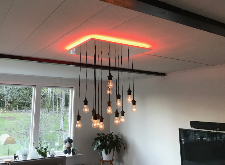
I'd thought I'd share a pic now that the led strip has been mounted. Unfortunately the iphone camera doesn't have enough dynamic range to capture the light correctly - it looks a lot better in reality!
Through some HomeAssistant/tellstick magic I can also turn it on and off using a normal 433Mhz remote instead of having to send MQTT messages from the command line. This increased the WAF considerably :)
-
I built a RGB LED strip controllable via mysensor, based on a 12V RGB LED strip and three IRF540 MOSFETs. The arduino is a 5V pro mini clone that I feed with 12V on the RAW pin.
I followed the guide on https://learn.adafruit.com/rgb-led-strips/usage for wiring the MOSFETS and the LED strip. I used the Newbie PCB by @sundberg84 for holding the arduino and the radio, but put the MOSFETs on a separate prototyping board (maybe next time I'll try to solder them to the prototyping area of the Newbie PCB).
I implemented a fading feature in the sketch, so it can fade slowly between colors or on/off. The speed is controlled by sending a V_VAR1 message with the speed (typical value could be around 200-300 for a nice effect). Speed = 0 means fading is off.
Here is the code:
/**
 * This program is free software; you can redistribute it and/or
 * modify it under the terms of the GNU General Public License
 * version 2 as published by the Free Software Foundation.
 *
 * LED STRIP sketch for Mysensors
 *******************************
 *
 * REVISION HISTORY
 * 1.0
 *   Based on the example sketch in mysensors
 * 1.1
 *   fadespeed parameter (send as V_VAR1 message)
 *   HomeAssistant compatible (send status to ack)
 */

#define MY_OTA_FIRMWARE_FEATURE
#define MY_NODE_ID AUTO

#define MY_RADIO_NRF24

#include <MySensors.h>

#define CHILD_ID_LIGHT 1

#define SN "LED Strip"
#define SV "1.1"

MyMessage lightMsg(CHILD_ID_LIGHT, V_LIGHT);
MyMessage rgbMsg(CHILD_ID_LIGHT, V_RGB);
MyMessage dimmerMsg(CHILD_ID_LIGHT, V_DIMMER);

byte red = 255;
byte green = 255;
byte blue = 255;
byte r0 = 255;
byte g0 = 255;
byte b0 = 255;
char rgbstring[] = "ffffff";

int on_off_status = 0;
int dimmerlevel = 100;
int fadespeed = 0;

#define REDPIN 6
#define GREENPIN 5
#define BLUEPIN 3

void setup()
{
  // Fix the PWM timer. Without this the LEDs will flicker.
  TCCR0A = _BV(COM0A1) | _BV(COM0B1) | _BV(WGM00);

  // Output pins
  pinMode(REDPIN, OUTPUT);
  pinMode(GREENPIN, OUTPUT);
  pinMode(BLUEPIN, OUTPUT);

}

void presentation()
{
	// Send the Sketch Version Information to the Gateway
	sendSketchInfo(SN, SV);
	present(CHILD_ID_LIGHT, S_RGB_LIGHT);
}

void loop()
{
  static bool first_message_sent = false;
  if ( first_message_sent == false ) {
    Serial.println( "Sending initial state..." );
    set_hw_status();
    send_status();
    first_message_sent = true;
  }
}

void receive(const MyMessage &message)
{
  int val;

	if (message.type == V_RGB) {
		Serial.println( "V_RGB command: " );
    Serial.println(message.data);
    long number = (long) strtol( message.data, NULL, 16);

    // Save old value
    strcpy(rgbstring, message.data);

    // Split it up into r, g, b values
    red = number >> 16;
    green = number >> 8 & 0xFF;
    blue = number & 0xFF;

    send_status();
    set_hw_status();

	} else if (message.type == V_LIGHT || message.type == V_STATUS) {
    Serial.println( "V_LIGHT command: " );
    Serial.println(message.data);
    val = atoi(message.data);
    if (val == 0 or val == 1) {
      on_off_status = val;
      send_status();
      set_hw_status();
    }

  } else if (message.type == V_DIMMER || message.type == V_PERCENTAGE) {
    Serial.print( "V_DIMMER command: " );
    Serial.println(message.data);
    val = atoi(message.data);
    if (val >= 0 and val <=100) {
      dimmerlevel = val;
      send_status();
      set_hw_status();
    }

  } else if (message.type == V_VAR1 ) {
    Serial.print( "V_VAR1 command: " );
    Serial.println(message.data);
    val = atoi(message.data);
    if (val >= 0 and val <= 2000) {
      fadespeed = val;
    }

	} else {
		Serial.println( "Invalid command received..." );
		return;
	}

}

void set_rgb(int r, int g, int b) {
  analogWrite(REDPIN, r);
  analogWrite(GREENPIN, g);
  analogWrite(BLUEPIN, b);
}

void set_hw_status() {
  int r = on_off_status * (int)(red * dimmerlevel/100.0);
  int g = on_off_status * (int)(green * dimmerlevel/100.0);
  int b = on_off_status * (int)(blue * dimmerlevel/100.0);

  if (fadespeed >0) {

    float dr = (r - r0) / float(fadespeed);
    float db = (b - b0) / float(fadespeed);
    float dg = (g - g0) / float(fadespeed);

    for (int x = 0;  x < fadespeed; x++) {
      set_rgb(r0 + dr*x, g0 + dg*x, b0 + db*x);
      delay(100);
    }
  }

  set_rgb(r, g, b);

  r0 = r;
  b0 = b;
  g0 = g;

}


void send_status() {
  send(rgbMsg.set(rgbstring));
  send(lightMsg.set(on_off_status));
  send(dimmerMsg.set(dimmerlevel));
}
I have a MQTT gateway and I can turn the strip on, set the color to pink and fade speed to 500 by the following commands:
mosquitto_pub -t mysensors-in/240/1/1/0/40 -m ff6060
mosquitto_pub -t mysensors-in/240/1/1/0/24 -m 500
mosquitto_pub -t mysensors-in/240/1/1/0/2 -m 1
A couple of pics:
@maghac , great work!!!
I want to build a battery powered Mood Light based on your sketch and RGB Common Cathode Leds (4 or 5 of them).
Before getting those RGB leds yet (already ordered but it takes 2 months to receive) I tested your sketch with three ordinary 3 mm colored leds - Green, Red and Yellow (should be blue but I don´t have it) and got it running on Home Assistant. On batteries as well. Color selection and Dimmer working as well...
But I don´t get fading effects (called by transition time on Home Assistant). No matter how long I ask the transition it changes the same time I ask.
Serial monitor never shows that V_VAR1 message type. Was it supposed to show it?
What did I miss?Thanks.
-
@OliverDog, thanks!
The V_VAR1 message is used to set the speed of the fading (e.g the time between stepping the RGB values towards the value received with the V_RGB message). Not sure why it doesn't work for you, but maybe it's related to the fact that you don't have the real RGB leds?
You may be interested to know that I have implemented a new version of this sketch. The problem with the old one is that it did the fading in a loop which meant that no new commands were processed during the fade. The new version implements it differently so that messages can be received while the light is fading in a sort of multitasking fashion. This opened up the possibility to implement "programs" that control the LED strip in the background while the device is still receiving messages (e.g during a slow fade to green I can tell it to turn off or to fade to blue instead, without having to wait for the current fade to stop). I have implemented two such programs - one is a sort of an alarm mode (blink white on/off) and the other is a relax program (very slow fade between various pastel colours). To enable the programs, you send a V_VAR2 message with a number: 0: normal (e.g fixed to one colour), 1: alarm and 2: relax.
Since V_VAR2 is message type 25, this is the corresponding MQTT message to enable the relax program:
mosquitto_pub -t mysensors-in/2/1/1/0/25 -m 2Code is below. I intend to update it further (i.e the "party" program is missing! :) ) and then I'll post the new versions here.
Have fun!
/** * This program is free software; you can redistribute it and/or * modify it under the terms of the GNU General Public License * version 2 as published by the Free Software Foundation. * * LED STRIP sketch for Mysensors ******************************* * * REVISION HISTORY * 1.0 * Based on the example sketch in mysensors * 1.1 * fadespeed parameter (send as V_VAR1 message) * HomeAssistant compatible (send status to ack) * 1.2 * OTA support * 1.3 * Power-on self test * 1.4 * Bug fix * 1.5 * Other default values * 1.6 * Repeater feature * 1.7 * Multitasking. Alarm, Relax and normal modes. */ #define MY_OTA_FIRMWARE_FEATURE #define MY_REPEATER_FEATURE #define MY_NODE_ID AUTO #define MY_RADIO_NRF24 #define MY_DEBUG #include <MySensors.h> #define CHILD_ID_LIGHT 1 #define SN "LED Strip" #define SV "1.7" MyMessage lightMsg(CHILD_ID_LIGHT, V_LIGHT); MyMessage rgbMsg(CHILD_ID_LIGHT, V_RGB); MyMessage dimmerMsg(CHILD_ID_LIGHT, V_DIMMER); int current_r = 255; int current_g = 255; int current_b = 255; int target_r = 255; int target_g = 255; int target_b = 255; int save_r; int save_g; int save_b; float delta_r = 0.0; float delta_g = 0.0; float delta_b = 0.0; char rgbstring[] = "ffffff"; int on_off_status = 0; int dimmerlevel = 100; int fadespeed = 20; unsigned long last_update = 0; int tick_length = 10; int fade_step = 0; int program_timer; int program_cycle; #define REDPIN 6 #define GREENPIN 5 #define BLUEPIN 3 #define LIGHT_NORMAL 0 #define LIGHT_FADING 1 #define PROGRAM_NORMAL 0 #define PROGRAM_ALARM 1 #define PROGRAM_RELAX 2 int light_mode = LIGHT_NORMAL; int program_mode = PROGRAM_NORMAL; #define RELAX_SPEED 50 #define MAX_CYCLES_RELAX 7 const int program_param_RELAX[MAX_CYCLES_RELAX][3] = { {255, 32, 0}, {255, 32, 16}, {255, 16, 32}, {255, 128, 0}, {255, 32, 00}, {255, 32, 32}, {255, 0, 32} }; void setup() { // Fix the PWM timer. Without this the LEDs will flicker. TCCR0A = _BV(COM0A1) | _BV(COM0B1) | _BV(WGM00); // Output pins pinMode(REDPIN, OUTPUT); pinMode(GREENPIN, OUTPUT); pinMode(BLUEPIN, OUTPUT); } void presentation() { // Send the Sketch Version Information to the Gateway sendSketchInfo(SN, SV); present(CHILD_ID_LIGHT, S_RGB_LIGHT); } void selftest() { on_off_status = 1; current_r = 255; current_g = 0; current_b = 0; set_hw_status(); wait(100); current_r = 0; current_g = 255; set_hw_status(); wait(100); current_g = 0; current_b = 255; set_hw_status(); wait(100); current_r = 255; current_g = 255; set_hw_status(); wait(100); on_off_status = 0; } void loop() { static bool first_message_sent = false; if ( first_message_sent == false ) { selftest(); set_hw_status(); send_status(1, 1, 1); first_message_sent = true; } unsigned long now = millis(); if (now - last_update > tick_length) { last_update = now; if (light_mode == LIGHT_FADING) { calc_fade(); } if (program_mode > PROGRAM_NORMAL) { handle_program(); } } set_hw_status(); } void receive(const MyMessage &message) { int val; if (message.type == V_RGB) { Serial.print( "V_RGB: " ); Serial.println(message.data); long number = (long) strtol( message.data, NULL, 16); // Save old value strcpy(rgbstring, message.data); // Split it up into r, g, b values int r = number >> 16; int g = number >> 8 & 0xFF; int b = number & 0xFF; init_fade(fadespeed, r, g, b); send_status(0, 0, 1); } else if (message.type == V_LIGHT || message.type == V_STATUS) { Serial.print( "V_LIGHT: " ); Serial.println(message.data); val = atoi(message.data); if (val == 0 or val == 1) { on_off_status = val; send_status(1, 0, 0); } } else if (message.type == V_DIMMER || message.type == V_PERCENTAGE) { Serial.print( "V_DIMMER: " ); Serial.println(message.data); val = atoi(message.data); if (val >= 0 and val <=100) { dimmerlevel = val; send_status(0, 1, 0); } } else if (message.type == V_VAR1 ) { Serial.print( "V_VAR1: " ); Serial.println(message.data); val = atoi(message.data); if (val >= 0 and val <= 2000) { fadespeed = val; } } else if (message.type == V_VAR2 ) { Serial.print( "V_VAR2: " ); Serial.println(message.data); val = atoi(message.data); if (val == PROGRAM_NORMAL) { stop_program(); } else if (val == PROGRAM_ALARM || val == PROGRAM_RELAX) { init_program(val); } } else { Serial.println( "Invalid command received..." ); return; } } void set_rgb(int r, int g, int b) { analogWrite(REDPIN, r); analogWrite(GREENPIN, g); analogWrite(BLUEPIN, b); } void init_program(int program) { program_mode = program; program_cycle = 0; save_rgb(); if (program == PROGRAM_ALARM) { light_mode = LIGHT_NORMAL; current_r = 255; current_g = 255; current_b = 255; program_timer = 50; } else if (program == PROGRAM_RELAX) { program_timer = 300; init_fade(fadespeed, program_param_RELAX[program_cycle][0], program_param_RELAX[program_cycle][1], program_param_RELAX[program_cycle][2]); } } void handle_program() { program_timer--; if (program_mode == PROGRAM_ALARM) { if (program_timer == 0) { program_timer = 50; if (program_cycle == 0) { program_cycle = 1; current_r = 0; current_g = 0; current_b = 0; } else { program_cycle = 0; current_r = 255; current_g = 255; current_b = 255; } } } else if (program_mode == PROGRAM_RELAX) { if (light_mode == LIGHT_NORMAL) { program_cycle = (program_cycle+1) % MAX_CYCLES_RELAX; Serial.print("Next cycle step "); Serial.println(program_cycle); init_fade(fadespeed * RELAX_SPEED, program_param_RELAX[program_cycle][0], program_param_RELAX[program_cycle][1], program_param_RELAX[program_cycle][2]); } } } void stop_program() { restore_rgb(); light_mode = LIGHT_NORMAL; program_mode = PROGRAM_NORMAL; } void save_rgb() { save_r = current_r; save_g = current_g; save_b = current_b; } void restore_rgb() { current_r = save_r; current_g = save_g; current_b = save_b; } void init_fade(int t, int r, int g, int b) { Serial.print( "Init fade" ); light_mode = LIGHT_FADING; target_r = r; target_g = g; target_b = b; fade_step = t; delta_r = (target_r - current_r) / float(fade_step); delta_g = (target_g - current_g) / float(fade_step); delta_b = (target_b - current_b) / float(fade_step); } void calc_fade() { if (fade_step > 0) { fade_step--; current_r = target_r - delta_r * fade_step; current_g = target_g - delta_g * fade_step; current_b = target_b - delta_b * fade_step; } else { Serial.println( "Normal mode" ); light_mode = LIGHT_NORMAL; } } void set_hw_status() { int r = on_off_status * (int)(current_r * dimmerlevel/100.0); int g = on_off_status * (int)(current_g * dimmerlevel/100.0); int b = on_off_status * (int)(current_b * dimmerlevel/100.0); set_rgb(r, g, b); } void send_status(int send_on_off_status, int send_dimmerlevel, int send_rgbstring) { if (send_rgbstring) send(rgbMsg.set(rgbstring)); if (send_on_off_status) send(lightMsg.set(on_off_status)); if (send_dimmerlevel) send(dimmerMsg.set(dimmerlevel)); } -
the new sketch is even better... it responds faster than the other...
but I still don't have fading effects... just the one that you have configured on the sketch (20) which is awesome by the way...
It seems that Home Assistant does not send neither V_VAR1 nor V_VAR2 messages...
the command:
{"entity_id":"light.rgb_leds_12_1", "color_name":"green", "brightness_pct": 15, "transition":20}shows the same effect that the command:
{"entity_id":"light.rgb_leds_12_1", "color_name":"green", "brightness_pct": 15, "transition":1}I will try HASS forum!
Thank you very much. -
Have tried to integrate your code and it's awesome except for one thing.
Fixing the PWM breaks the timer. So if i use it straight away my DHT22 and MQ-2 will not send any data.
Well not like that - DHT22 sends humidity but no tempAs soon as i comment out the below line everything starts to work out
TCCR0A = _BV(COM0A1) | _BV(COM0B1) | _BV(WGM00);
The only exception that i use PWM pins 5,6,9 and pin3 is user for IR transmitter. Any ideas for an easy fix?
-
the new sketch is even better... it responds faster than the other...
but I still don't have fading effects... just the one that you have configured on the sketch (20) which is awesome by the way...
It seems that Home Assistant does not send neither V_VAR1 nor V_VAR2 messages...
the command:
{"entity_id":"light.rgb_leds_12_1", "color_name":"green", "brightness_pct": 15, "transition":20}shows the same effect that the command:
{"entity_id":"light.rgb_leds_12_1", "color_name":"green", "brightness_pct": 15, "transition":1}I will try HASS forum!
Thank you very much.@OliverDog HA will not send VAR1 or VAR2 unless you implement some specific functionality to do this. I set up switches in HA to send the correct MQTT message to the mysensors gateway in order to activate the alarm and relax modes. Here's my switch.yaml file:
- platform: tellstick - platform: mqtt name: "Alarm" command_topic: "mysensors-in/3/1/1/0/25" payload_on: "1" payload_off: "0" optimistic: false qos: 0 retain: false - platform: mqtt name: "Relax" command_topic: "mysensors-in/3/1/1/0/25" payload_on: "2" payload_off: "0" optimistic: false qos: 0 retain: false -
Have tried to integrate your code and it's awesome except for one thing.
Fixing the PWM breaks the timer. So if i use it straight away my DHT22 and MQ-2 will not send any data.
Well not like that - DHT22 sends humidity but no tempAs soon as i comment out the below line everything starts to work out
TCCR0A = _BV(COM0A1) | _BV(COM0B1) | _BV(WGM00);
The only exception that i use PWM pins 5,6,9 and pin3 is user for IR transmitter. Any ideas for an easy fix?
@moskovskiy82 Thanks!
To be absolutely honest I'm not exactly sure what the TCCR0A statement does :) I had problems with flickering LEDs so I googled it and someone on the arduino.cc forums had the same problem and fixed it by putting that line in the code.
Using other pins for the LEDs should be fine, as long as they are PWM pins of course. Just change the #define statements accordingly.
-
@maghac @moskovskiy82 I came across this some time ago, with an RGB LED project. Whilst I can't recall the details, it's to do with setting the Arduino's PWM timers - apparently, the frequencies of the R(ed) & B(lue) channels can be close enough to causing 'beating', which gives rise to flickering. This statement changes the frequency of one of the channels slightly, thereby eliminating the flickering.
Yes, after googling it I could see it was related to setting the timers. There is maybe another way to fix it and still keep the correct timer functions for other functionalities to be intact (e.g so that @moskovskiy82 can still use the DHT22), but I haven't investigated further. In any case, I believe it's easier to split separate functions to separate physical units instead of trying to put as much functionality into one single unit as possible.
In my case, the unit is mounted in a not-so-well-ventilated enclosure in the ceiling, so I doubt that I would get a correct temperature reading anyway :)
-
@OliverDog HA will not send VAR1 or VAR2 unless you implement some specific functionality to do this. I set up switches in HA to send the correct MQTT message to the mysensors gateway in order to activate the alarm and relax modes. Here's my switch.yaml file:
- platform: tellstick - platform: mqtt name: "Alarm" command_topic: "mysensors-in/3/1/1/0/25" payload_on: "1" payload_off: "0" optimistic: false qos: 0 retain: false - platform: mqtt name: "Relax" command_topic: "mysensors-in/3/1/1/0/25" payload_on: "2" payload_off: "0" optimistic: false qos: 0 retain: false@maghac I have posted the issue (not working VAR1 and VAR2 on Home Assistant) on the HA forum, and got steps for asking the implement...
I will ask for such implement and it may work later...
Thanks for the help...By the way, I did not test the switches but seems doing the job...
-
After some investigating it wasn't a timer issue but a range issue with a node (it was hard to figure out). So went ahead and built another node with your code. But being lazy - just bought an rgb strip drive from aliexpress (too much soldering of mosfets for me).
It uses some RGBdriver.h library https://github.com/letsgoING/Libraries/tree/master/LEDStripDriver
fe
All i had to change wasvoid set_rgb(int r, int g, int b) { Driver.begin(); Driver.SetColor(r, g, b); Driver.end(); }And it worked. Except that fading/RELAX don't work out for me. Instead just get a flashing of white light. So i thought you might know some other parts must be adjusted as my arduino knowledge is not there yer
-
I built a RGB LED strip controllable via mysensor, based on a 12V RGB LED strip and three IRF540 MOSFETs. The arduino is a 5V pro mini clone that I feed with 12V on the RAW pin.
I followed the guide on https://learn.adafruit.com/rgb-led-strips/usage for wiring the MOSFETS and the LED strip. I used the Newbie PCB by @sundberg84 for holding the arduino and the radio, but put the MOSFETs on a separate prototyping board (maybe next time I'll try to solder them to the prototyping area of the Newbie PCB).
I implemented a fading feature in the sketch, so it can fade slowly between colors or on/off. The speed is controlled by sending a V_VAR1 message with the speed (typical value could be around 200-300 for a nice effect). Speed = 0 means fading is off.
Here is the code:
/**
 * This program is free software; you can redistribute it and/or
 * modify it under the terms of the GNU General Public License
 * version 2 as published by the Free Software Foundation.
 *
 * LED STRIP sketch for Mysensors
 *******************************
 *
 * REVISION HISTORY
 * 1.0
 *   Based on the example sketch in mysensors
 * 1.1
 *   fadespeed parameter (send as V_VAR1 message)
 *   HomeAssistant compatible (send status to ack)
 */

#define MY_OTA_FIRMWARE_FEATURE
#define MY_NODE_ID AUTO

#define MY_RADIO_NRF24

#include <MySensors.h>

#define CHILD_ID_LIGHT 1

#define SN "LED Strip"
#define SV "1.1"

MyMessage lightMsg(CHILD_ID_LIGHT, V_LIGHT);
MyMessage rgbMsg(CHILD_ID_LIGHT, V_RGB);
MyMessage dimmerMsg(CHILD_ID_LIGHT, V_DIMMER);

byte red = 255;
byte green = 255;
byte blue = 255;
byte r0 = 255;
byte g0 = 255;
byte b0 = 255;
char rgbstring[] = "ffffff";

int on_off_status = 0;
int dimmerlevel = 100;
int fadespeed = 0;

#define REDPIN 6
#define GREENPIN 5
#define BLUEPIN 3

void setup()
{
  // Fix the PWM timer. Without this the LEDs will flicker.
  TCCR0A = _BV(COM0A1) | _BV(COM0B1) | _BV(WGM00);

  // Output pins
  pinMode(REDPIN, OUTPUT);
  pinMode(GREENPIN, OUTPUT);
  pinMode(BLUEPIN, OUTPUT);

}

void presentation()
{
	// Send the Sketch Version Information to the Gateway
	sendSketchInfo(SN, SV);
	present(CHILD_ID_LIGHT, S_RGB_LIGHT);
}

void loop()
{
  static bool first_message_sent = false;
  if ( first_message_sent == false ) {
    Serial.println( "Sending initial state..." );
    set_hw_status();
    send_status();
    first_message_sent = true;
  }
}

void receive(const MyMessage &message)
{
  int val;

	if (message.type == V_RGB) {
		Serial.println( "V_RGB command: " );
    Serial.println(message.data);
    long number = (long) strtol( message.data, NULL, 16);

    // Save old value
    strcpy(rgbstring, message.data);

    // Split it up into r, g, b values
    red = number >> 16;
    green = number >> 8 & 0xFF;
    blue = number & 0xFF;

    send_status();
    set_hw_status();

	} else if (message.type == V_LIGHT || message.type == V_STATUS) {
    Serial.println( "V_LIGHT command: " );
    Serial.println(message.data);
    val = atoi(message.data);
    if (val == 0 or val == 1) {
      on_off_status = val;
      send_status();
      set_hw_status();
    }

  } else if (message.type == V_DIMMER || message.type == V_PERCENTAGE) {
    Serial.print( "V_DIMMER command: " );
    Serial.println(message.data);
    val = atoi(message.data);
    if (val >= 0 and val <=100) {
      dimmerlevel = val;
      send_status();
      set_hw_status();
    }

  } else if (message.type == V_VAR1 ) {
    Serial.print( "V_VAR1 command: " );
    Serial.println(message.data);
    val = atoi(message.data);
    if (val >= 0 and val <= 2000) {
      fadespeed = val;
    }

	} else {
		Serial.println( "Invalid command received..." );
		return;
	}

}

void set_rgb(int r, int g, int b) {
  analogWrite(REDPIN, r);
  analogWrite(GREENPIN, g);
  analogWrite(BLUEPIN, b);
}

void set_hw_status() {
  int r = on_off_status * (int)(red * dimmerlevel/100.0);
  int g = on_off_status * (int)(green * dimmerlevel/100.0);
  int b = on_off_status * (int)(blue * dimmerlevel/100.0);

  if (fadespeed >0) {

    float dr = (r - r0) / float(fadespeed);
    float db = (b - b0) / float(fadespeed);
    float dg = (g - g0) / float(fadespeed);

    for (int x = 0;  x < fadespeed; x++) {
      set_rgb(r0 + dr*x, g0 + dg*x, b0 + db*x);
      delay(100);
    }
  }

  set_rgb(r, g, b);

  r0 = r;
  b0 = b;
  g0 = g;

}


void send_status() {
  send(rgbMsg.set(rgbstring));
  send(lightMsg.set(on_off_status));
  send(dimmerMsg.set(dimmerlevel));
}
I have a MQTT gateway and I can turn the strip on, set the color to pink and fade speed to 500 by the following commands:
mosquitto_pub -t mysensors-in/240/1/1/0/40 -m ff6060
mosquitto_pub -t mysensors-in/240/1/1/0/24 -m 500
mosquitto_pub -t mysensors-in/240/1/1/0/2 -m 1
A couple of pics:
-
@DrJeff That's the Newbie PCB by @sundberg84 (https://www.mysensors.org/hardware/newbie-pcb)
Hello! It looks like you're interested in this conversation, but you don't have an account yet.
Getting fed up of having to scroll through the same posts each visit? When you register for an account, you'll always come back to exactly where you were before, and choose to be notified of new replies (either via email, or push notification). You'll also be able to save bookmarks and upvote posts to show your appreciation to other community members.
With your input, this post could be even better 💗
Register Login