MyS blocking i2c PCF8574
-
Hello jkandasa
I will have to find my skecth in my sketch box :)
but in the meantime I have a problem to solve, very serious
I can't connect to the MyController forum. :(
it happened after I cleared my browser cacheI have recreated a new password but nothing, I don't have the hands.
This sentence is thrown in my face:
Login failed
We cannot connect you, probably because your session has expired. Please try again.even creating a new account is impossible
thank you
-
well, here we are, we think we are alone in the world, but no :)
thank you skywatch
they is or my sketch that I answer to jkandasa
-
Hello
a little more information on the PCF8574 based material
obsolete industrial equipment recovered in a trash can.
system building controller from "Johnson Control" the "metasys" game
https://cgproducts.johnsoncontrols.com/MET_PDF/6364040.PDFwhy the choice of this hardware base ?
The Opto coupler !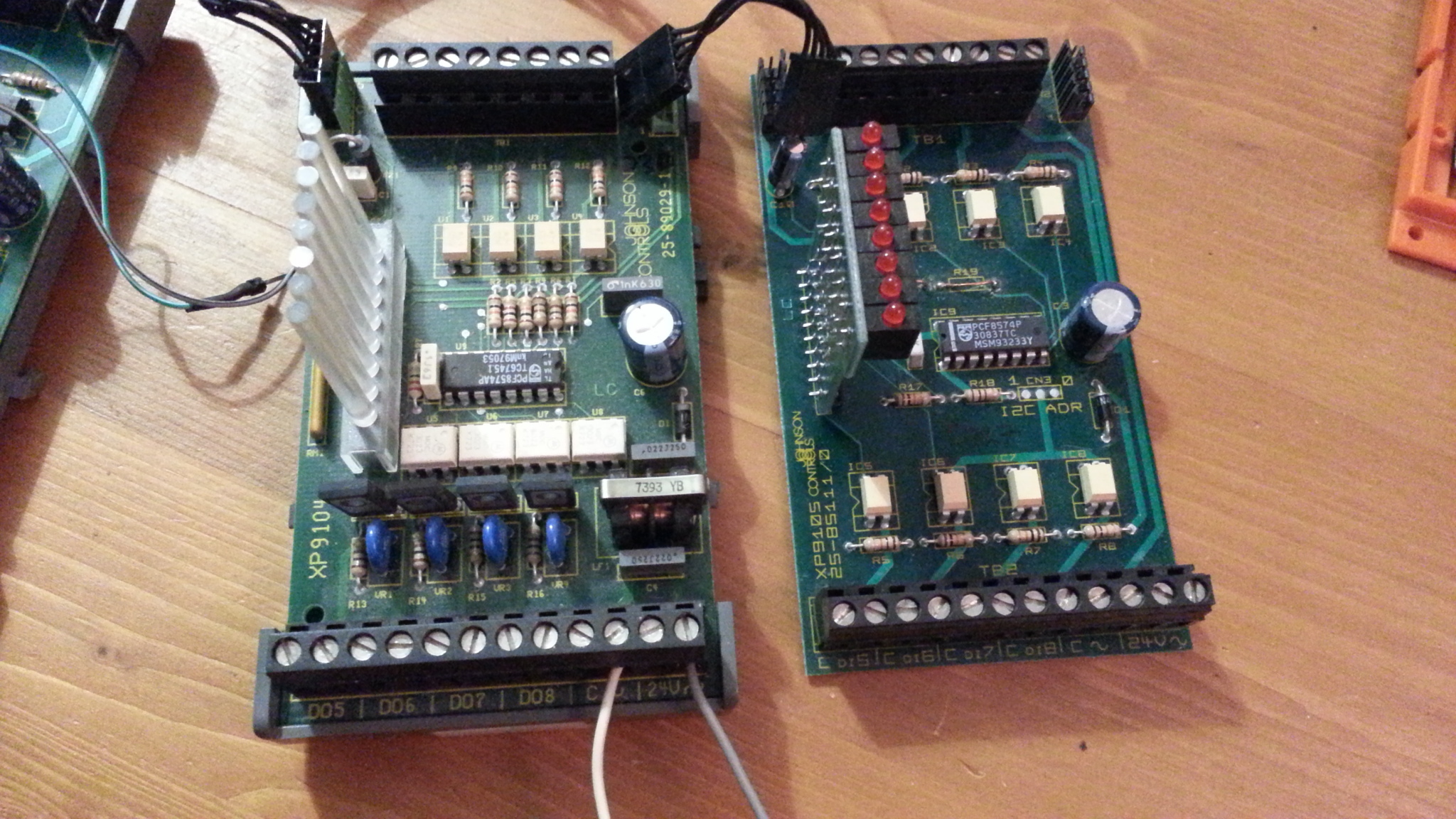
if not for the Arduino sketch, and its functionning with the PCF8574 library from RobT it's functional :)
as soon as I activate
#define MY_TRANSPORT_WAIT_READY_MS 3000
it works, why it works :(Thank you jkandasa for your curiosity, yes the fact that I dive back into it there was like a spark inter neuronal :)
Thanks
-
in this sketch there is only the Mysensors library to call, to test
I just have to finalize my sketch and it to MyController
/************************************************************************************ Using an Arduino Uno or an ESP8266 on NodeMCU to control buttons and relays through a PCF8574 GPIO expander. Requires the PCF8574 library https://github.com/RobTillaart/Arduino/tree/master/libraries/PCF8574 If using Uno, comment out #define intPin D4 If using ESP8266, comment out #define intPin 2 GPIO expander pinout: 0..3 = button input 0..3 4..7 = relay output 0..3 Each button controls a corresponding relay eg. button 0 controls relay 0 Button functions: button 0 and 1 toggle relay 0 and 1 on each press button 2 and 3 directly control relay 2 and 3 in "realtime" Gadget Reboot *************************************************************************************/ /* * DESCRIPTION : Arduino UNO et JC-PCF8574 pour 4 Input et 4 Relay * pour MySensors RS485 * * Libraries: PCF8574 de Rob Tillaart * * Modif/Afaire: * -o- * -x- * -o- * (x%) de l'espace de stockage de programmes * */ //----------- 2022 ------ PCF8574_RobTi_MyS_4io.ino ---------- test -----------------// //--------------- MyS --------------------------------- #define MY_DEBUG /*Enable debug prints to serial monitor*/ #define MY_DEBUG_OTA_DISABLE_ECHO //testing #define MY_TRANSPORT_WAIT_READY_MS 3000 #define MY_NODE_ID 40 /*Node en ID static*/ #define MY_RADIO_RF24 #include <MySensors.h> //---------------- PCF ------------------------------- #include <PCF8574.h> #include <Wire.h> PCF8574 pcf8574(0x3D); #define intPin 3 // interrupt input Uno volatile bool buttonPressed = false; // button interrupt flag byte buttonReg; // button read register //----------------- SETUP ------------------------- void setup() { //initialize PCF8574 with an interrupt pin and set all outputs to '1' (Relays off) Wire.begin(); pinMode(intPin, INPUT_PULLUP); attachInterrupt(digitalPinToInterrupt(intPin), buttonISR, FALLING); pcf8574.begin(0xFF); // turn off all Relays } //----------------- LOOP ---------------------------- void loop() { // if a button press was detected via interrupt, check if the button press // occurred on one of the "toggle" control buttons and toggle the relay if so if (buttonPressed) { delay(50); // crude debounce buttonReg = pcf8574.read8(); if (!bitRead(buttonReg, 0)) { //toggle a relay if button pressed pcf8574.toggle(4); } if (!bitRead(buttonReg, 1)) { //toggle a relay if button pressed pcf8574.toggle(5); } } buttonPressed = false; // clear interrupt flag // manually poll last two buttons and set relays to match button on/off realtime state // method 1: read all buttons and choose the desired button from the read register // buttonReg = pcf8574.read8(); // pcf8574.write(6, bitRead(buttonReg, 2)); // method 2: directly read just one button and directly set the target relay pcf8574.write(7, pcf8574.read(3)); pcf8574.write(6, pcf8574.read(2)); } //---- interrupt service routine ------------ void buttonISR() { buttonPressed = true; } //------------------------------ End pgm ------------------------------------- -
Operation Expander success
I show you two sketches, still based on Rob Tillaart library.
-
the 1st one is a basic version without MySensors
(to understand how the library works)
an Input (a shunt) controls an Output.
4 inputs 4 outputs -
the 2nd one is with MySensors, everything goes up well on MyController, and the 1st time :) (I am surprised :) )
a request, a hand for the 2nd for a "clean" touch up of the code (or errors to remove ?? )
Yes code readable for beginners, simple function.after cella another video
Thanks and good night
/* * Test PCF8574 avec module Metasys JC / 4di 4do - 0X03D i2c adress * * DESCRIPTION : Exemple pour lire 4 entrée et contrôler 4 Relais * avec un PCF8574 (la commande et par les 4 entrée) * * LIBRAIRIES: * - Rob Tillaart pour PCF8574 https://github.com/RobTillaart/Arduino/tree/master/libraries/PCF8574 * * ELEMENTS: * Do : ? - Digital output / Relay * * Modification: * -x- * -o- * -o- * * */ //-----------2022---------------- PCF8574 / 4DI-4DO - JC -----------------// #include "PCF8574.h" PCF8574 PCF27a (0x3D); //---------------- SETUP ------------------------- void setup() { Serial.begin(115200); //--------- testing IsConnected i2c PCfx ------------ Serial.println(__FILE__); Serial.print("PCF8574_LIB_VERSION:\t"); Serial.println(PCF8574_LIB_VERSION); if (!PCF27a.begin()) { Serial.println("could not initialize..."); } if (!PCF27a.isConnected()) { Serial.println("=> not connected"); } else { Serial.println("=> connected!!"); } } //----------------- LOOP ---------------------------- void loop() { if (PCF27a.read(0) == LOW) do4High(); else PCF27a.write(4, HIGH) ; if (PCF27a.read(1) == LOW) do5High(); else PCF27a.write(5, HIGH) ; if (PCF27a.read(2) == LOW) do6High(); else PCF27a.write(6, HIGH) ; if (PCF27a.read(3) == LOW) do7High(); else PCF27a.write(7, HIGH) ; } // ------- 4x Relay ON ---------- void do4High() { PCF27a.write(4, LOW); } void do5High() { PCF27a.write(5, LOW); } void do6High() { PCF27a.write(6, LOW); } void do7High() { PCF27a.write(7, LOW); } //------------------------------ End pgm ------------------------------------- -
-
/* * Test PCF8574 avec module Metasys JC / 4di 4do - 0X03D i2c adress * * DESCRIPTION : Exemple pour lire 4 entrée et contrôler 4 Relais * avec un PCF8574 (la commande et par les 4 entrée) * * LIBRAIRIES: * - Rob Tillaart pour PCF8574 https://github.com/RobTillaart/Arduino/tree/master/libraries/PCF8574 * * ELEMENTS: * Do : ? - Digital output / Relay * * Modification: * -x- * -o- * -o- * * (14%) de l'espace de stockage de programmes */ //-----------2022---------------- PCF8574 / 4DI-4DO - MyS et MyC -----------------// //--------------- MyS --------------------------------- //#define MY_DEBUG /*Enable debug prints to serial monitor*/ //#define MY_DEBUG_OTA_DISABLE_ECHO //testing #define MY_TRANSPORT_WAIT_READY_MS 3000 /*Tempo de mis en Com (millisecondes) à placer avant Mysensors.h*/ #define MY_NODE_ID 40 /*Node en ID static*/ /* ----- Module TTL-RS485 ----*/ #define MY_RS485 /*Apl du transport RS485 (protocol?)*/ #define MY_RS485_DE_PIN 2 /*Cmd DE pin*/ #define MY_RS485_BAUD_RATE 9600 /*Set RS485 baud rate to use*/ #define MY_REPEATER_FEATURE /*Activer fonctionnalité de répéteur du nœud*/ #include <MySensors.h> //---------------- PCF ------------------------------- #include "PCF8574.h" PCF8574 PCF27a (0x3D); // adjust addresses i2c pcf8574 // ------ objet ------ #define CHILD_ID_B0 0 /*Id IN - bp */ #define CHILD_ID_R4 4 /*Id OUT - relay */ #define RELAY_ON 1 #define RELAY_OFF 0 int oldValue0=-1; // input bp //---------- MyS ------------- MyMessage msg0(CHILD_ID_B0,V_TRIPPED); /*Boton*/ MyMessage msg4(CHILD_ID_R4,V_STATUS); /*Relay*/ bool info; // pour info GW sur MyC bool state = false; //---------------- SETUP ------------------------- void setup() { //Serial.begin(115200); //--------- testing IsConnected i2c PCfx ------------ Serial.println(__FILE__); Serial.print("PCF8574_LIB_VERSION:\t"); Serial.println(PCF8574_LIB_VERSION); if (!PCF27a.begin()) { Serial.println("could not initialize..."); } if (!PCF27a.isConnected()) { Serial.println("=> not connected"); } else { Serial.println("=> connected!!"); } PCF27a.begin(0xFF); // turn off all Relays ???? // ---- info send to gateway ---- send(msg0.set(info)); send(msg4.set(info)); } //----------------- MyS ---------------------------- void presentation() { sendSketchInfo("DiDo node 40", "2.0"); /*info version sketch à la passerelle*/ /*Mysenors Enregistre Child sur la Gw*/ present(CHILD_ID_B0, S_DOOR, "boton"); /*Boton*/ present(CHILD_ID_R4, S_BINARY, "relay"); /*Relay*/ /* requetes/demandes à un noeud ou GW une variable*/ request(CHILD_ID_B0, V_STATUS); /*Boton*/ request(CHILD_ID_R4, V_STATUS); /*Relay*/ // metric = getControllerConfig().isMetric; } //----------------- LOOP ---------------------------- void loop() { /* ------ MyS input -----------------------*/ int value0 = PCF27a.read(0); if (value0 != oldValue0) { send(msg0.set(value0==HIGH ? 1 : 0)); // Envoyer la nouvelle valeur oldValue0 = value0; } } //--------- MyS out ---------------------------- void receive(const MyMessage &message) { if (message.getType()==V_STATUS) { // Change relay state state = (bool)message.getInt(); PCF27a.write(4, state?RELAY_ON:RELAY_OFF); send(msg4.set(state?RELAY_ON:RELAY_OFF)); } } //------------------------------ End pgm ------------------------------------- -
Hello
a request for information.
What value should be given to avoid a difference in the on/off states between the visualization on the controller and the reality on the LEDs of the Expander module?- on the Arduino's Mysensors sketch
- on the configuration of the Field of MyController
on which feet to start ????
Another question, how to have the synchronicity of the state of the physical outputs (relays/led) and the view on MyC ???
with this version of the sketch the state of the outputs is well to go back to the controller after reboot of the Node
void receive(const MyMessage &message) {
   if (message.getType()==V_STATUS) {
    // Change relay state
    state = (bool)message.getInt();
     PCF27a.write(4,  state?RELAY_ON:RELAY_OFF);
    send(msg4.set(state?RELAY_ON:RELAY_OFF))
but now with this version, the reality is false
(an augmented reality :) )void receive(const MyMessage &message) { if (message.getType()==V_STATUS) { switch (message.sensor) { case 4: state = message.getBool(); PCF27a.write(4, state?RELAY_ON:RELAY_OFF); break;the function
// send(msg4.set(PCF27a.read(4)));is removed and you can't see how to add it
merci
-
here is a small truth table for the state of the input/output and the values to give to MyController
#define RELAY_ON 0        //  1 reversal of values
  #define RELAY_OFF 1    //  0
now only the MyS states to be sent to MyC to find.
I stop my dialogue :)
-
final sketch and functional with MyController
/*
 *  DESCRIPTION : 4 inputs and 4 outputs on i2C bus with a PCF8574
 *
 *  LIBRAIRIES:
 *    - Rob Tillaart pour PCF8574 https://github.com/RobTillaart/Arduino/tree/master/libraries/PCF8574
 *    - MySensors / Arduino Uno    https://github.com/mysensors/MySensors
 *
 *  ELEMENTS:
 *    - Expander PCF8574 avec module Metasys JC / 4di 4do - 0X03D i2c adress
 *
 *  MODIFICATION:
 *    -x- RAS : Fonctionnelle
 *    -o-
 *    -o-
 *
 *     (36%) de l'espace de stockage de programmes
*/

   //----------- 9 Mai 2022 ---------------- PCF8574 -4DI-4DO / MyS RS485 et MyC -----------------//


//------------------- MyS ---------------------------------
  //#define MY_DEBUG               /*Enable debug prints to serial monitor*/
  //#define   MY_DEBUG_OTA_DISABLE_ECHO //testing
  #define MY_TRANSPORT_WAIT_READY_MS 3000 /*Tempo de mis en Com (millisecondes) à placer avant Mysensors.h*/
  #define MY_NODE_ID 40          /*Node en ID static*/

/* ----- Module TTL-RS485 ----*/
  #define MY_RS485                  /*Apl du transport RS485 (protocol?)*/
  #define MY_RS485_DE_PIN 10         /*Cmd DE pin*/
  #define MY_RS485_BAUD_RATE 9600   /*Set RS485 baud rate to use*/
  #define MY_REPEATER_FEATURE       /*Activer fonctionnalité de répéteur du nœud*/

  #include <MySensors.h>

//---------------- PCF -------------------------------
  #include "PCF8574.h"
  PCF8574 PCF27a (0x3D);  // adjust addresses i2c pcf8574

// ------ objet ------
  #define CHILD_ID_B0 0    /*Id IN - bp */
   #define CHILD_ID_B1 1
    #define CHILD_ID_B2 2
     #define CHILD_ID_B3 3
  #define CHILD_ID_R4 4    /*Id OUT - relay */
   #define CHILD_ID_R5 5
    #define CHILD_ID_R6 6
     #define CHILD_ID_R7 7

  #define RELAY_ON 0    //  1  valeur
  #define RELAY_OFF 1    // 0  invers

//---------- MyS -------------

  MyMessage msg0(CHILD_ID_B0,V_TRIPPED);  /*Boton*/
   MyMessage msg1(CHILD_ID_B1,V_TRIPPED);
    MyMessage msg2(CHILD_ID_B2,V_TRIPPED);
     MyMessage msg3(CHILD_ID_B3,V_TRIPPED);

  MyMessage msg4(CHILD_ID_R4,V_STATUS);   /*Relay*/
   MyMessage msg5(CHILD_ID_R5,V_STATUS);
    MyMessage msg6(CHILD_ID_R6,V_STATUS);
     MyMessage msg7(CHILD_ID_R7,V_STATUS);

    bool info;              // pour info GW sur MyC
    bool state = false;     // output
  //  bool state4 = false;  bool state5 = false;  bool state6 = false;  bool state7 = false;
    int oldValue0=-1; int oldValue1=-1; int oldValue2=-1; int oldValue3=-1;  // Input

//---------------- SETUP -------------------------
 void setup() {

 // Serial.begin(115200); // debug

//--------- testing IsConnected i2c PCfx ------------
  Serial.println(__FILE__);
  Serial.print("PCF8574_LIB_VERSION:\t");
  Serial.println(PCF8574_LIB_VERSION);

  if (!PCF27a.begin())   {
    Serial.println("could not initialize...");
    }
  if (!PCF27a.isConnected())   {
    Serial.println("=> not connected");
    }
    else   {
    Serial.println("=> connected!!");
    }

    // ---- info send to gateway ----
  send(msg0.set(info)); send(msg1.set(info)); //input
  wait(200);
  send(msg2.set(info)); send(msg3.set(info));  //input

  wait(200); //delays for frames, depending on system load and bus type (wireless or wired)

  send(msg4.set(info)); send(msg5.set(info));   //output
  wait(200);
  send(msg6.set(info)); send(msg7.set(info));  //output
  }

//----------------- MyS ----------------------------
void presentation() {

  sendSketchInfo("PCF8574 x4in/out - node40", "2.0");  /*info version sketch*/

/*Mysenors Enregistre Child sur la Gw*/
  present(CHILD_ID_B0, S_DOOR, "boton0");      /*Boton*/
  present(CHILD_ID_B1, S_DOOR, "boton1");
  wait(200);
  present(CHILD_ID_B2, S_DOOR, "boton2");
  present(CHILD_ID_B3, S_DOOR, "boton3");

  wait(200); //delays for frames, depending on system load and bus type (wireless or wired)

  present(CHILD_ID_R4, S_BINARY, "relay4");    /*Relay*/
  present(CHILD_ID_R5, S_BINARY, "relay5");
  wait(200);
  present(CHILD_ID_R6, S_BINARY, "relay6");
  present(CHILD_ID_R7, S_BINARY, "relay7");

  wait(200);

  // metric = getControllerConfig().isMetric;
  }

//----------------- LOOP ----------------------------
 void loop() {

//----------- MyS input -------------------------------
   int value0 = PCF27a.read(0);
   if (value0 != oldValue0) {
     send(msg0.set(value0==HIGH ? 1 : 0));   //Send new value
     oldValue0 = value0;
  }

   int value1 = PCF27a.read(1);
   if (value1 != oldValue1) {
     send(msg1.set(value1==HIGH ? 1 : 0));
     oldValue1 = value1;
  }

   int value2 = PCF27a.read(2);
   if (value2 != oldValue2) {
     send(msg2.set(value2==HIGH ? 1 : 0));
     oldValue2 = value2;
  }

   int value3 = PCF27a.read(3);
   if (value3 != oldValue3) {
     send(msg3.set(value3==HIGH ? 1 : 0));
     oldValue3 = value3;
  }

 }

//----------- MyS out -------------------------------
  void receive(const MyMessage &message) {

        if (message.getType()==V_STATUS) {

   switch (message.sensor) {
      case 4:
            state= message.getBool();
            PCF27a.write(4,  state?RELAY_ON:RELAY_OFF);
            break;
      case 5:
            state = message.getBool();
            PCF27a.write(5,  state?RELAY_ON:RELAY_OFF);
            break;
      case 6:
            state = message.getBool();
            PCF27a.write(6,  state?RELAY_ON:RELAY_OFF);
            break;
      case 7:
            state = message.getBool();
            PCF27a.write(7,  state?RELAY_ON:RELAY_OFF);
            break;
            }
         }
      }

//------------------------------ End pgm -------------------------------------
Hello! It looks like you're interested in this conversation, but you don't have an account yet.
Getting fed up of having to scroll through the same posts each visit? When you register for an account, you'll always come back to exactly where you were before, and choose to be notified of new replies (either via email, or push notification). You'll also be able to save bookmarks and upvote posts to show your appreciation to other community members.
With your input, this post could be even better 💗
Register Login