Efficiency of Voltage Boosters
-
@Yveaux As mentioned I am still learning about this stuff.
The question I have right now is, a bit off topic, at which pin do you measure this?
Is that simply vcc on the radio? -
@marceltrapman You're welcome :)
I tried 220µF myself now (EU keyoard can write µ with alt-gr+m or (ctrl+alt m if alt+gr is missing))
much better, I first used 33µF and then 100µF but 220µF is a winner.
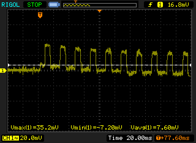
The wierd thing is that I cant measure any difference with 33µF or 220µF with my oscilloscope. but with no cap at all my arduino nano 3.3v looks like this: (AC coupled)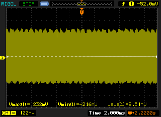
And wit cap (33µF or 220µF makes no difference at all..) But it works much better..
@Damme said:
much better, I first used 33µF and then 100µF but 220µF is a winner.
The wierd thing is that I cant measure any difference with 33µF or 220µF with my oscilloscope.So I think you are saying that you are not seeing a visual difference (on the o'scope) between 33uF and 220uF, but you are seeing better real world performance with the latter?
Do the different capacitors have the same spec's? I'm wondering if the capacity is the only significant change, or if the different values of cap you tested have different specs (eg: ESR) or even diff technology.
-
@Damme said:
much better, I first used 33µF and then 100µF but 220µF is a winner.
The wierd thing is that I cant measure any difference with 33µF or 220µF with my oscilloscope.So I think you are saying that you are not seeing a visual difference (on the o'scope) between 33uF and 220uF, but you are seeing better real world performance with the latter?
Do the different capacitors have the same spec's? I'm wondering if the capacity is the only significant change, or if the different values of cap you tested have different specs (eg: ESR) or even diff technology.
@Zeph Exacly, I first used 3.3µf and there I see voltage drop. But almost no measurable difference with 33µF or 220µF. But I get less failed transmission with the larger cap.
They are all the same brand (some cheap Chinese unknown (to me) brand, "Chong" (yay!))
All 16v, and all electrolytic. I don't have any ESR meter, thinking of trying to measure it with oscilloscope and function generator.. (Or I'll just bu one :))I bought them from ebay in a large 1800pcs asorted pack.
-
New data on the XC9140A331 3.3 V voltage booster. This looks like a nice IC with low quiescent current and an improvement over the stock "china" 3.3 V booster.
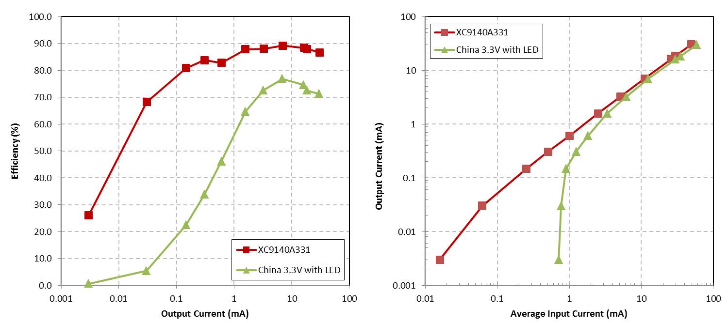
This option can be purchased from Digikey for $0.90, with a total bill of materials of $1.34 (in quantity, minus a PCB). It is also a nice size SOT23-5, not too small to hand solder.
Thoughts?
-
New data on the XC9140A331 3.3 V voltage booster. This looks like a nice IC with low quiescent current and an improvement over the stock "china" 3.3 V booster.
This option can be purchased from Digikey for $0.90, with a total bill of materials of $1.34 (in quantity, minus a PCB). It is also a nice size SOT23-5, not too small to hand solder.
Thoughts?
-
I look forward to a test of the TPS61222 used in the MySensors Battery board - I see the chip on your list and hope you will be checking it.
Felix at lowpowerlab (http://lowpowerlab.com/blog/2014/06/08/powershield-r2-released/) has switched from the TPS61220 to the LTC3525 for stability reasons. That's a 5v chip, tho but maybe there's a related one as a contender.
-
Any news on this front?
Started looking at the LTC3525 as well, but it ended up being a bit more expensive than I had wanted (looking at Digikey it is basically the most expensive DC-DC step-up IC they stock). For the 3.3V version there is like one (1!) AliExpress seller that has them in any quantity. 10pcs $23 and I'm currently pondering that.
Like @Zeph said, both lowpowerlab and harizanov have switched to the LTC3525.
Btw. Found an Eagle pcb for the LTC3525 here:
https://github.com/meigrafd/boost_converterAnyone found any other IC? TPS61016? TPS61006? TPS61201? ISL9111? MAX1724? UCC3941?
Or is the good old TPS6122x still the best choice at the end of the day in terms of price / performance? Looking at AliExpress it is basically half the price of LTC3525. And they're both the same pesky small package.
Also, still completely in the dark when it comes to finding suitable inductors in particular (sourced from China). If you're willing to buy from Digikey et al sure, but if you're trying to cut some corners things get a lot harder.
-
I have designed a PCB shield for the pro-mini, radio, and various sensors based on the the XC9140 chip. I will be powering the radio directly from 2xAA batteries. Boards should be here any day now and I'll check out the design. The XC9140 is not a bad chip from what I can tell, and it is cheap from Digikey, see posts above for BOM.
-
@hek Can you update the website for the decoupling capacitor recommendation? I wasted a lot of time trying to figure out why I have a lot of lost ACKs with my voltage boosted sensor until I found this topic. This made the sensors cry for a new parent quite frequently and it kept them awake more than necessary.
I had about 35% ACK packet loss with the 4.7uF capacitor which went down to 0.5% with a 68uF one (though the data got through). I will try to buy an even bigger low ESR one to make it zero, but the 4.7uF definitely doesn't do a good job if the signal is actually dirty.
Ok, I'll could increase the recommendation to 47uF in the next update.
But i'm not sure which works best. A electrolytic low ESR or if it is good enough with a cheap ceramic variant. If someone has the time and/or the equipment I would really appreciate some research.
-
47uF is what it took for my setup to work properly. Mine are just run of the mill electrolytic.
-
The "Efficiency of Voltage Boosters" thread is full of useful info but has been sleeping for a year so this is an effort to bring it back to life again :-)
I have built a few battery powered sensors based on the 328P-PU running at 8MHz as well as 1 MHz. Batteries used are common NiMH size AA + cheap Chinese 3.3V step-up converters. Both the processor and the radio are powered from the 3.3V converter which I understand can be a bad practice. Still I decided to try because I did not want to tamper with the fuses/bootloader at this stage and luckily I have so far not experienced any of the here described connectivity problems.
More or less out of curiosity I made a few tests of this setup using different sizes of same brand electrolytic capacitors (nothing fancy, bought as a Velleman high-Q kit, labeled "made in Europe"). The results does not give more info than already available here but it helped me understand and hopefully can help others too.
For the test setup a 10µF is soldered to the radio pins and I can add another in parallel through a socket. The unit tested is also equipped with both a 3.3 and a 5V step-up. A photo of the setup as well as a few screen dumps from an oscilloscope are attached as a pdf (hope it works). Readings are taken using a 8 MHz chip programmed as a motion sensor and while the sensor is at rest.
Here is a short summary and a curve of same data:
10 µf dV 76 mV
10 + 22 µF dV 43 mV
10 + 47 µF dV 28 mV
10 + 100 µF dV 14 mV
10 + 220 µF dV 9 mV
10 + 470 µF dV 5 mV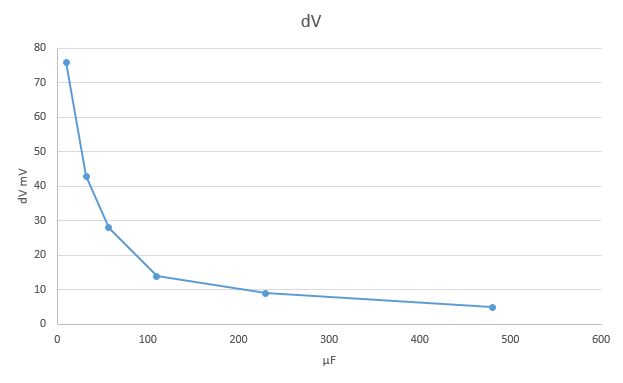
A bigger capacitor of course lower the amplitude of the ripple (not unexpected :-)) and the rapidly falling curve shows that the current recommendation of 47 µF is a good choice. Adding more will lower the ripple but not at all proportionally.
I am not experienced neither in building these battery powered sensors nor in measuring them why any comments/corrections will be appreciated.