Domoticz as controller **and** a gateway for MySensor nodes running on a Raspberry Pi 2
-
Just to let all know that I'm quite happy with my current setup: Domoticz as controller and a gateway running on a Raspberry Pi 2.
The serial gateway I use is made of a small board sitting on the GPIO pins of the same Raspberry.
The PCB for this gateway is public (https://oshpark.com/shared_projects/aXLXBO3f), the code to run is available from the Mysensors raspberry implementation. This creates a serial port which then needs to be represented via a symbolic link with a short name, so that Domoticz can see it.This allowed me to eliminate a physical gateway, since the raspberry runs as a gateway and a controller at the same time.
Many thank to the MySensors team for the sensor software (same shoutout to the Domoticz designers)

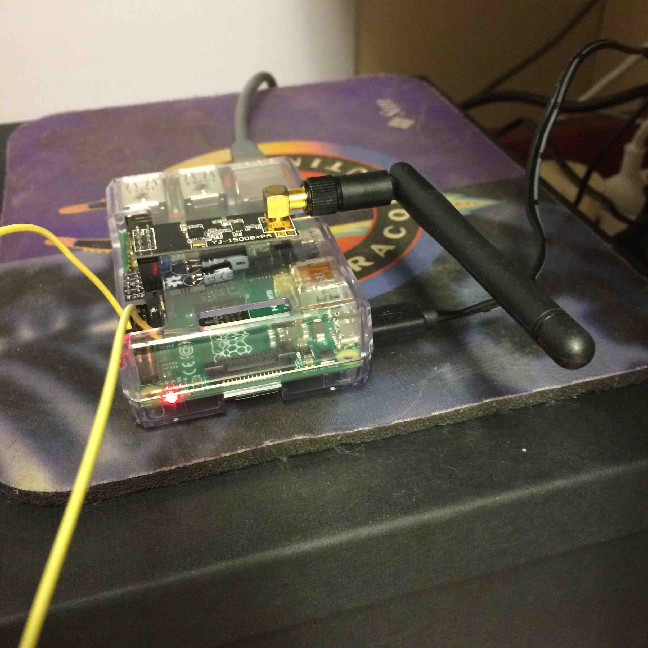
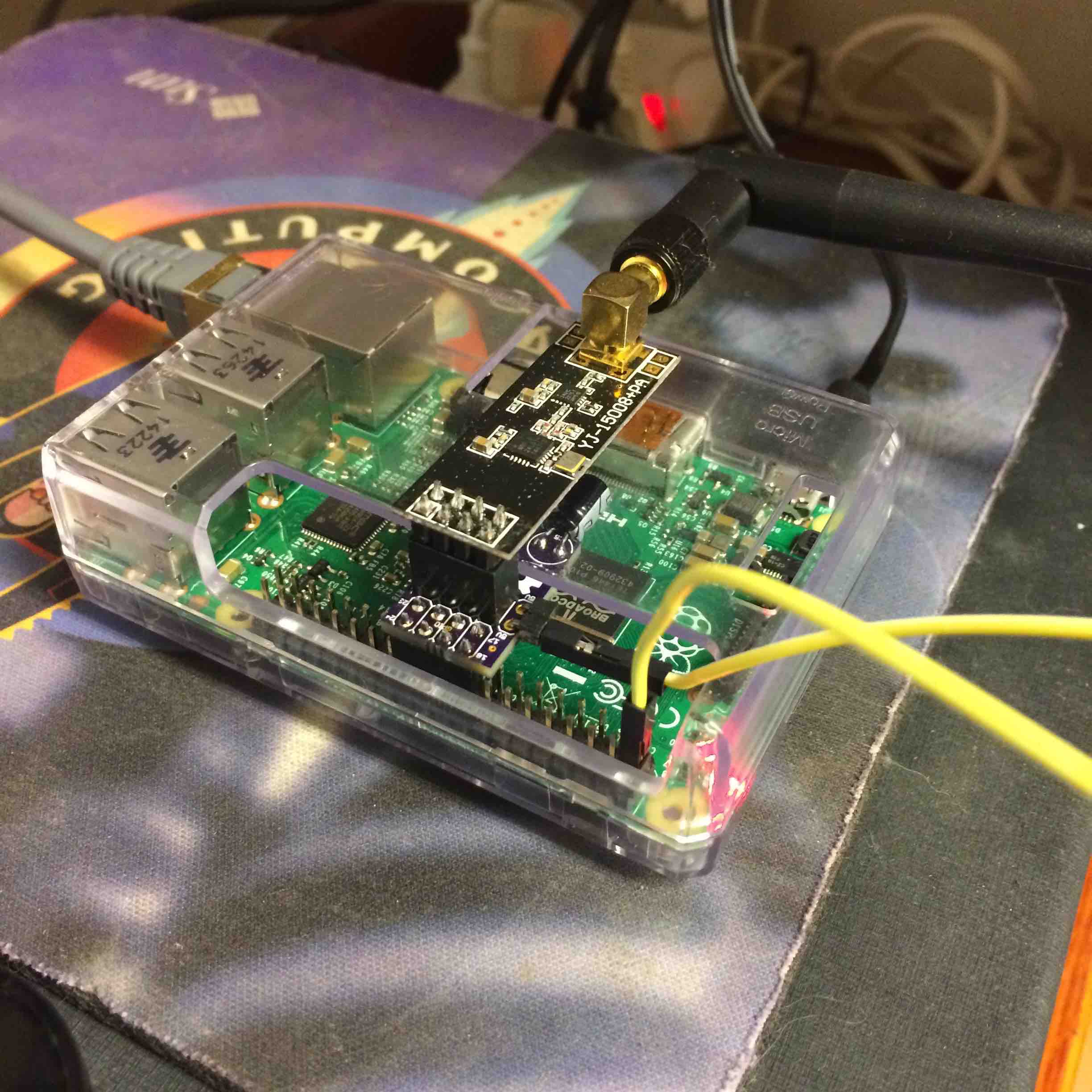
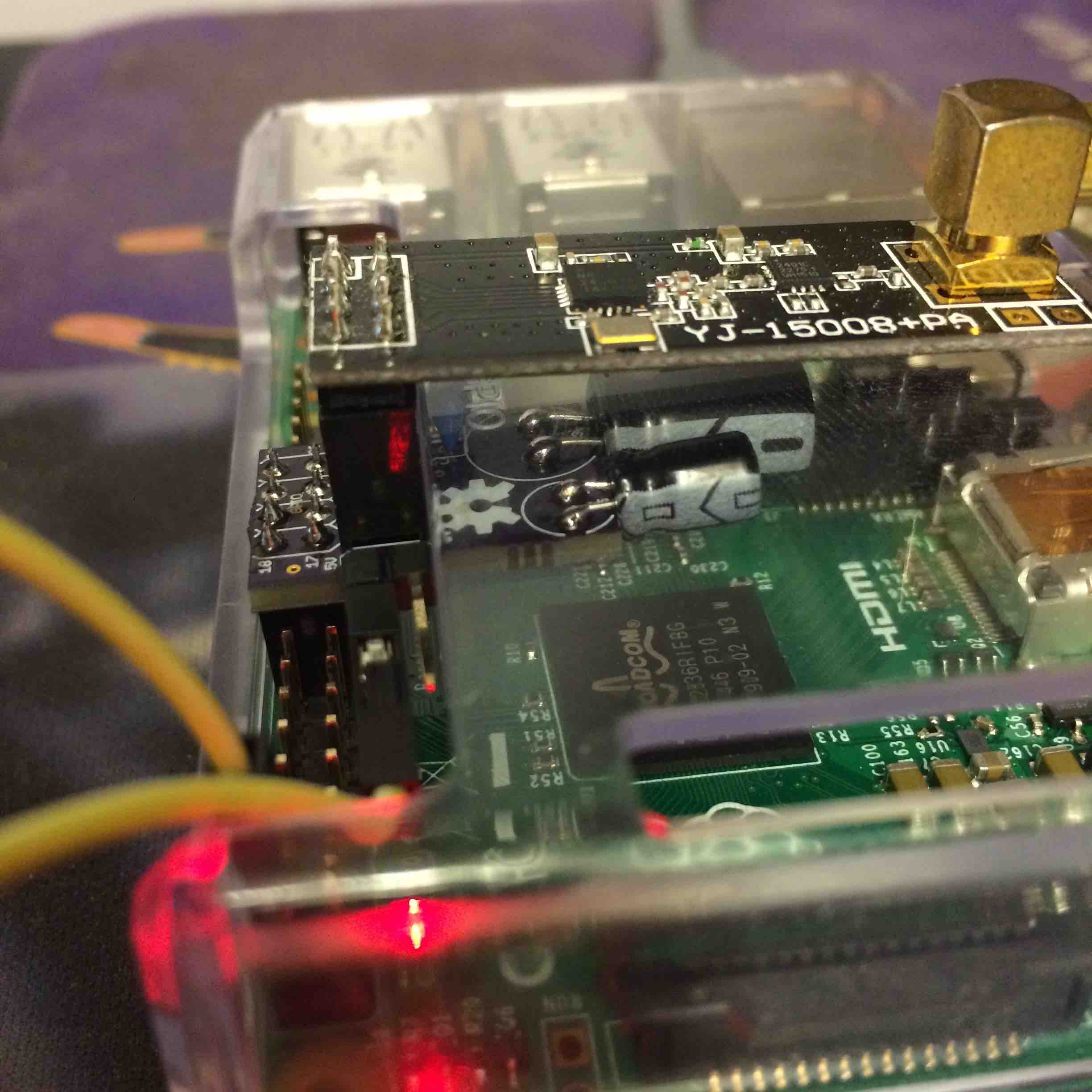

-
@GertSanders Nice project. Great work! (and that's some serious oldskool mousepad you've got there
 )
)
-
I was a teenager when the first Macintosh came out, being impressed it was faster then the LISA I had seen the year before. So yeah :-), I still have some old-school stuff laying around.
Going back to electronics and building stuff is super fun, made me remember why I wanted to be an electronics engineer in the first place. One tends to forget that after managerial jobs for many years. This site has given me inspiration for little projects I did not know I needed to do :-).
In any case, the tools to design and build, the option to realise those designs cheaply (e.g. OSHPark) are simple lightyears beyond what I had available in the eighties.
-
And for those interested: my design for a low power node is also available on OSHpark:
https://oshpark.com/shared_projects/qnkNIMZx
and it's companion (1 of many to come)
https://oshpark.com/shared_projects/IOHUNYT2
-
@GertSanders This looks really good, and will greatly simplify my set-up. I'm going to order the board from OSH Park - is there a list of components / instructions (I notice the board has solder jumpers)?
-
@MikeF:
There is 1 jumper to solder, and you need it to choose the power input towards the NRF24. If you bridge the middle with the 5V side, you need to connect 5V from the GPIO pins 2 or 4 (or both if you want) to one of the 5V pins on the small PCB using a wire (as you see in the images). This will feed the onboard powerregulator with 5V so that this one can give 3V3 to the radio.If you bridge middle with 3V3 side, then power is taken directly from the 3V3 pin on the GPIO and connected straight to the radio Vcc pin.
For the radio with external SMA antenna, you need to use the 5V from the Raspberry (actually directly from the USB source). The smaller NRF24's (without external antenna) do not need more power and the GPIO 3V3 pin (and Raspberry's 3V3 regulator) can deliver sufficient power.
I chose to use a small wire to connect the 5V, so that the cost of the board was low. OSHPark is nice for small series and cheap in the smaller sizes (certainly given the quality of PCB they deliver). Very sad that 5V is only presented on the edge of the GPIO. It would have been nicer to have at least one 5V pin with shorter distance from the SPI pins. I use my setup with the more powerful nrf24L01+ with SMA antenna, hence the "5V hack", but if one uses the smaller radios with antenna on the board, then no wire is needed since 3V3 is available within the connector.
The onboard power-regulator is a LM1117 at 3V3 fixed. I will add a few more pictures tonight.
Capacitors are 100nF, 10uF and 100uF respectively (ranging from small to large). The two larger capacitors are polarised electrolytic, the small one is a ceramic type.
Normally the electrolytic capacitors are to be mounted verticaly. In my case I soldered them sideways, so it would all fit within the raspberry case. But even vertically they stay under the radio board. The largest one may touch the bottom, so insulation needs to be put on top of the capacitor in that case I think, I will check.
-
This is interesting stuff! Do you know if the raspberrypi port supports rf69 as well?
-
@Anticimex: no idea. I have not used the RF69 so far. Still a lot to learn from the "classic" nrf24l01+ :-).
But if the same pins are used in the same location, then I believe it depends on the software. The SerialGateway software for Raspberry. Maybe one of the original designers of that gateway can tell you if they support RF69. Would be nice !
-
Here is an image of the voltage regulator I use:
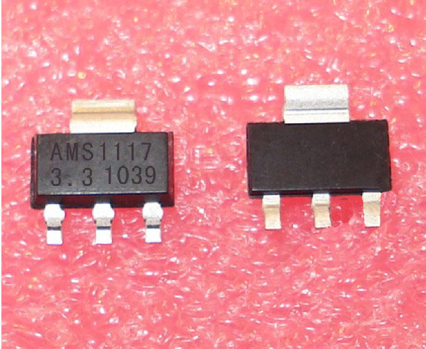
SOT223 package, more then powerful enough for a single SMA-type NRF24.
-
@GertSanders Thanks for the extra info - that was very helpful.
-
some more images
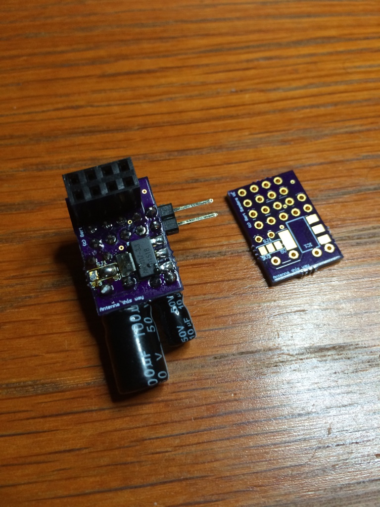
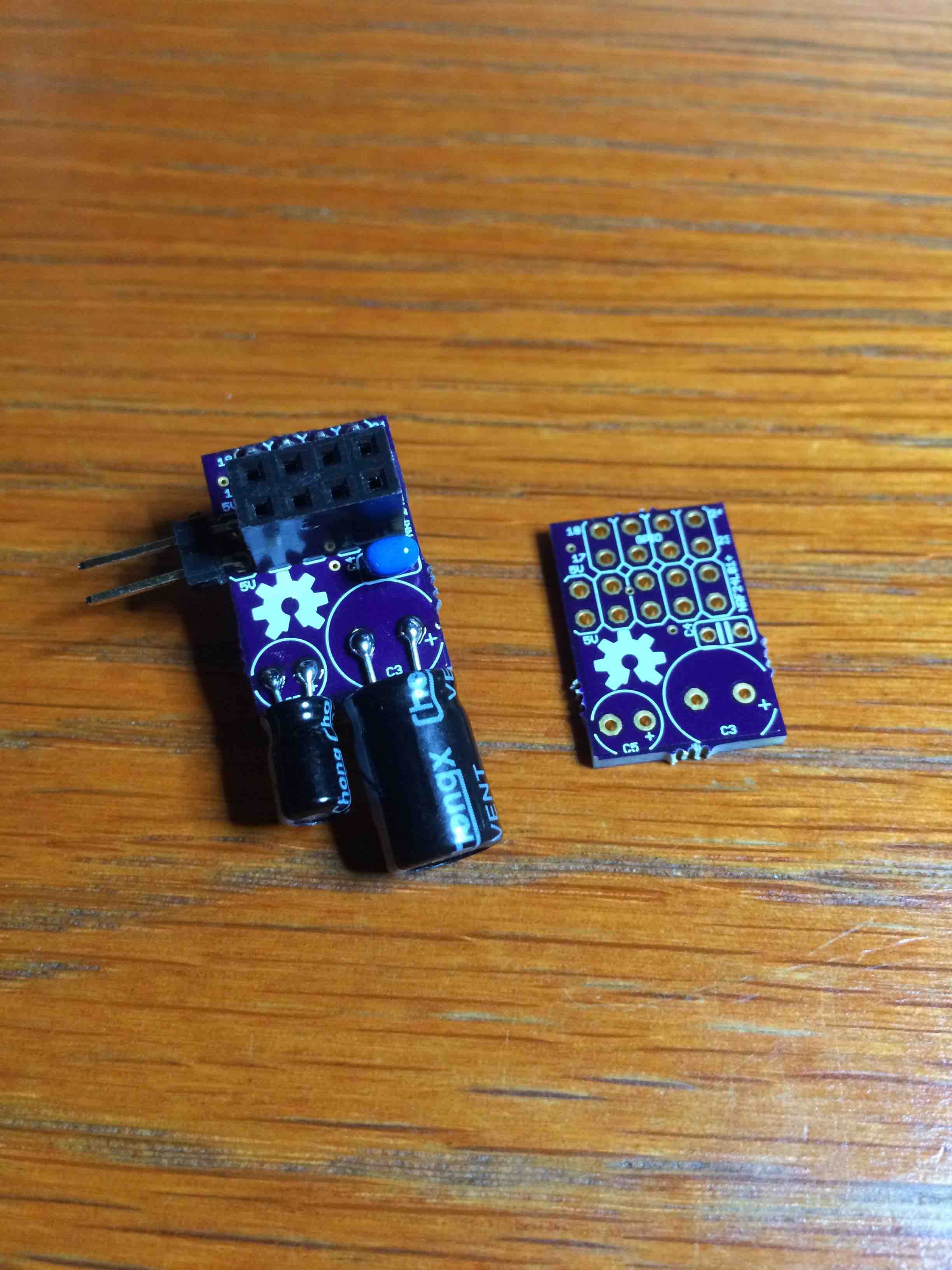
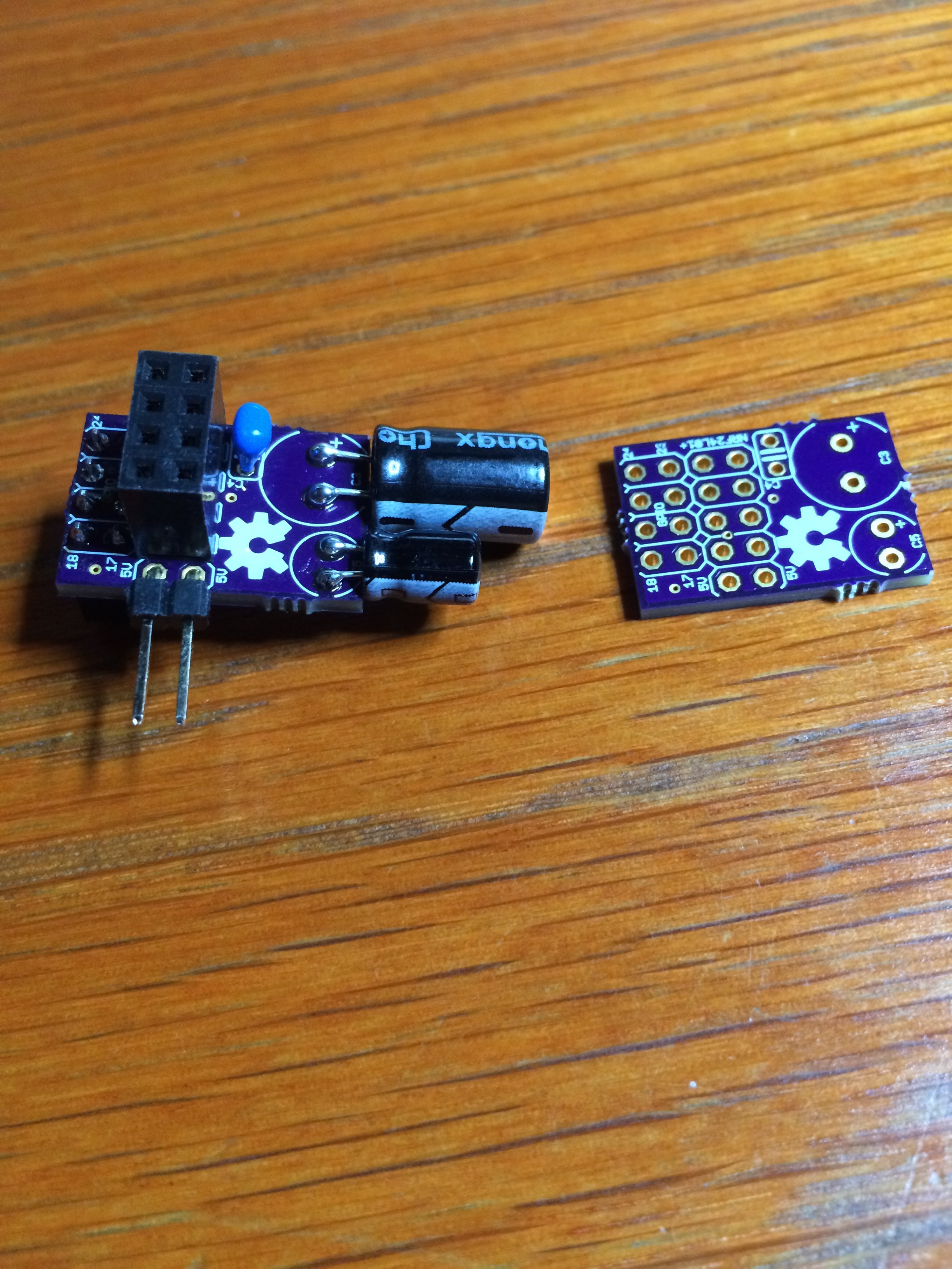
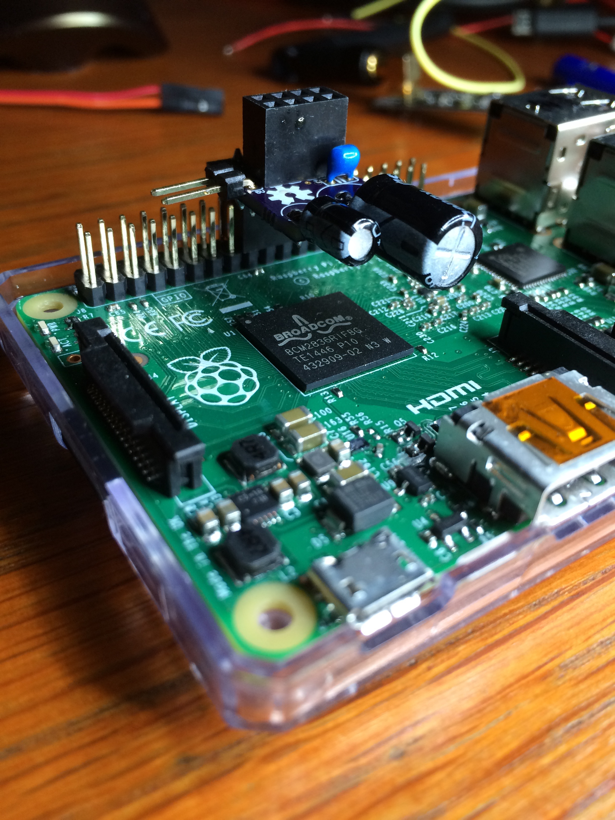
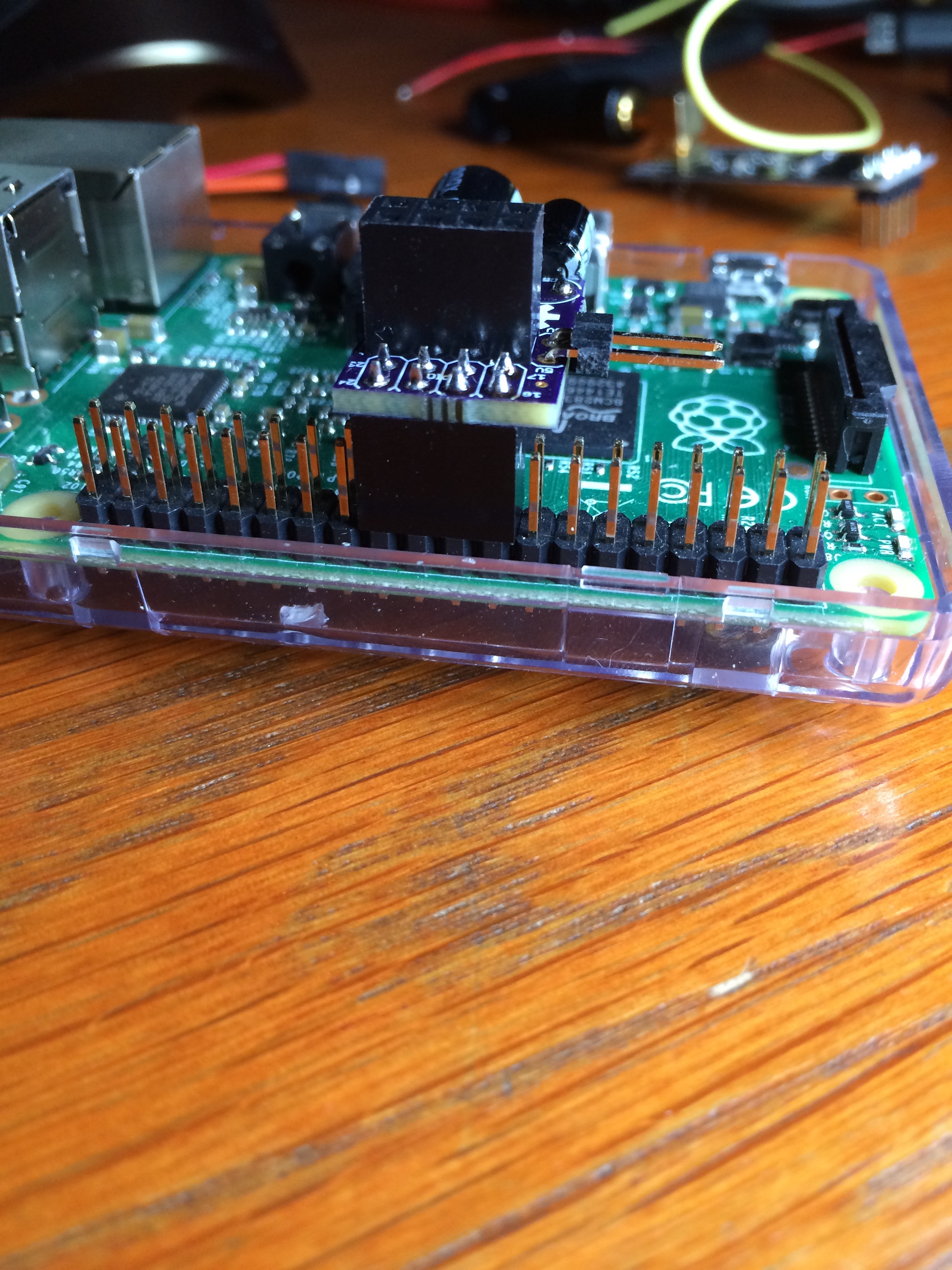
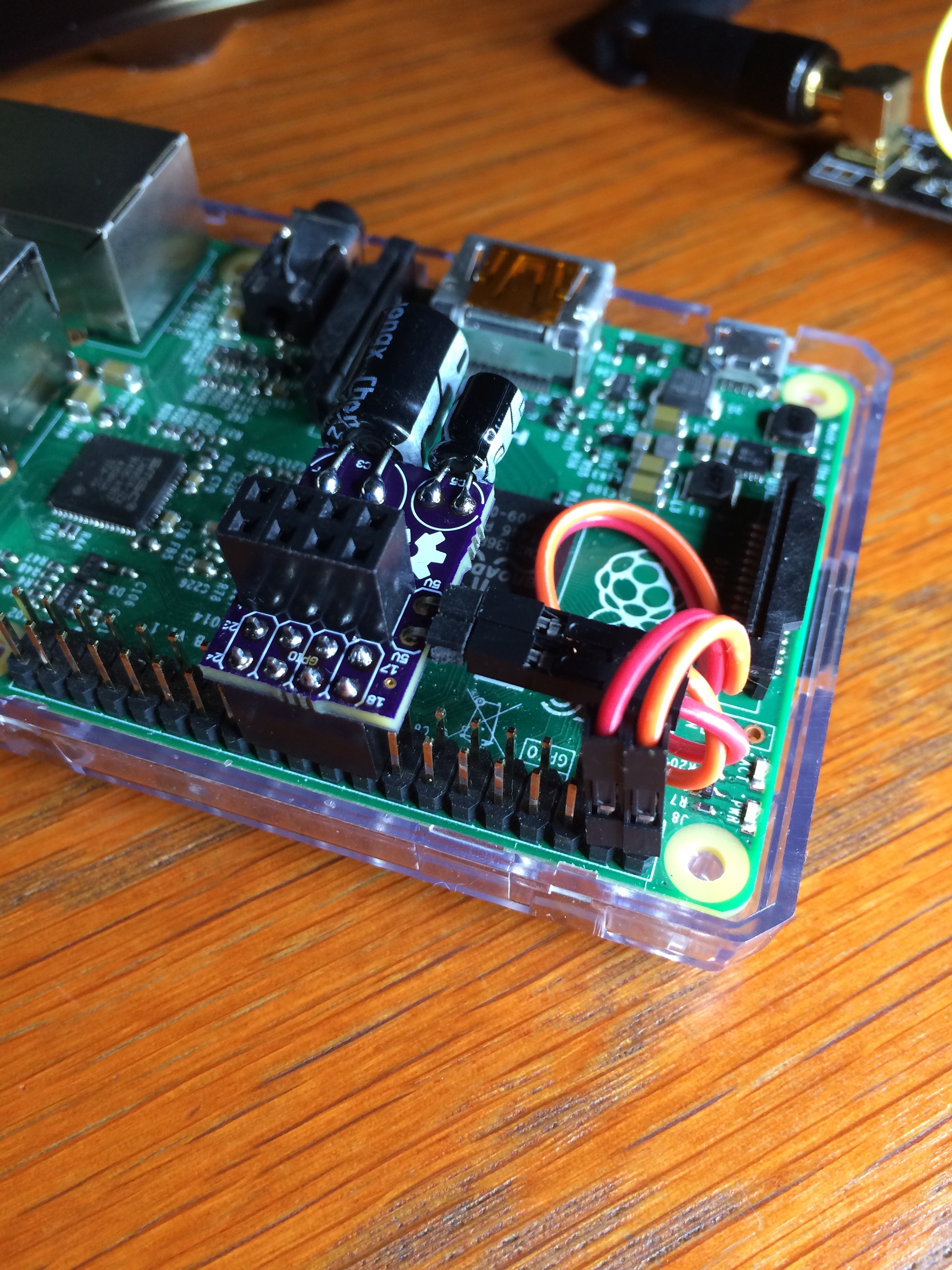
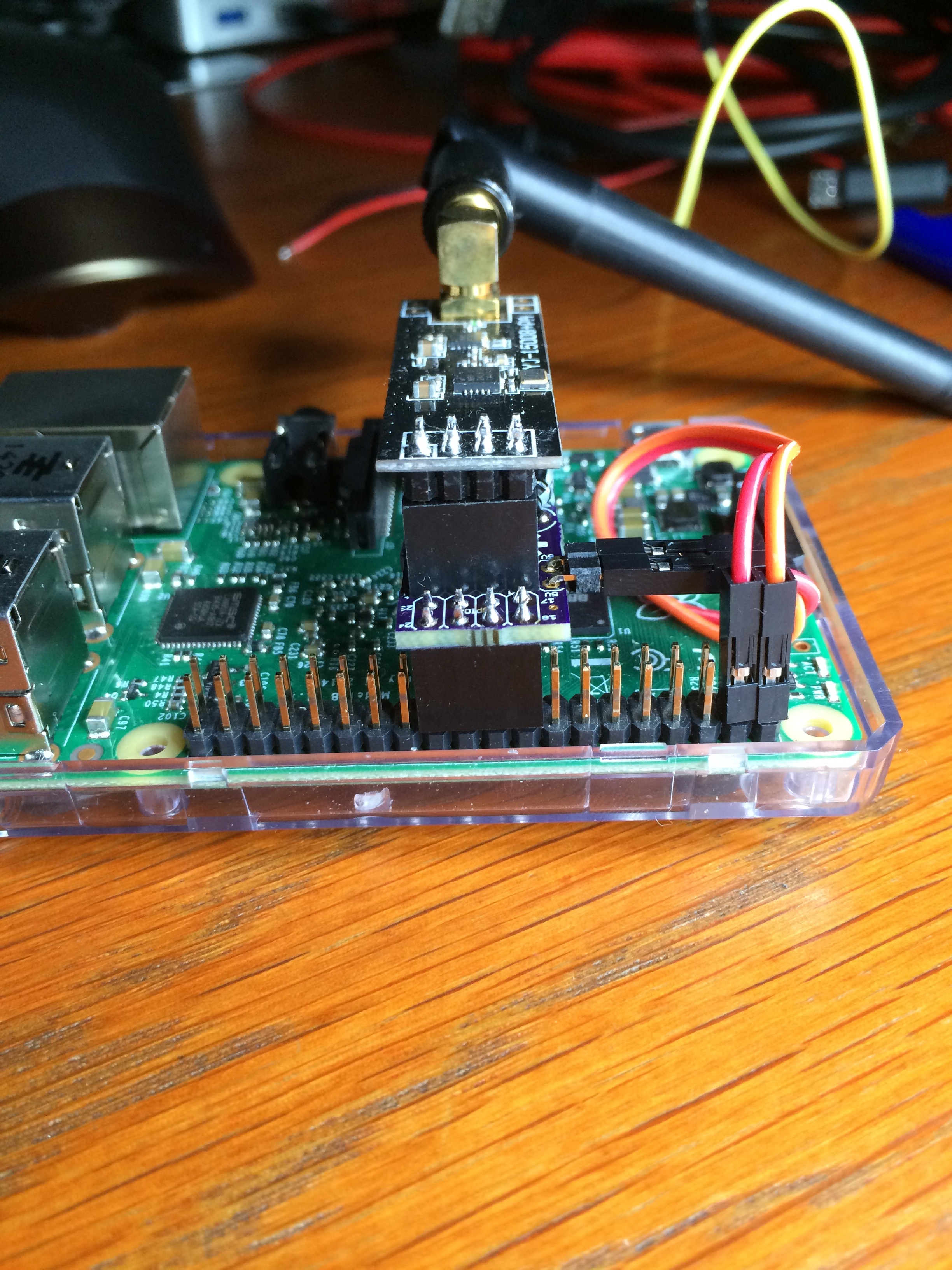
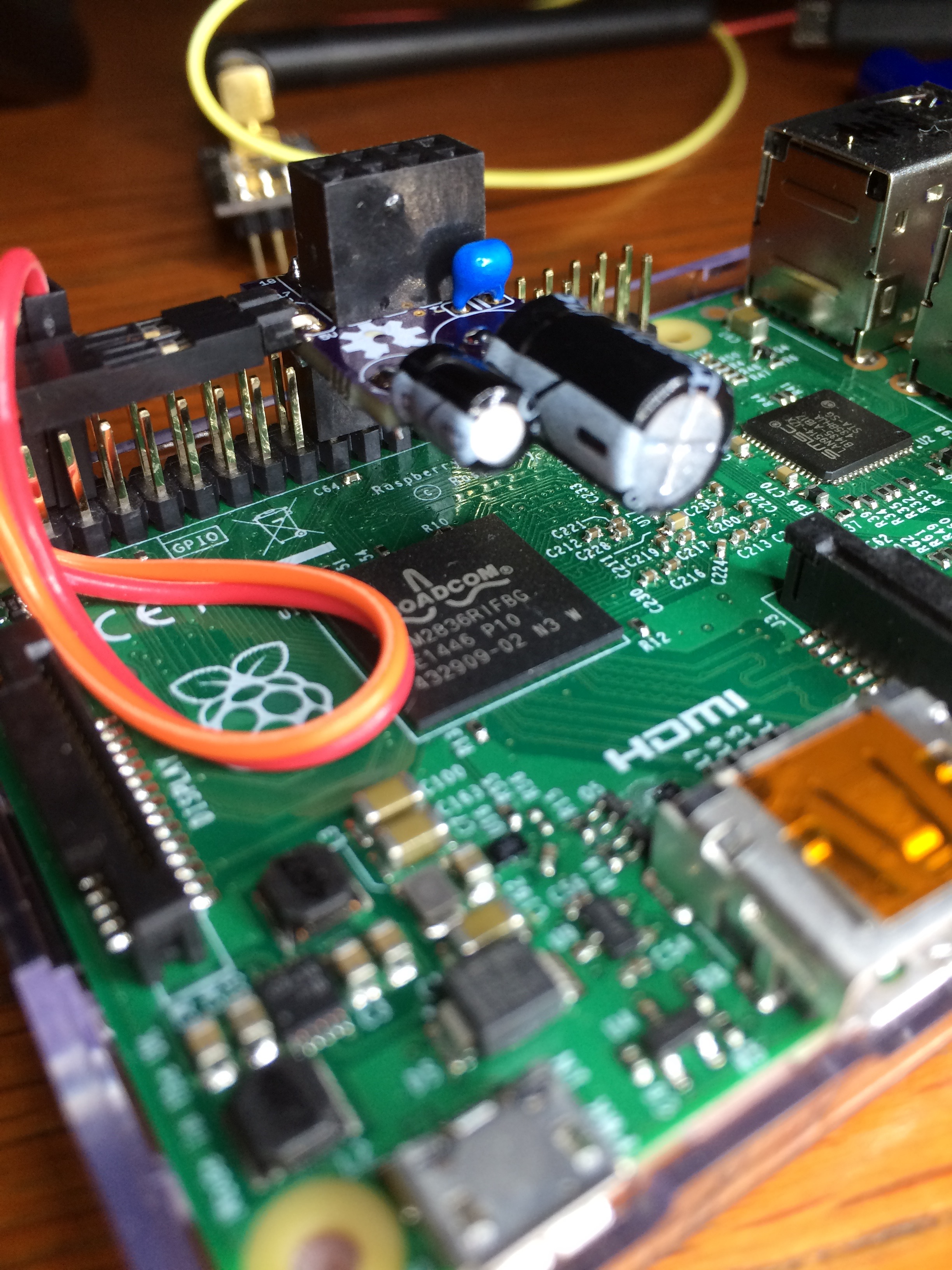
-
Hi @GertSanders, I've received the PCB, built the adaptor and the software as per the MySensors Raspberry Port GitHub. I've created a symlink to /dev/ttyMySensorsGateway (/dev/ttyUSB40), which Domoticz, and I see the following in the Domoticz log:
2015-09-29 17:48:40.503 MySensors: Using serial port: /dev/ttyUSB40
2015-09-29 17:48:40.503 MySensors: Gateway Ready...However, I can't see any of the devices on my node - any ideas?
-
In my case I had to restart the nodes, because they did not get the ID from Domoticz. But it takes a few minutes. The gateway is polled every 30 seconds or so. Apart from that, I do not know what could be the problem. Did you allow discovery/addition of new sensors in Domoticz ?
The board should sit between pin 17/18 and 23/24 of the GPIO. There is not much on the board that could malfunction, except maybe the power regulator. Does it give 3V3 ?
Did you solder the jumper right?
If you solder close to the regulator, the board expects connection to 5V (as in my pictures). If you connected the 3V3 side, then it takes power directly from the GPIO. With the large NRF24 that could be insufficient.If all fails, then test without the board: connect the radio directly to the GPIO. That is all I can think of without seeing your setup.
-
Thanks, Gert. I've checked all my soldering (continuity from header to header), the jumper is soldered for 5V, and I'm getting 3V3 across the supply pins of the radio. Board is sitting between 17/18 & 23/24.
I'm still only getting the above 2 lines in the log, i.e., no devices.
I'll try connecting the radio direct to the GPIO later today.
-
Cracked it! I'm using an RPi 2, and cat /proc/cpuinfo gives a01041 as hardware version. According to GitHub readme, CE needs to go to pin 15, not 22.
Now working with radio connected directly, but will now need to connect a jumper wire from the adaptor board.
-
Strange, I'm also working on the RPi 2. I will check what I have in my RF24 library, because I'm sure that you can change pin assignment in software instead of needing to resort to extra jumper wire.
When home I will check this tonight. I really need to write out a procedure for this, or we will forget in the future how it should be set up.
-
Hello @GertSanders, for the time being I've got the gateway working with CE connected to pin 15, having carried out some 'surgery' to the board!
I've found this code in PiGatewaySerial.cpp (line 198 onwards):
/* create MySensors Gateway object */
#ifdef __PI_BPLUS
gw = new MyGateway(RPI_BPLUS_GPIO_J8_15, RPI_BPLUS_GPIO_J8_24, BCM2835_SPI_SPEED_8MHZ, 1);
#else
gw = new MyGateway(RPI_V2_GPIO_P1_22, BCM2835_SPI_CS0, BCM2835_SPI_SPEED_8MHZ, 1);
#endifIs this the 'offending' code?
-
Yes, as the rpi2 is not recognised properly the code compiles for rpib+.
I changed the code so that both rpi b+ as rpi2 have the same: use pin 22
-
@MikeF said:
gw = new MyGateway(RPI_V2_GPIO_P1_22, BCM2835_SPI_CS0, BCM2835_SPI_SPEED_8MHZ, 1);
You will need the code as here above, then no need for surgery
-
Had some time to log into my Raspberry 2 today, and indeed I adapted the code I used for the PiGatewaySerial because a RPI2 is not recognised properly.
So here is what I used as source-file:
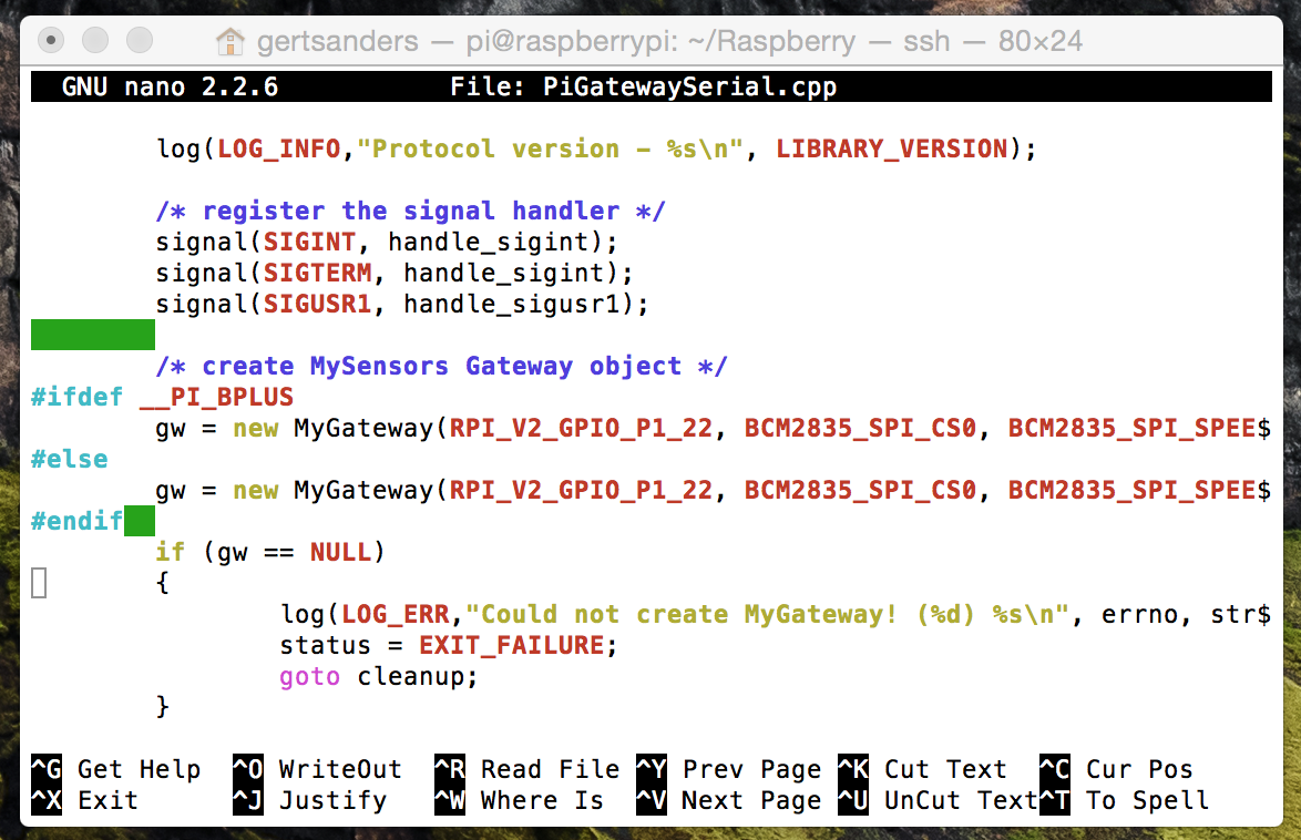
I'm not sure where the correction should be made so that the RPI2 is recognised properly (instead of being recognised a s a raspi B+)
-
All now working OK - many thanks!
-
I will need to document this. In the original post I followed to compile the gateway for rpi, this was also mentioned.
I would prefer that the code is corrected in the right place, because I feel the RPI2 should be recognised properly.
Anyway, happy to know there is a +1 user with a raspberry 2 and direct connected NRF24.
-
That's the code change I made (makes the 'if' redundant).
I've also changed the tty name (to /dev/ttyUSB40 - which is what I've declared to Domoticz) in this file and in Makefile.
BTW: Very impressed with OSH Park - got the PCBs here in UK (from US) 13 days after ordering!
-
This was the fourth board I ordered from OSHPark. For boards with ENIG finish, they are cheap. And the quality is indeed excellent. I have ordered a fifth design from them (should be ready end next week) and at the same time I sent my files to DirtyPCB. We will see what that gives quality wise. On this forum someone mentioned Shenzen2u and they are eaven cheaper then DirtyPCB. So my next design will also be ordered from those guys.
Now it's time to enjoy a local brew
-
@GertSanders Check out http://pcbshopper.com/, there are places slightly cheaper than DirtyPCB and places that will do runs of 5 boards instead of 10 for the same price per board. http://www.elecrow.com/ looks really good (5 boards for $15 delivered) but I haven't ordered from them yet so I can't comment on quality (other reviews of them say it's fine though).
-
I would rather pay 8.90 USD for 10 boards, then 15 USD for 5 boards delivered. http://www.shenzhen2u.com does the thing for me.
-
@GertSanders Did you have a shopping part list available? I've ordered your board at OSHPark and I've got the Caps in stock but not the blue thingy and the dupont blocks.
Could you put me in the right directorion where to shop those two parts?
-
Nevermind the dupont blocks. I've found those!
-
@Sander-Stolk The blue thingy is a ceramic 100nF capacitor, the two others are electrolytic capacitors of 100uF and 10uF respectively.
-
Thanks alot!
-
Anyone got a spare pcb i can purchase in the UK ?
Seems a waste ordering a batch.
An SD image would be good too??
-
What i select from drop down menu? Mysensors gateway USB ?
-
@Fat-Fly said:
What i select from drop down menu? Mysensors gateway USB ?
yes, follow these instructions:
-
Is there any pros/cons for using the nrf directly on the RPi instead of a NodeMCU?
Right now i use NodeMCU (esp) with nrf radio as gateway, but i want to reduce the nuber of units around my house so connecting directly to the RPi would be better as long as there is no negative sides to it.
-
For me there are no downsides. I use the raspberry as both gateway (with the NRF mounted) and as Domoticz controller. It is part of my home network and I can reach my Domoticz from the internet. So far I have 13 sensor nodes running and communicating with the raspberry.
-
@rmtucker I was thinking the same, don't need a whole batch. Anyone got a spare board, happy to pop some cash your way via a paypal gift.
-
I distributed my two other boards to friends locally. If you make the boards at OSH Park you get three boards (for a cost of 2.20 USD - shipping included).
-
I have the two spares from my order. If anyone wants one, send me a private chat message with your postal address. I am in the US, so it could take a few extra days to arrive if you are unfortunate enough to live on the wrong side of the pond.
-
@GertSanders Thanks for the heads up. I'd incorrectly assumed that it was going to be something like $10 plus shipping. At $2.20 it's nothing so ordered a few just for testing. Got carried away though and ordered a few 8266 breakout boards too

Col
-
I"m troubled. I know this will make me sound like a total newbie, but that's ok. From someone that is new to the form, it seems like you magically made the NRF work while it is physically attached to the RPi. I'm not finding any directions on how you made it work. I did find an old link that said that the directions on there will only work with 1.5X or below. Please show me the light.
-
Yes. I read too. NRF working directly with mysenosrs 1.5x. 2.0 not supported today.
-
Hi Gert,
Nice project! I am new to MySensors and Domoticz. Could you please briefly explain how to add the device to Domoticz. I have successfully done the steps from mfalkvidd's guide, but I am not sure how proceed in Domoticz. Any advise would be appreciated..
Best ,
IK<
-
If you sensors working ok than you need to go domoticz hardware-> devices. Marked with green arrow is new node. You need to press to green arrow and....... you see what you want.
Sorry my english. Maybe you understand.
-
Hi Fat Fly,
Thank you for your response. Unfortunately, I don't see a green arrow in hardware -> devices. My issue is that I don't understand how to add properly the Gateway. Should I add itas "MySensors Gateway USB"?

PS: your english are perfect
-
I would in Domoticz use MySensors Gateway USB and point to /dev/ttyMySensorsGateway
did you read the last part of the guide? where Mrfalkvidd specifically added a note for Domoticz , the below is taken from the link you are referring to:"Enable the gateway for use with Domoticz
Domoticz (and maybe other home automation systems) has trouble reading from the default path created by PiGatewaySerial. You might need to run the following command:sudo ln -s /dev/ttyMySensorsGateway /dev/ttyUSB20
And change /etc/rc.local from this
exit 0
to this:
ln -s /dev/ttyMySensorsGateway /dev/ttyUSB20
exit 0
"If this still isn't working for you, then make the standard serial gateway, with Arduino nano+NRF24L01+ (And capacitor on Vcc/GND as close to NRF module as possible) - this is for sure working

-
Thank you bjacobse!
It now works like a charm..
Best,
IK<
-
@Iraklis-Kourtis
Glad that you good it working and also replied that it's working for you