💬 Dimmable LED Actuator


  • Admin

    This thread contains comments for the article "Dimmable LED Actuator" posted on MySensors.org.


  • Hi,

    i am still kind of a beginner in programming...😞

    how does the:

     * This sketch is extensible to support more than one MOSFET/PWM dimmer per circuit.
     * http://www.mysensors.org/build/dimmer
    

    work?

    i have tried starting with adding a "_1" LED_PIN and other stuff:

    #define LED_PIN 3      // Arduino pin attached to MOSFET Gate pin
    #define LED_PIN_1 6      // Arduino pin attached to MOSFET Gate pin
    #define FADE_DELAY 35  // Delay in ms for each percentage fade up/down (10ms = 1s full-range dim)
    
    static int currentLevel = 0;  // Current dim level...
    static int currentLevel_1 = 0;  // Current dim level...
    MyMessage dimmerMsg(0, V_DIMMER);
    MyMessage dimmerMsg1(1, V_DIMMER);
    MyMessage lightMsg(0, V_LIGHT);
    MyMessage lightMsg1(1, V_LIGHT);
    
    /***
     * Dimmable LED initialization method
     */
    void setup()  
    { 
      // Pull the gateway's current dim level - restore light level upon sendor node power-up
      request( 0, V_DIMMER );
      request( 1, V_DIMMER );
    }
    
    void presentation() {
      // Register the LED Dimmable Light with the gateway
      present( 0, S_DIMMER );
      present( 1, S_DIMMER );
      
      sendSketchInfo(SN, SV);
    }
    

    , but this does not seem right, as i can not differentiat between for the input 😕

    thanks in advance


  • It looks like you are trying to add another LED/Mosfet? I have done it this way, I have 3 on mine:

    To do this I may or may not have used some examples I found on this forum. I basically add the pins I am using (PWM capable) into an array. I have 4 pins defined (3 is in there twice) to get around the array references starting from 0. Probably a better way to do that but this was my quick way round it.

    I have basically adapted the code from the example LED Dimmer sketch to work with the array / multiple child devices.

    Hopefully thats helpful and what you were after?

    // Enable debug prints to serial monitor
    #define MY_DEBUG 
    
    // Enable and select radio type attached
    #define MY_RADIO_NRF24
    //#define MY_RADIO_RFM69
    
    #include <SPI.h>
    #include <MySensors.h> 
    
    #define SN "MultiDimmableLED"
    #define SV "1.1"
    
    #define noLEDs 3
    const int LED_Pin[] = {3, 3, 5, 6}; //put 3 in twice as a start from 0 workaround
    
    #define FADE_DELAY 10  // Delay in ms for each percentage fade up/down (10ms = 1s full-range dim)
    
    static int currentLevel = 0;  // Current dim level...
    MyMessage dimmerMsg(noLEDs, V_DIMMER);
    MyMessage lightMsg(noLEDs, V_LIGHT);


    /***
     * Dimmable LED initialization method
     */
    void setup()  
    { 
      // not sure this works
      // Pull the gateway's current dim level - restore light level upon sendor node power-up
    for (int sensor=1; sensor<=noLEDs; sensor++){
      request( sensor, V_DIMMER );
     }
    }
    
    void presentation() {
      // Register the LED Dimmable Light with the gateway
     for (int sensor=1; sensor<=noLEDs; sensor++){
     present(sensor, S_DIMMER);
     delay(2);
     }
      sendSketchInfo(SN, SV);
    }
    
    /***
     *  Dimmable LED main processing loop 
     */
    void loop() 
    {
    }


    void receive(const MyMessage &message) {
      if (message.type == V_LIGHT || message.type == V_DIMMER) {
        
        //  Retrieve the power or dim level from the incoming request message
        int requestedLevel = atoi( message.data );
        
        // Adjust incoming level if this is a V_LIGHT variable update [0 == off, 1 == on]
        requestedLevel *= ( message.type == V_LIGHT ? 100 : 1 );
        
        // Clip incoming level to valid range of 0 to 100
        requestedLevel = requestedLevel > 100 ? 100 : requestedLevel;
        requestedLevel = requestedLevel < 0   ? 0   : requestedLevel;
        
        Serial.print( "Changing LED " );
        Serial.print(message.sensor);
        Serial.print(", PIN " );
        Serial.print( LED_Pin[message.sensor] );
        Serial.print(" level to " );
        Serial.print( requestedLevel );
        Serial.print( ", from " ); 
        Serial.println( currentLevel );
    
        
        fadeToLevel( requestedLevel, message.sensor );
        
        // Inform the gateway of the current DimmableLED's SwitchPower1 and LoadLevelStatus value...
        send(lightMsg.set(currentLevel > 0 ? 1 : 0));
    
        // hek comment: Is this really nessesary?
        send( dimmerMsg.set(currentLevel) );
    
        
        }
    }
    
    /***
     *  This method provides a graceful fade up/down effect
     */
    void fadeToLevel( int toLevel, int ledid ) {
    
      int delta = ( toLevel - currentLevel ) < 0 ? -1 : 1;
      
      while ( currentLevel != toLevel ) {
        currentLevel += delta;
        analogWrite( LED_Pin[ledid], (int)(currentLevel / 100. * 255) );
        delay( FADE_DELAY );
      }
    }


  • Contest Winner

    @thazlett144 can't help to make a few comments on your sketch (sorry)

    The led the array start from 0 and prevent the double pin declaration simply subtract one on usage so
    this LED_Pin[ledid] becomes this LED_Pin[ledid-1]

    please do use wait() instead of delay(), delay is blocking MySensors communication

        // hek comment: Is this really nessesary?
        send( dimmerMsg.set(currentLevel) );
    

    Answer: Yes, controllers like Vera want feedback about the new dimlevel


  • Hi,

    thank you both, i will be testing soon!

    thanks again!


  • so this works now like a charm:

    // Enable debug prints to serial monitor
    #define MY_DEBUG 
    
    // Enable and select radio type attached
    #define MY_RADIO_NRF24
    //#define MY_RADIO_RFM69
    
    #define MY_NODE_ID 153 
    
    #include <SPI.h>
    #include <MySensors.h> 
    
    #define SN "MultiDimmableLED"
    #define SV "1.1"
    
    #define noLEDs 3
    const int LED_Pin[] = {3, 5, 6}; 
    
    #define FADE_DELAY 25  // Delay in ms for each percentage fade up/down (10ms = 1s full-range dim)
    
    static int currentLevel = 0;  // Current dim level...
    MyMessage dimmerMsg(noLEDs, V_DIMMER);
    MyMessage lightMsg(noLEDs, V_LIGHT);


    /***
     * Dimmable LED initialization method
     */
    void setup()  
    { 
      // not sure this works
      // Pull the gateway's current dim level - restore light level upon sendor node power-up
    for (int sensor=1; sensor<=noLEDs; sensor++){
      request( sensor, V_DIMMER );
     }
    }
    
    void presentation() {
      // Register the LED Dimmable Light with the gateway
     for (int sensor=1; sensor<=noLEDs; sensor++){
     present(sensor, S_DIMMER);
     wait(2);
     }
      sendSketchInfo(SN, SV);
    }
    
    /***
     *  Dimmable LED main processing loop 
     */
    void loop() 
    {
    }


    void receive(const MyMessage &message) {
      if (message.type == V_LIGHT || message.type == V_DIMMER) {
        
        //  Retrieve the power or dim level from the incoming request message
        int requestedLevel = atoi( message.data );
        
        // Adjust incoming level if this is a V_LIGHT variable update [0 == off, 1 == on]
        requestedLevel *= ( message.type == V_LIGHT ? 100 : 1 );
        
        // Clip incoming level to valid range of 0 to 100
        requestedLevel = requestedLevel > 100 ? 100 : requestedLevel;
        requestedLevel = requestedLevel < 0   ? 0   : requestedLevel;
        
        Serial.print( "Changing LED " );
        Serial.print(message.sensor);
        Serial.print(", PIN " );
        Serial.print( LED_Pin[message.sensor] );
        Serial.print(" level to " );
        Serial.print( requestedLevel );
        Serial.print( ", from " ); 
        Serial.println( currentLevel );
    
        
        fadeToLevel( requestedLevel, message.sensor );
        
        // Inform the gateway of the current DimmableLED's SwitchPower1 and LoadLevelStatus value...
        send(lightMsg.set(currentLevel > 0 ? 1 : 0));
    
        // hek comment: Is this really nessesary?
        send( dimmerMsg.set(currentLevel) );
    
        
        }
    }
    
    /***
     *  This method provides a graceful fade up/down effect
     */
    void fadeToLevel( int toLevel, int ledid ) {
    
      int delta = ( toLevel - currentLevel ) < 0 ? -1 : 1;
      
      while ( currentLevel != toLevel ) {
        currentLevel += delta;
        analogWrite(LED_Pin[ledid-1], (int)(currentLevel / 100. * 255) );
        wait( FADE_DELAY );
      }
    }```
    
    thank you :thumbsup:

  • Hero Member

    I just tried the DimmableLightWithRotaryEncoderButton and I found that when rotating the rotary encoder clockwise the dim level decrease and turning it counter clockwise will increase the dim level. I would like it the other way around.

    Any ideas how to modify the sketch? Or is this a feature of my rotary encoder? Did I wire something wrong (I did check my wires and it is according to the instructions).


  • Admin

    Did you try just switching the pins for KNOB_ENC_PIN_x?


  • Hero Member

    @hek said:

    Did you try just switching the pins for KNOB_ENC_PIN_x?

    That did the trick. Thanks!


  • @BartE Thats great thank you. I am still learning anyway so there are gaps in my knowledge 🙂 I knew I could do something like that -1.

    delay was part of the original example I think?


  • Hi guys,

    Struggling with this a little and think it may be hardware related. I'm using a 3.3v pro mini and it won't let the 12v LEDs go to full brightness, at max dim level they're still quite dim. I've tried this on both regular flexi LED strip and the copper-wire type LEDs (final project is based on these).

    I've tried with a different FET, an IRLB8721 and that goes to full brightness however won't switch the LEDS off completely so guessing there's a leak from that FET! I'm not sure if that's normal or not. Frustrating.

    Ideally i want the circuitry to be 3.3v as i'm already converting the 12v LED power supply down to 3.3v for the nRF. I'd rather not have a 5v and 3.3v regulator.

    Thanks,

    Patrick


  • Mod

    @pjblink I had the same problem in https://forum.mysensors.org/topic/2335/controlling-leds-with-the-irlz44n/ and another community member had something similar: https://forum.mysensors.org/topic/2335/controlling-leds-with-the-irlz44n/

    The solution seems to be to buy new mosfets and hope that they work properly.


  • @mfalkvidd So keep trying IRLZ44N FETs?


  • Mod

    @pjblink probably. Several people have reported their IRLZ44N opening fully at 3.3V.


  • Hero Member

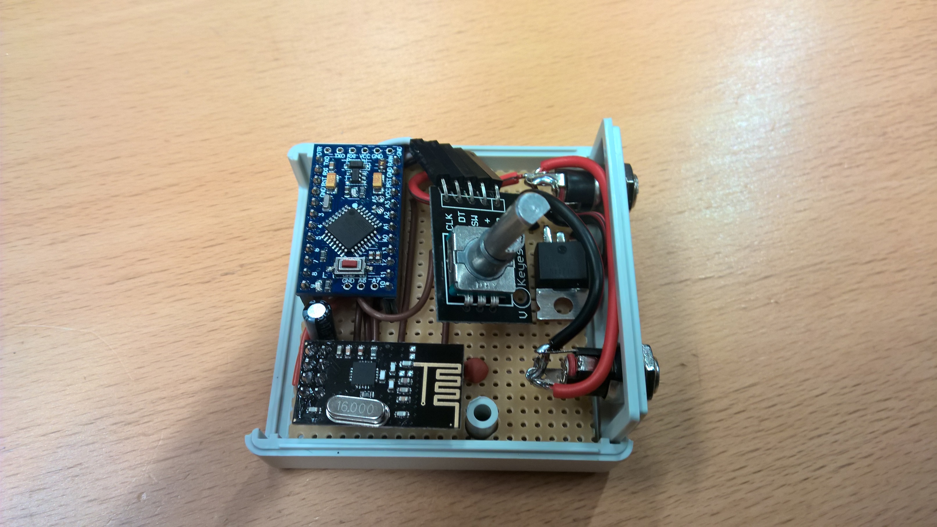
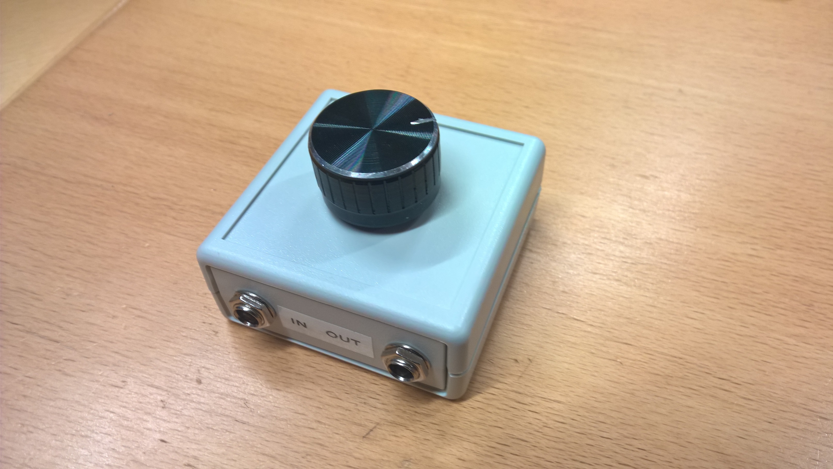
    Inspirational pictures from my Dimmable LED Actuator with rotary encoder device I made for my sons bedside lamp.
    Running this at 12VDC. His lamp had a G9 socket so I just broke apart the G9 LED bulb and soldered some G4 12VDC LED lights like these to it and replaces the "Dumb" switch with a 5mm DC plug. It turned out so nice that I think I will MySensor my own bedside lamp also.

    Edit: btw, I found the nice big knobs from here -> eBay

    0_1476680417320_WP_20161014_07_07_53.jpg

    0_1476680429390_WP_20161014_07_11_47.jpg


  • Hero Member

    Bahh.. I had the 12VDC connected directly to the RAW pin on the Arduino Pro mini and yesterday it failed.
    I should have known better. Now added a 5V regulator to the device and a new 5V Pro Mini.


  • Hi all
    I love the mysensors project. I have made a lot of sensors by now. Now I would like to control these LED-lights with a dimmer node:
    http://www.siriushome.dk/product/50200/ (in danish)
    The specs. for the LEDs are 6W@80V.
    I have two questions that I hope you can help me with.
    A) What is the easiest way to drive an arduinonode from 80v. Is a DC/DC converter the only way?
    B) What mosfet would you suggest using for controling the LEDs?

    I hope you can help. Many thanks.

    // MalmQ


  • @pjblink the irlzn44n is very sensitive to over heat during solder, I have lost some of them during soldering 🙂 please be careful


  • Hi!

    I'd like to use this sketch with a 5V Arduino Nano, do I need to use another type of MOSFET for this?
    From the OP I gather that the IRLZ44N is used because of the lower gate threshold in combination with the 3.3v operating voltage, but won't the IRLZ44N gate be saturated very quickly when using 5v?

    Creaky


  • Mod

    @Creaky the dimmer uses PWM to control the light level, so the mosfet is always either in cutoff or fully saturated. So using IRLz44N with 5V will work just as well as 3.3V.


  • @mfalkvidd Thanks for the reply!


  • @mfalkvidd Just so you know, there is no PWM involved in this sketch. I've just build this setup/node and it works great. You can see that the LED are continuously fed and brightness is changed by changing the voltage to the LEDs through the MOSFET.


  • Mod

    @Creaky the sketch linked in the first post uses pwm. But you might be using some other sketch?


  • It might be a very nice idea to use neopixels with this, a little expensive though when using a lot of LED's but still it's possible to dim them just by using code.. I am afraid I am not able to do that and it was just a small thought... 🙂


  • @mfalkvidd Yikes, you're right! I drew my conclusion too soon and only by watching the LED strip at max brightness. At max brightness the switching frequency is so high it is no longer perceptible by the eye. Mea culpa...


  • Mod

    @Creaky yes the switching is pretty quick. I guess that's the whole idea 🙂 I have noticed a refraction pattern in the kitchen sink when using a thin jet of water though.

    The analogWrite function in Arduino is very poorly named, since it doesn't really write an analog value. But I guess it is hard to change now.


  • I plan to use a LED strip as a closet light, controlled by a magnetic door switch, and of course also controllable in Domoticz. What would be the right way to write the code, should the pro mini send the state of the magnetic switch to the controller and then let the controller turn on the light, or is it easier to let the pro mini turn on the light directly and then report the state back to the controller? Big difference in delay?


  • It's a closet with two sliding doors and therefore two magnetic switches, and I want the LED to turn on when opening one of the doors, but also be able to turn it off remotely if we forgot to close it when leaving our home.


  • I would like to use this with a 48 Watt led which uses a constant-current power supply 54 - 87 VDC 600 ma output. This mosfet isn't high enough voltage rating, the IRF630MFP is rated at 200V 9amp, however I have questions about if the uC output will power the gate. The gate-source voltage is +/- 20. The VGS(th) gate threshold voltage is 2 to 4 volts with typ 3V. I would cut the negative from the power supply and connect to source, then connect the Led negative to drain, and connect the drain to ground on the uC? I need a reality check- does this sound possible or will I fry something?


  • Hi,
    I'm new in MySensors and build this Dimmer - LED with and without the rotary encoder which works fine.
    Now I would like to decouple the rotary encoder as a battery powered "standalone" sensor which is (in best case) connected directly to the LED-Dimmer. Furthermore the decoupled rotary encoder should be always in sleep mode until the rotary encoder awake the arduino.
    Is that possible ? I'm just stuck to seperate the code for the rotary encoder from the led-dimmer code.
    Thank you in advance.


  • hi, i used the example sketch. i also changed from "delay" to "wait" in fade section. The problem: i can change the percentage for example 8 times and then the gateway crashes and reboots. In a other case it works 12 times and then the gateway crashes. All other nodes (Temp, Hum) works fine all the time.


  • oh, i use mysensors serial gateway connected to a raspberry with fhem running.


  • Mod

    @joschre could you post the debug output from the node?


  • Problem solved! The 3.3v Form arduino nano was too Bad for the nrf24l01j pa lna with PA_LEVEL MAX. NOW i usw an external regulator an everything is fine 🙂 sorry for this newbie fault 😄


  • Mod

    @joschre great that you found a solution. Thank for reporting back.


  • Contest Winner

    Hi, I've noticed the V_DIMMER of the example is not (anymore?) available in https://www.mysensors.org/download/serial_api_20, am I wrong? Thanks


  • Mod

    @user2684 you're right. I think it is supposed to be S_DIMMER (S_ is used for presentation)


  • Dear Guys,

    How can I control an RGB ledstrip with this config may I add more MOSFAT or how ?
    Thank you very much.

    L


  • Hero Member

    @Laces yes you can. The principal is the same, just one mosfet per channel.
    Search the forum for RGB or RGBW and you sould be able to find some examples.


  • This post is deleted!


  • This post is deleted!


  • Ah I have just built a test bed with this setup however it appears the circuit diagram in the Fritizing is actually not 100% correct. The red wire from the protoboard is connected to the GND of the Pro Mini - this confused me as I was using the GND/RAW pins to identify the cable color. If you flip the red/blue connections on the Pro Mini it will be right. Small issue I know but I had to reference another image to get the circuit to work.


  • Hi Folks,

    I have build this in combination with a ethernet gateway. Works perfect, however, when for whatever reason the network fails, I cannot control my lights anymore.

    Is there a possibilty toi have it working also "stand alone" when the network fails?

    Grtz.

    KoenP


  • Hi all!

    I'm using OpenHAB 2, and I have some problems with the sketch code "DimmableLightWithRotaryEncoderButton".

    1. When the encoder button is pressed, the switch in OpenHAB does not respond.
    2. When you turn the encoder knob one step, the value changes in two steps.

    Maybe you have encountered such a problem? Or maybe you can share a more modern sketch?


  • Mod

    In case anyone can help @vladimir, please post in https://forum.mysensors.org/post/93111 so we keep the discussion focused in one place.


  • Does anyone use this sketch "DimmableLightWithRotaryEncoderButton"? I take it from the site (https://www.mysensors.org/build/dimmer) and it does not work with OpenHAB 2.


  • does anyone have working sketch -> DimmableLightWithRotaryEncoderButton.ino with Mysensor USB under DOMOTICZ + Arduino ? unfortunatelly phisical button dosn't work (no switch on / off) and there is no feedbeck from domoticz to Arduino to set level of dim. I have been straggling with the sketch for weeks, but haven't figured out , how to fix it. Mybe something has changed since lat update od sketch... and sorry for my english I'm not a native speaker:)


  • @hard-shovel I've already used this sketch, but still no feedback from domoticz to arduino (it does not dim) and the physical button doesn't work 😞 ehh...


  • here is what I use now->
    As I can see When I change the dim level or click the switch in domoticz the yellow led on arduino blink but it changes nothing..

    
    /**
     * The MySensors Arduino library handles the wireless radio link and protocol
     * between your home built sensors/actuators and HA controller of choice.
     * The sensors forms a self healing radio network with optional repeaters. Each
     * repeater and gateway builds a routing tables in EEPROM which keeps track of the
     * network topology allowing messages to be routed to nodes.
     *
     * Created by Henrik Ekblad <henrik.ekblad@mysensors.org>
     * Copyright (C) 2013-2015 Sensnology AB
     * Full contributor list: https://github.com/mysensors/Arduino/graphs/contributors
     *
     * Documentation: http://www.mysensors.org
     * Support Forum: http://forum.mysensors.org
     *
     * This program is free software; you can redistribute it and/or
     * modify it under the terms of the GNU General Public License
     * version 2 as published by the Free Software Foundation.
     *
     *******************************
     *
     * REVISION HISTORY
     * Version 1.0 - Developed by Bruce Lacey and GizMoCuz (Domoticz)
     * Version 1.1 - Modified by hek to incorporate a rotary encode to adjust 
     *                                light level locally at node
     * 
     * DESCRIPTION
     * This sketch provides an example how to implement a dimmable led light node with a rotary 
     * encoder connected for adjusting light level. 
     * The encoder has a click button which turns on/off the light (and remembers last dim-level) 
     * The sketch fades the light (non-blocking) to the desired level. 
     *
     * Default MOSFET pin is 3
     * 
     *  Arduino      Encoder module
     *  ---------------------------
     *  5V           5V (+)  
     *  GND          GND (-)
     *  4            CLK (or putput 1) 
     *  5            DT  (or output 1) 
     *  6            SW (Switch/Click) 
     */
    // Enable and select radio type attached
    //#define MY_RADIO_NRF24
    //#define MY_RADIO_RFM69
    
    // Enable debug prints
    #define MY_DEBUG
    #define MY_GATEWAY_SERIAL
    #define MY_INCLUSION_MODE_FEATURE
    #define MY_INCLUSION_BUTTON_FEATURE
    #define MY_INCLUSION_MODE_DURATION 60
    #define MY_INCLUSION_MODE_BUTTON_PIN 8
    
    #include <SPI.h>
    #include <MySensors.h>  
    #include <Bounce2.h>
    #include <Encoder.h>
    
    #define LED_PIN 3           // Arduino pin attached to MOSFET Gate pin
    #define KNOB_ENC_PIN_1 4    // Rotary encoder input pin 1
    #define KNOB_ENC_PIN_2 5    // Rotary encoder input pin 2
    #define KNOB_BUTTON_PIN 6   // Rotary encoder button pin 
    #define FADE_DELAY 10       // Delay in ms for each percentage fade up/down (10ms = 1s full-range dim)
    #define SEND_THROTTLE_DELAY 400 // Number of milliseconds before sending after user stops turning knob
    #define SN "DimmableLED /w button"
    #define SV "1.3"
    
    #define CHILD_ID_LIGHT 1
    
    #define EEPROM_DIM_LEVEL_LAST 1
    #define EEPROM_DIM_LEVEL_SAVE 2
    
    #define LIGHT_OFF 0
    #define LIGHT_ON 1
    
    int dimValue;
    int fadeTo;
    int fadeDelta;
    byte oldButtonVal;
    bool changedByKnob=false;
    bool sendDimValue=false;
    unsigned long lastFadeStep;
    unsigned long sendDimTimeout;
    char convBuffer[10];
    
    MyMessage dimmerMsg(CHILD_ID_LIGHT, V_DIMMER);
    MyMessage statusMsg(CHILD_ID_LIGHT, V_STATUS);    // Addition for Status update to OpenHAB Controller
    Encoder knob(KNOB_ENC_PIN_1, KNOB_ENC_PIN_2);  
    Bounce debouncer = Bounce(); 
    
    void setup()  
    { 
      // Set knob button pin as input (with debounce)
      pinMode(KNOB_BUTTON_PIN, INPUT);
      digitalWrite(KNOB_BUTTON_PIN, HIGH);
      debouncer.attach(KNOB_BUTTON_PIN);
      debouncer.interval(5);
      oldButtonVal = debouncer.read();
    
      // Set analog led pin to off
      analogWrite( LED_PIN, 0);
    
      // Retreive our last dim levels from the eprom
      fadeTo = dimValue = 0;
      byte oldLevel = loadLevelState(EEPROM_DIM_LEVEL_LAST);
      Serial.print("Sending in last known light level to controller: ");
      Serial.println(oldLevel);  
      send(dimmerMsg.set(oldLevel), true);
      Serial.println("Ready to receive messages...");  
    }
    
    void presentation() {
      // Send the Sketch Version Information to the Gateway
      present(CHILD_ID_LIGHT, S_DIMMER);
      sendSketchInfo(SN, SV);
    }
    
    void loop()      
    {
      // Check if someone turned the rotary encode
      checkRotaryEncoder();
      
      // Check if someone has pressed the knob button
      checkButtonClick();
      
      // Fade light to new dim value
      fadeStep();
    }
    
    void receive(const MyMessage &message)
    {
      if (message.type == V_STATUS) {
        // Incoming on/off command sent from controller ("1" or "0")
        int lightState = message.getString()[0] == '1';
        int newLevel = 0;
        if (lightState==LIGHT_ON) {
          // Pick up last saved dimmer level from the eeprom
          newLevel = loadLevelState(EEPROM_DIM_LEVEL_SAVE);
        } 
        // Send dimmer level back to controller with ack enabled
        send(dimmerMsg.set(newLevel), true);
        // We do not change any levels here until ack comes back from gateway 
        return;
      } else if (message.type == V_PERCENTAGE) {
        // Incoming dim-level command sent from controller (or ack message)
        fadeTo = atoi(message.getString(convBuffer));
        // Save received dim value to eeprom (unless turned off). Will be
        // retreived when a on command comes in
        if (fadeTo != 0)
          saveLevelState(EEPROM_DIM_LEVEL_SAVE, fadeTo);
      }
      saveLevelState(EEPROM_DIM_LEVEL_LAST, fadeTo);
      
      Serial.print("New light level received: ");
      Serial.println(fadeTo);
    
      if (!changedByKnob) 
        knob.write(fadeTo<<1);             //### need to multiply by two (using Shift left)
        
      // Cancel send if user turns knob while message comes in
      changedByKnob = false;
      sendDimValue = false;
    
      // Stard fading to new light level
      startFade();
    }


    void checkRotaryEncoder() {
      long encoderValue = knob.read()>>1 ;      //### Divide by 2 (using shift right) 
    
      if (encoderValue > 100) {   
        encoderValue = 100;       
        knob.write(200);                        //### max value now 200 due to divide by 2
      } else if (encoderValue < 0) {
        encoderValue = 0;
        knob.write(0);
      }
    
      if (encoderValue != fadeTo) {    
        fadeTo = encoderValue;                   
        changedByKnob = true;
        startFade();
      }
    }
    
    void checkButtonClick() {
      debouncer.update();
      byte buttonVal = debouncer.read();
      byte newLevel = 0;
      if (buttonVal != oldButtonVal && buttonVal == LOW) {
        if (dimValue==0) {
          // Turn on light. Set the level to last saved dim value
          int saved = loadLevelState(EEPROM_DIM_LEVEL_SAVE);
          newLevel = saved > 1 ? saved : 100;           // newLevel = saved > 0 ? saved : 100;     
        } 
        send(dimmerMsg.set(newLevel),true);
        send(statusMsg.set(newLevel>0 ? "1" : "0")); // Addition for Status update to OpenHAB Controller,   No Echo
      }
      oldButtonVal = buttonVal;
    }
    
    void startFade() {
      fadeDelta = ( fadeTo - dimValue ) < 0 ? -1 : 1;
      lastFadeStep = millis();
    }
    
    // This method provides a graceful none-blocking fade up/down effect
    void fadeStep() {
      unsigned long currentTime  = millis();
      if ( dimValue != fadeTo && currentTime > lastFadeStep + FADE_DELAY) {
        dimValue += fadeDelta;
        analogWrite( LED_PIN, (int)(dimValue / 100. * 255) );
        lastFadeStep = currentTime;
        
        Serial.print("Fading level: ");
        Serial.println(dimValue);
    
        if (fadeTo == dimValue && changedByKnob) {
          sendDimValue = true;
          sendDimTimeout = currentTime;
        }
      } 
      // Wait a few millisecs before sending in new value (if user still turns the knob)
      if (sendDimValue && currentTime > sendDimTimeout + SEND_THROTTLE_DELAY)  {
         // We're done fading.. send in new dim-value to controller.
         // Send in new dim value with ack (will be picked up in incomingMessage) 
        send(dimmerMsg.set(dimValue), true); // Send new dimmer value and request ack back
        sendDimValue = false;
      }
    }
    
    // Make sure only to store/fetch values in the range 0-100 from eeprom
    int loadLevelState(byte pos) {
      return min(max(loadState(pos),0),100);
    }
    void saveLevelState(byte pos, byte data) {
      saveState(pos,min(max(data,0),100));
    }


  • @mateos78
    Attached is a sketch that i have just tried with domoticz (running on a windows test machine) It works fine when used as a node with a gateway. Encoder/ Switch and webpage slider/switch operating.

    However when set up as a single gateway node as your sketch, only the encoder function works, you can vary the lamp level from the slider or the encoder, but the domaticz on/off or the button does not operate correctly. it seems to be the way the messages are acknowledged

    I also find that when i change the led dimmer from the encoder the led changes quickly, but it take about ten seconds before the dormoticz web page updates to show each new slider position.

    The following Sketch needs the #define OPENHAB2 defined for use with openhab and undefined for Dormoticz

    /**
     * The MySensors Arduino library handles the wireless radio link and protocol
     * between your home built sensors/actuators and HA controller of choice.
     * The sensors forms a self healing radio network with optional repeaters. Each
     * repeater and gateway builds a routing tables in EEPROM which keeps track of the
     * network topology allowing messages to be routed to nodes.
     *
     * Created by Henrik Ekblad <henrik.ekblad@mysensors.org>
     * Copyright (C) 2013-2015 Sensnology AB
     * Full contributor list: https://github.com/mysensors/Arduino/graphs/contributors
     *
     * Documentation: http://www.mysensors.org
     * Support Forum: http://forum.mysensors.org
     *
     * This program is free software; you can redistribute it and/or
     * modify it under the terms of the GNU General Public License
     * version 2 as published by the Free Software Foundation.
     *
     *******************************
     * DESCRIPTION
     * This sketch provides an example how to implement a dimmable led light node with a rotary 
     * encoder connected for adjusting light level. 
     * The encoder has a click button which turns on/off the light (and remembers last dim-level) 
     * The sketch fades the light (non-blocking) to the desired level. 
     *
     * Default MOSFET pin is 3
     * 
     *  Arduino      Encoder module
     *  ---------------------------
     *  5V           5V (+)  
     *  GND          GND (-)
     *  4            CLK (or putput 1)
     *  5            DT  (or output 1) 
     *  6            SW (Switch/Click)  
     *
     *  For OpenHAB2  enable @define OPENHAB2
     *  
     *  NOTE
     *  PROBLEM: 
     *  Using as a Gateway Node With Dormoticz the SWITCH ON/OFF DOES not work correcly either from the controller or by the Encoder 
     *  Using as a normal node all functions operate correctly.
     *  
      */
     /
    
     
    // Enable debug prints
    //#define MY_DEBUG


    // --- Enable Serial Gateway Transport
    #define MY_GATEWAY_SERIAL
    //#define MY_INCLUSION_MODE_FEATURE
    //#define MY_INCLUSION_BUTTON_FEATURE
    //#define MY_INCLUSION_MODE_DURATION 60
    //#define MY_INCLUSION_MODE_BUTTON_PIN 8
    
    
    // --- Enable RS485 transport layer
    //#define MY_RS485
    // Define this to enables DE-pin management on defined pin
    //#define MY_RS485_DE_PIN 12
    // Set RS485 baud rate to use
    //#define MY_RS485_BAUD_RATE 9600


    // Enable and select radio type attached
    //#define MY_RADIO_NRF24
    //#define MY_RADIO_RFM69
    
    #include <SPI.h>
    #include <MySensors.h>  
    #include <Bounce2.h>
    #include <Encoder.h>
    
    #define LED_PIN 3           // Arduino pin attached to MOSFET Gate pin
    #define KNOB_ENC_PIN_1 4    // Rotary encoder input pin 1
    #define KNOB_ENC_PIN_2 5    // Rotary encoder input pin 2
    #define KNOB_BUTTON_PIN 6   // Rotary encoder button pin 
    #define FADE_DELAY 10       // Delay in ms for each percentage fade up/down (10ms = 1s full-range dim)
    #define SEND_THROTTLE_DELAY 400 // Number of milliseconds before sending after user stops turning knob
    #define SN "DimmableLED /w button"
    #define SV "1.3a"
    
    #define CHILD_ID_LIGHT 1
    
    #define EEPROM_DIM_LEVEL_LAST 1
    #define EEPROM_DIM_LEVEL_SAVE 2
    // #define OPENHAB2                      // Use Define if using OPENHAB2 
    
    #define LIGHT_OFF 0
    #define LIGHT_ON 1
    
    int dimValue;
    int fadeTo;
    int fadeDelta;
    byte oldButtonVal;
    bool changedByKnob=false;
    bool sendDimValue=false;
    unsigned long lastFadeStep;
    unsigned long sendDimTimeout;
    char convBuffer[10];
    
    MyMessage dimmerMsg(CHILD_ID_LIGHT, V_DIMMER);
    MyMessage statusMsg(CHILD_ID_LIGHT, V_STATUS);    // Addition for Status update to OpenHAB Controller
    Encoder knob(KNOB_ENC_PIN_1, KNOB_ENC_PIN_2);  
    Bounce debouncer = Bounce(); 
    
    void setup()  
    { 
      // Set knob button pin as input (with debounce)
      pinMode(KNOB_BUTTON_PIN, INPUT);
      digitalWrite(KNOB_BUTTON_PIN, HIGH);
      debouncer.attach(KNOB_BUTTON_PIN);
      debouncer.interval(5);
      oldButtonVal = debouncer.read();
    
      // Set analog led pin to off
      analogWrite( LED_PIN, 0);
    
      // Retreive our last dim levels from the eprom
      fadeTo = dimValue = 0;
      byte oldLevel = loadLevelState(EEPROM_DIM_LEVEL_LAST);
      Serial.print("Sending in last known light level to controller: ");
      Serial.println(oldLevel);  
      send(dimmerMsg.set(oldLevel), true);
      Serial.println("Ready to receive messages...");  
    }
    
    void presentation() {
      // Send the Sketch Version Information to the Gateway
      present(CHILD_ID_LIGHT, S_DIMMER);
      sendSketchInfo(SN, SV);
    }
    
    void loop()      
    {
      // Check if someone turned the rotary encode
      checkRotaryEncoder();
      
      // Check if someone has pressed the knob button
      checkButtonClick();
      
      // Fade light to new dim value
      fadeStep();
    }
    
    void receive(const MyMessage &message)
    {
        #ifdef MY_DEBUG
        // This is called when a message is received 
        Serial.print("Message: "); Serial.print(message.sensor); Serial.print(", type: "); Serial.print(message.type); Serial.print(", Message: ");
        #endif
        
      if (message.type == V_STATUS) {
        // Incoming on/off command sent from controller ("1" or "0")
        int lightState = message.getString()[0] == '1';
        int newLevel = 0;
        if (lightState==LIGHT_ON) {
          // Pick up last saved dimmer level from the eeprom
          newLevel = loadLevelState(EEPROM_DIM_LEVEL_SAVE);
        } else {
          
        }
        // Send dimmer level back to controller with ack enabled
        send(dimmerMsg.set(newLevel), true);
        // We do not change any levels here until ack comes back from gateway 
        return;
      } else if (message.type == V_PERCENTAGE) {
        // Incoming dim-level command sent from controller (or ack message)
        fadeTo = atoi(message.getString(convBuffer));
        // Save received dim value to eeprom (unless turned off). Will be
        // retreived when a on command comes in
        if (fadeTo != 0)
          saveLevelState(EEPROM_DIM_LEVEL_SAVE, fadeTo);
      }
      saveLevelState(EEPROM_DIM_LEVEL_LAST, fadeTo);
      #ifdef MY_DEBUG
      Serial.print("New light level received: ");
      Serial.println(fadeTo);
      #endif
      
      if (!changedByKnob) 
        knob.write(fadeTo<<1);             //### need to multiply by two (using Shift left)
        
      // Cancel send if user turns knob while message comes in
      changedByKnob = false;
      sendDimValue = false;
    
      // Stard fading to new light level
      startFade();
    }


    void checkRotaryEncoder() {
      long encoderValue = knob.read()>>1 ;      //### Divide by 2 (using shift right) 
    
      if (encoderValue > 100) {   
        encoderValue = 100;       
        knob.write(200);                        //### max value now 200 due to divide by 2
      } else if (encoderValue < 0) {
        encoderValue = 0;
        knob.write(0);
      }
    
      if (encoderValue != fadeTo) {    
        fadeTo = encoderValue;                   
        changedByKnob = true;
        startFade();
      }
    }
    
    void checkButtonClick() {
      debouncer.update();
      byte buttonVal = debouncer.read();
      byte newLevel = 0;
      if (buttonVal != oldButtonVal && buttonVal == LOW) {
        if (dimValue==0) {
          // Turn on light. Set the level to last saved dim value
          int saved = loadLevelState(EEPROM_DIM_LEVEL_SAVE);
          newLevel = saved > 1 ? saved : 100;           // newLevel = saved > 0 ? saved : 100;     
        } 
        send(dimmerMsg.set(newLevel),true);
        #ifdef OPENHAB2
        send(statusMsg.set(newLevel>0 ? "1" : "0")); // Addition for Status update to OpenHAB Controller,   No Echo
        #endif
      }
      oldButtonVal = buttonVal;
    }
    
    void startFade() {
      fadeDelta = ( fadeTo - dimValue ) < 0 ? -1 : 1;
      lastFadeStep = millis();
    }
    
    // This method provides a graceful none-blocking fade up/down effect
    void fadeStep() {
      unsigned long currentTime  = millis();
    
      if ( dimValue != fadeTo && currentTime > lastFadeStep + FADE_DELAY) {
        dimValue += fadeDelta;
        analogWrite( LED_PIN, (int)(dimValue / 100. * 255) );
        lastFadeStep = currentTime;
        #ifdef MY_DEBUG
        Serial.print("Fading level: ");
        Serial.println(dimValue);
        #endif
        
        if (fadeTo == dimValue && changedByKnob) {
          sendDimValue = true;
          sendDimTimeout = currentTime;
        }
      } 
      // Wait a few millisecs before sending in new value (if user still turns the knob)
      if (sendDimValue && currentTime > sendDimTimeout + SEND_THROTTLE_DELAY)  {
         // We're done fading.. send in new dim-value to controller.
         // Send in new dim value with ack (will be picked up in incomingMessage) 
        send(dimmerMsg.set(dimValue), true); // Send new dimmer value and request ack back
        sendDimValue = false;
      }
    }
    
    // Make sure only to store/fetch values in the range 0-100 from eeprom
    int loadLevelState(byte pos) {
      return min(max(loadState(pos),0),100);
    }
    void saveLevelState(byte pos, byte data) {
      saveState(pos,min(max(data,0),100));
    }
    

    I maybe overlooking something obvious as i only have a couple of hours experience with domoticz.


  • @hard-shovel thanks a lot for you post and effort to test it!, I've tested also the version of sketch without rotary encoder and this one works fine.


  • So, does anybody use "Example with Rotary Encoder" with DOMOTICZ? I'm trying to force the sketch to work, but for time being without any result:(


  • Hello,
    could someone possibly add a relay to the sketch? Have with all my dimmer problems so that they often dont turn off the LEDs. Maybe it's up to my controller software. And my programming skill are not really good.

    Thx Sarg666


  • Hello,

    when compiling the standard example https://github.com/mysensors/MySensors/blob/master/examples/DimmableLEDActuator/DimmableLEDActuator.ino

    on the IDE 1.8.12 :

    Return this error :

    C:\Users\James\Documents\Arduino\sketch_may16a-test\sketch_may16a-test.ino: In function 'void receive(const MyMessage&)':
    
    sketch_may16a-test:88:15: error: 'const class MyMessage' has no member named 'getType'; did you mean 'setType'?
    
       if (message.getType() == V_LIGHT || message.getType() == V_DIMMER) {
    
                   ^~~~~~~
    
                   setType
    
    sketch_may16a-test:88:47: error: 'const class MyMessage' has no member named 'getType'; did you mean 'setType'?
    
       if (message.getType() == V_LIGHT || message.getType() == V_DIMMER) {
    
                                                   ^~~~~~~
    
                                                   setType
    
    sketch_may16a-test:94:33: error: 'const class MyMessage' has no member named 'getType'; did you mean 'setType'?
    
         requestedLevel *= ( message.getType() == V_LIGHT ? 100 : 1 );
    
                                     ^~~~~~~
    
                                     setType
    
    exit status 1
    'const class MyMessage' has no member named 'getType'; did you mean 'setType'?
    

    Can someone help?

    All the best!


  • @ZwaZo

    The example compiles for me in IDE 1.8.12

    Sketch uses 14338 bytes (46%) of program storage space. Maximum is 30720 bytes.
    Global variables use 503 bytes (24%) of dynamic memory, leaving 1545 bytes for local variables. Maximum is 2048 bytes.
    

    Please verify that you are using the latest version of the MySensors library (2.3.2).


  • @ZwaZo said in 💬 Dimmable LED Actuator:

    meon

    Nope, I'm still on 2.2.2


  • @BearWithBeard I have upgraded the library V.2.3.2 and it compiles now. 🙂

    Thanks for your help!


  • Does this need a resistor between the Arduino digital pin and the Gate of the MOSFET? To limit current draw?


Log in to reply
 

Suggested Topics

  • 3
  • 2
  • 584
  • 347
  • 109
  • 163

0
Online

11.2k
Users

11.1k
Topics

112.5k
Posts