Navigation

    • Register
    • Login
    • OpenHardware.io
    • Categories
    • Recent
    • Tags
    • Popular
    1. Home
    2. Koresh
    3. Best
    • Profile
    • Following
    • Followers
    • Topics
    • Posts
    • Best
    • Groups

    Best posts made by Koresh

    • MySensors 2.3 and RFM69 new driver. Problems and solutions

      Hi everyone. I want to share the results of a small investigation into MySensors 2.3 and rfm69 new driver environment. I decided to do it after I bumped into some problems.
      I hope it will be interesting for everyone. Newbies can find simple recommendations to improve MySensors stability. Experienced users end core team members can implement my ideas into the mainline version in the right way.
      Let me remind you of the problem briefly. If you try to run this code to send two messages from the node to gateway only the first message will be sent properly.

      send(message1, true);
      send(message2, true);
      

      Chapter 1. Second ACK
      Let’s see how mysensors with rfm69 processes incoming messages. Just when rfm69 receives the message, it generates interrupt which is handled by rfm69 driver. But… in this interrupt the driver does not process the message. It only sets RFM69_irq flag.

      // IRQ handler: PayloadReady (RX) & PacketSent (TX) mapped to DI0
      LOCAL void RFM69_interruptHandler(void)
      {
      	// set flag
      	RFM69_irq = true;
      }
      

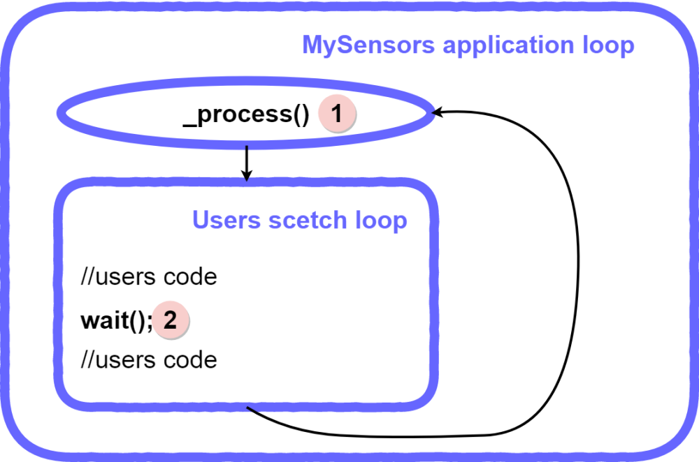
      Later process() function reads this flag and reads messages from rfm69. So the first important point. Incoming messages can be processed only in two places of application code:

      1. Inside the process() function at the beginning of the main mysensors application loop.
      2. Inside the wait() function anywhere you call it (it actually calls the process() function too).

      0_1531061212559_MysLoopDiagram.png
      There is only one exception to this rule. Just when you send any message with ACK request, the rfm69 driver is waiting for the ACK message. So at this moment your application can get a message too. If it is an expected ack it will be processed, otherwise – just received and not processed.

      Now we know a little more about how mysensors processes incoming messages and I will try to describe how a very simple usecase works. Let’s imagine that the node sends one message to the gateway

      send(message1, true);
      

      In the following diagram I tried to explain in detail the behavior of the application from both sides – gateway and the node.

      0_1531061319581_OneMessageDiagram.png

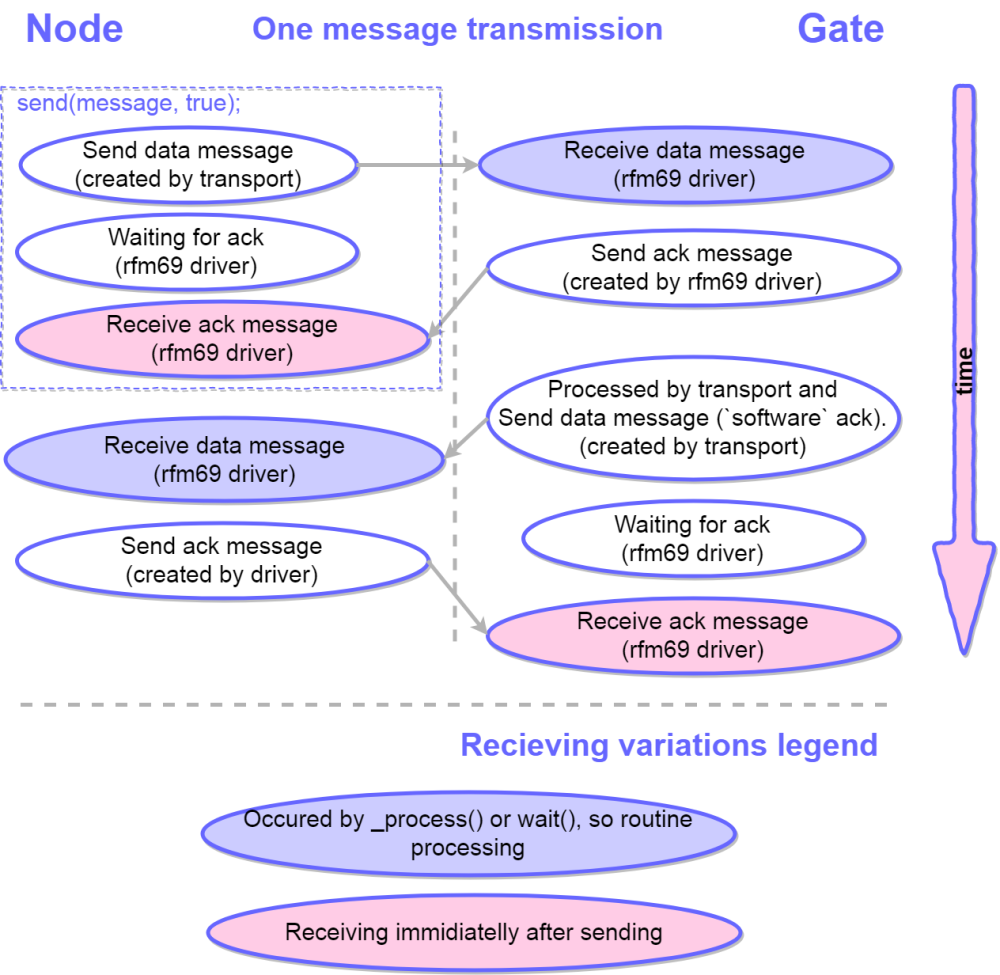
      As you can see this case works properly.
      Now we can imagine a more complex case. The node sends two messages to the gateway one by one.

      send(message1, true);
      send(message2, true);
      

      Yes this is the same code which I wrote at the start of this topic. So the next diagram describes how it works.

      0_1531061380920_TwoMessagesDiagram.png

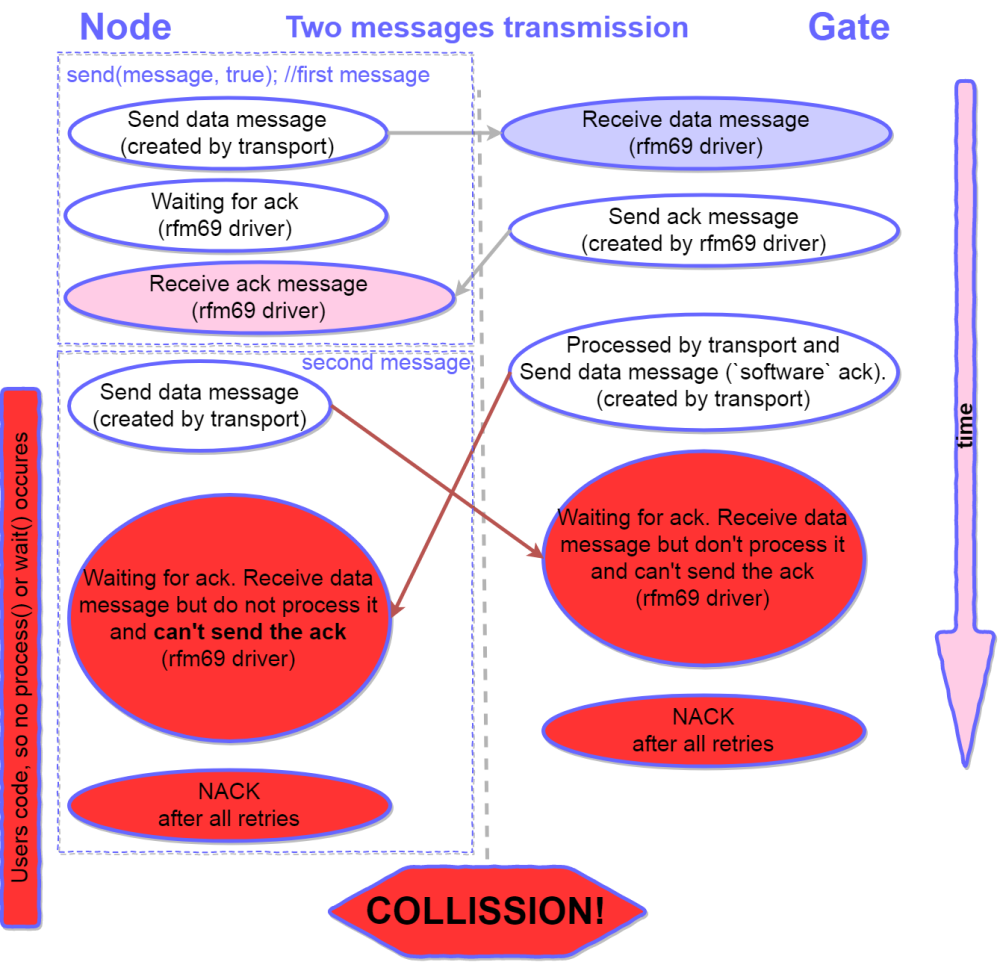
      Oops… The second ACK will break the communication in this case? Yes – 99% it causes the problems. But why is this second ACK needed at all? I am not entirely sure, but I will try to explain my understanding of this second ack (how it should work).

      0_1531061521771_SoftwareAck.png

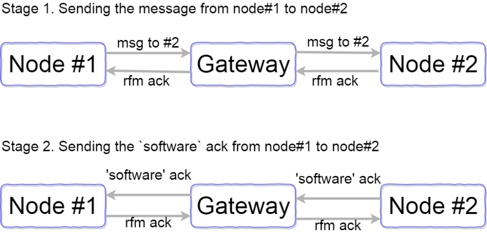
      So this second ACK theoretically can help you know if your message was delivered to the node which is behind the gate. But in real life it brakes the communication.

      How can we fix it? How can we send two messages one by one without collision? I will describe some solutions.
      First solution is very simple but very bad and I strongly recommend against implementing it. Just add wait(100) between the lines

      send(message1, true);
      wait(100);
      send(message2, true);
      

      Why is this solution bad? First it causes a dramatic rise in battery consumption. There are two messages in this case. If you want to send 4-5 messages our sketch will work 400ms longer! Second it is absolutely wrong from the application design point. We are trying to fix the transport layer error on the user application layer. So implement this solution as last resort.

      Second solution is not a very good one but I would recommend it for anyone who uses simple mysensors setups with relatively simple sketches without any complicated customization. Just disable the second ACK!

      //MyTransport.cpp line723
      // send ACK, use transportSendRoute since ACK reply is not internal, i.e. if !transportOK do not reply
      #ifndef MY_RADIO_RFM69
        (void)transportSendRoute(_msgTmp);
      #endif
      

      or just comment it 🙂

      // send ACK, use transportSendRoute since ACK reply is not internal, i.e. if !transportOK do not reply
      //(void)transportSendRoute(_msgTmp);
      

      This simple hack will increase your network speed and reliability sharply. For example this code

      for (int m = 1; m < 200; m ++){
           send(msg_sw.set(m), true);
        }
      

      will send 200 messages with ACK requests one by one and not a single NACK has ever appeared. I tried it many times.
      What do you lose if you implement this solution? You will not see this message

      45899 TSF:MSG:READ,0-0-144,s=1,c=1,t=2,pt=1,l=1,sg=0:0
      45905 TSF:MSG:ACK
      

      in the debug serial output of the node. I think 95% of users do not process such messages in the sketch and it is not a big loss.
      If you want to process these ACK messages to check the delivery to the node which is behind the gate you can implement the third more clever solution

      // send ACK, use transportSendRoute since ACK reply is not internal, i.e. if !transportOK do not reply
      #ifndef MY_RADIO_RFM69
      #ifndef MY_GATEWAY_FEATURE
        (void)transportSendRoute(_msgTmp);
      #endif
      #endif
      

      Or

      // send ACK, use transportSendRoute since ACK reply is not internal, i.e. if !transportOK do not reply
      #ifndef MY_RADIO_RFM69
      if (_msg.last != _msg.sender){
        (void)transportSendRoute(_msgTmp);
      }
      #endif
      

      It makes your network more stable too. In the first example we disable software ACK (second ACK) from the gateway to the node. In the second example we disable software ACK from one node to another node if there are no nodes between them (I haven’t tested this case but It can work).

      But imagine you do not want to implement this hack at all. How can we fix this problem differently? Let’s move to the next chapter.

      Chapter 2. The queue of the messages.
      The messages queue is standard in different systems. It is nonsense to omit this feature in a serious system. Moreover, MySensors team implements this feature… but for NRF24 not for RFM69.
      I will not describe in detail how message queue works. You only should know that received messages are read immediately after they are received (inside the interrupt handler) and put into the queue. They can be processed later but we do not omit a single one.
      I will try to implement queue message for the RFM69 transport and drivers level. I have a very good example for NRF24 so it was not very hard. I bumped only into one serious problem (yet:)). NRF24 driver uses autoACK function, which is not supported by rfm69. If we want to send ACK inside the interrupt handler we can’t use time system functions (millis(), delay() and so on). So I implement Ack sending function without forbidden functions.
      You can see my draft solution on the easysensors github (will share soon, may be today). Most of the changes are in the MyTransportRF24.cpp and RFM69_new.cpp. If you want to try it you should also remove mysensors capabilities protection like this in some places

      #if defined(MY_RADIO_RFM69)
      #error Receive message buffering not supported for RFM69!
      #endif
      

      I haven’t tested it thoroughly. But I have tested it to check if «DOUBLE ACK» problem is solved. And yes – it is solved. The next diagram shows how this code works with my new transport and driver

      0_1531062561670_TwoMessagesDiagram_queue.png

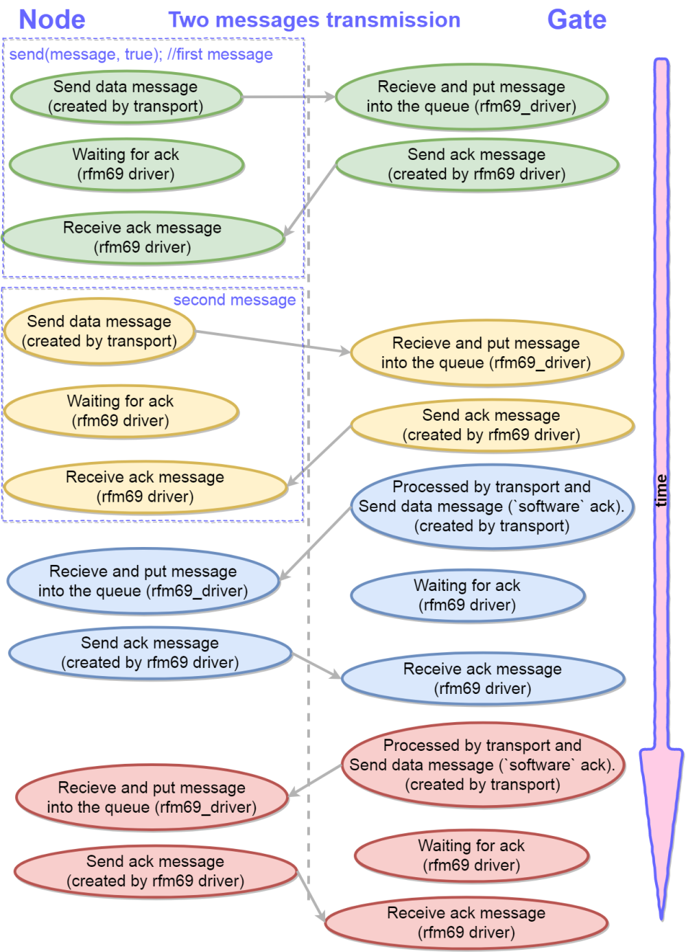
      I hope core team members will help me integrate this driver into the mainline code.

      Chapter 3. General recommendations and simple driver fixes.
      You can easily increase communication speed for the new driver. Just change on line in RFM69_new.h

      #define MY_RFM69_CSMA_LIMIT_DBM             (-95)			
      

      -95dbm is a VERY optimistic expected noise level for such popular frequency bands and amateur power supplies. I suggest use -90 or -85.

      It is foolish to send a message if the air is busy. But the new driver (and an old one, too as far as I remember) tries to send a message even if the air is busy (checks the air, waits for 500m… and sends 🙂 ). We should add some lines:

      //RFM69_new.cpp line 382 (before // set radio to standby to load fifo)
      if (!((hwMillis() - CSMA_START_MS) < MY_RFM69_CSMA_TIMEOUT_MS)){
        return false;
      }
      

      And of course it’s irrational to wait for an ACK if the message wasn’t sent. So we need replace one line to prevent it.

      //RFM69_new.cpp line 620 (before // radio is in RX)
      if (!RFM69_send(recipient, (uint8_t *)buffer, bufferSize, flags, !retry)){
      	continue;
      }
      

      Many thanks for reading this article till the end.

      posted in Development
      Koresh
      Koresh
    • RE: 💬 Wall Switch Insertable Node

      Oh.. Earlier I received cr2032 holders instead of cr2450. And now I've received cr2477 instead of cr2450... It's better, because it's possible to cut holders so they can be compatible with cr2450 battery 😛
      alt text

      And I'm ready to start mass testing 😃
      alt text

      posted in OpenHardware.io
      Koresh
      Koresh
    • RE: Very strange bugs. 2.3. RFM69.

      Yury and I have been digging deep into the new RFM69 driver and MySensors 2.3 for the past two days. I think it needs a lot of work so far. But good results have already been achieved 😄
      Now I can send lots of messages which requested ACK one by one without any wait between them (we tested 200 messages) and not a single NACK has ever appeared.
      Will share results soon.

      posted in Troubleshooting
      Koresh
      Koresh
    • RE: 💬 Just RFM gateway

      0_1489144301061_IMG_2017-03-10_133853.jpg
      It works! 😄
      Have uploaded some photos. Will share project sources soon 😉

      posted in OpenHardware.io
      Koresh
      Koresh
    • RE: 💬 Button size radionode

      So I am ready to present estimated prices to all my new boards.
      The estimate is too rough because I am not sure about size of the production batch. But it's better than nothing. Prices include pcb's, components and assembly. Configurations are not fully accepted yet.

      ---WALL SOCKET INSERTABLE NODE
      BASIC (ac/dc, atmega, rfm69, 10a relay) - 9.5$
      ADVANCED (ac/dc, atmega, rfm69, 10a relay, current sensor, rgb led) - 10.8$
      MAX (ac/dc, atmega, rfm69, 10a relay, currrent sensor, atsha204, watchdog, rgb led) - 12.2$

      ---WALL SWITCH INSERTABLE NODE
      BASIC (atmega, rfm69, buttons controller, JST wires) - 6.5$
      MAX (atmega, rfm69, buttons controller, JST wires, atsha204) - 7.5$

      --BUTTON SIZE RADIO NODE
      BASIC (atmega, rfm69) - 6$
      MAX (atmega, rfm69, atsha204) - 7$

      --SECRET TTL-USB
      BASIC - 1.4$

      posted in OpenHardware.io
      Koresh
      Koresh
    • RE: 💬 Wall Switch Insertable Node

      I've added SPI flash for OTA on this board too. And I've replaced 0402 components to 0603 so this board becomes not so crazy 😀
      alt text

      posted in OpenHardware.io
      Koresh
      Koresh
    • RE: 💬 MySensors Contest 2017

      alt text

      posted in Announcements
      Koresh
      Koresh
    • RE: 💬 MySensors Stable Node

      First small batch is completed 🙂
      0_1458050420487_DSC02594.JPG

      0_1458050451893_DSC02595.JPG

      0_1458050456651_DSC02596.JPG

      posted in OpenHardware.io
      Koresh
      Koresh
    • RE: 💬 Baby BusyCube design journal

      0_1501169507551_image-0-02-04-ddd00b913561a0c9d3a314a42c03d4c754930ff4880935f4ea3a247666839ded-V.jpg

      posted in OpenHardware.io
      Koresh
      Koresh
    • RE: Your workshop :)

      0_1459889199847_PANO_2016-02-17_153754.jpg
      😏

      posted in General Discussion
      Koresh
      Koresh
    • RE: [Solved] Strange behavior of RFM69 OTA burning firmware after some research

      Just 2 cents... We couldn't replicate 40 ms in retryWaitTime the mentioned above in another location. And tonight Yury couldnt replicate this case at home too. But yesterday it was typical situation. So I can assume it was caused by high environment radio noise (city center with many potential RF sources). I think it is an ideal situation to test boards and improve library stability 😉

      posted in Bug Reports
      Koresh
      Koresh
    • RE: 💬 Button size radionode

      Next revision 😏
      alt text

      posted in OpenHardware.io
      Koresh
      Koresh
    • RE: 💬 Wall Switch Insertable Node

      0_1491475913461_IMG_2017-04-06_131348.jpg
      Board works with nrf24 too 😉

      posted in OpenHardware.io
      Koresh
      Koresh
    • RE: 💬 Wall Switch Insertable Node

      I've prepared several kits for true soldering amateurs 😉
      0_1496003714688_DSC05694.jpg

      0_1496003724729_DSC05698.jpg

      0_1496003750490_DSC05701.jpg

      posted in OpenHardware.io
      Koresh
      Koresh
    • RE: 💬 Mini Relay Box

      I forgot to upload the photo of the completed device 😄
      0_1500505932798_relay_box.jpg

      posted in OpenHardware.io
      Koresh
      Koresh
    • RE: 💬 Baby BusyCube design journal

      Smart spinner 😄
      0_1503154085399_IMG_2017-08-02_111958.jpg
      Smart Spinner at the Baby BusyBox – 00:33
      — Жэка

      posted in OpenHardware.io
      Koresh
      Koresh
    • RE: 💬 EASY PIR multisensors box

      I applied a little improvement for the first small batch. Now we have two leds to show events 😉

      NRF version:
      0_1527197647541_IMG-325f5ee74fcbcad78e57119b2c6d7325-V.jpg
      0_1527197676134_pir_nrf_1.jpg

      RFM version:
      0_1527197664833_pir_nrf_3.jpg

      posted in OpenHardware.io
      Koresh
      Koresh
    • RE: In wall light switch node - Custom PCB

      @Xander said:

      For more than two switches see: http://www.gammon.com.au/forum/?id=11091
      I would add a hardware debouncing (R/C) to avoid the problems mentioned in the article.

      It's very good trick, but this circuit allows use of only tact switches. If you are interested - check my schematic (https://www.openhardware.io/view/102/Wall-Switch-Insertable-Node). It allows use of on\off switches too. I've drawn it after a little brainstorm 🙂 I'm not sure it is optimal, but it works very nice.

      posted in Hardware
      Koresh
      Koresh
    • RE: 💬 MySensors Stable Node

      @fisher Thanks. I'm looking for good PCBA service.

      posted in OpenHardware.io
      Koresh
      Koresh
    • RE: Better security without the need of a cryptoprocessor: out-of-band authentication

      @d00616 said in Better security without the need of a cryptoprocessor: out-of-band authentication:

      For long range sub GHz is the better choice. This is physics.

      You are right. But almost in every country RF laws allow to use 2.4G transmitters up to 100mw (+20dbm) without permitions. It would extend the range a lot.

      Please help by reporting the issues you have found, so we can create stable 32 bit platform support.

      I will try 😉

      posted in Feature Requests
      Koresh
      Koresh
    • RE: 💬 MySensors Stable Node

      @robosensor So far 9-10$ for each board. Small batch and not mass production soldering... Negotiating smd services for PCBA. Hope to reduce costs by $2 final. Will see what happens.

      posted in OpenHardware.io
      Koresh
      Koresh
    • RE: 💬 Wall Socket Insertable Node

      I'm having first success with this board. Power supply works!
      alt text

      posted in OpenHardware.io
      Koresh
      Koresh
    • RE: 💬 Wall Socket Insertable Node

      And some photos after soldering of the main components and slight washing.
      alt text

      alt text

      Relay trick 🙂
      alt text

      posted in OpenHardware.io
      Koresh
      Koresh
    • RE: 💬 Button size radionode

      Looks perfect with new usb-ttl. 😃 I plan to use this configuration as RFM69-USB gateway.
      alt text

      alt text

      posted in OpenHardware.io
      Koresh
      Koresh
    • RE: 💬 Button size radionode

      All my rfm69 boards family are under tests now 😃

      alt text

      posted in OpenHardware.io
      Koresh
      Koresh
    • RE: 💬 Button size radionode

      @scalz Challenge accepted 🙂 Now with OTA!
      alt text

      @frencho said:

      Koresh,
      Great work, I must say that I would be also interested in getting a couple of your boards as soon as they are ready !

      Thanks!

      posted in OpenHardware.io
      Koresh
      Koresh
    • RE: 💬 Button size radionode with sensors swarm extension

      @Anticimex said:

      @Koresh said:

      Can you a little clarify what do you mean? Schamatic of rfm69 module?

      I mean a link to where the module can be bought, and a link to some datasheet or similar, where the specification for the module footprint is so that it can be possible to make footprint in open source cad tools like kicad. Your design files looks like Altium.
      Of course you are welcome to contribute a footprint to the MySensors kicad repositories on github 🙂

      Thanks! Clear now 🙂 I will try convert all sourses to open formats and add more information to projects (documentation, design notes and components information) asap.

      posted in OpenHardware.io
      Koresh
      Koresh
    • RE: 💬 Wall Switch Insertable Node

      @Cliff-Karlsson
      Hope the batch of assembled boards (latest version after all fixes) will be ready in a week.

      posted in OpenHardware.io
      Koresh
      Koresh
    • RE: 💬 Button size radionode with sensors swarm extension

      @gohan Yes. Of course 😄

      posted in OpenHardware.io
      Koresh
      Koresh
    • RE: 💬 Wall Socket Insertable Node

      @PierreSt Many thanks for you attention to this project. I will add all assembled boards to Ebay next week. My devices successfully passed all safety tests. But unfortunatelly I have no enough resources to complete CE certification yet.

      posted in OpenHardware.io
      Koresh
      Koresh
    • RE: 💬 Jukebox design journal

      Finally solved a lot of problems and checked a lot of mistakes. But now the first version of this device works almost properly :trollface:
      0_1500843712763_IMG_2017-07-21_135230.jpg
      I will make a small report in the description asap 🙂

      posted in OpenHardware.io
      Koresh
      Koresh
    • RE: 💬 MultiRF MultiVoltage ProtoBox

      I am not sure this board is useful, but it works properly 😉
      0_1503566882454_MultiProtoBox_1.jpg

      0_1503566911484_MultiProtoBox_2.jpg

      posted in OpenHardware.io
      Koresh
      Koresh
    • RE: 💬 Button size radionode with sensors swarm extension

      @Miroslav-Kadaně I've just uploaded latest gerbers (rfm reset pin was connected to controller, connection of si1132 was fixed, reverse battery polarity protection was added). You can place PCB order at any factory. 😉

      posted in OpenHardware.io
      Koresh
      Koresh
    • RE: 💬 MySensors Nano RF shield

      It works nice 😉
      0_1513255369371_IMG_20171214_142845.jpg

      0_1513255375590_IMG_20171214_142919.jpg

      0_1513255382316_IMG_20171214_153522.jpg

      posted in OpenHardware.io
      Koresh
      Koresh
    • RE: 💬 EASY PIR multisensors box

      And final version of the enclosure 😃
      0_1528921238484_DSC06452.jpg
      It also has rubber 3d printed parts to protect the board from the environment but allow the sensor to work properly. Will show it later.

      posted in OpenHardware.io
      Koresh
      Koresh
    • RE: nRF5 action!

      @NeverDie Just my two cents. Leakage current through non ideal capacitors can be 1-10uA.

      posted in My Project
      Koresh
      Koresh
    • RE: Has anyone tried software reset of an Arduino?

      @Yveaux
      Watchdog is used by sleep() function in mysensors, so it is not possible to use it. Also it is not safe to use it on arduino boards with standard bootloader. If I need watchdog on standard arduino boards (without mysensors library) with standard bootloader I use next ISR to handle WDT interrupt

      // Watchdog Timer interrupt service routine. This routine is required
      // to allow automatic WDIF and WDIE bit clearance in hardware.
      ISR (WDT_vect)
      {
      	// WDIE & WDIF is cleared in hardware upon entering this ISR
      	wdt_disable();
      	asm volatile ("  jmp 0");
      }
      

      This ISR prevents bootloop.
      If I need just soft reset arduino I use the technique very similar to TheoL's

      asm volatile ("  jmp 0"); //call anywhere
      
      posted in Development
      Koresh
      Koresh
    • RE: 💬 MySensors Stable Node

      @Slorf I've left the package field in bom blank, so you can use any crystal you have. All components on the board are smd, so crystal should be smd too if you have it. But it may be difficult to place smd crystal as Q2 (too small area) and I've placed holes. I have both SMD and THD crystals but I will put holes in Q1 crystal pads in the next version too. Now you can simply mount THD crystal on the pads, it's not difficult.

      @Slorf said:

      Would it be possible to mount something like this on the pcb?

      It's possible. But I want this board to be as compact as possible.

      @ahmedadelhosni said:

      Great board.
      Did you test the performance ? Like number of recieved packets per second ?

      Thanks. I've tested stability (for some months without troubles in typical applications) and RF range. I think it doesn't make sense to test performance with low performance mcu, but you can propose the sketch and I test with it.

      posted in OpenHardware.io
      Koresh
      Koresh
    • RE: Nice push buttons?

      Tact buttons have limited life time. I came across buttons with 1million, 500 000, 100 000, 10 000 and 1000 switches. But be careful. Some buttons have life time of 500 or even 100 switches. It's perfect if supplier can tell you real buttons lifetime.

      posted in Hardware
      Koresh
      Koresh
    • RE: Has anyone tried software reset of an Arduino?

      @tekka
      Standard bootloader can fail to switch off wdt after reboot (on the boards with most chips) and it will cause bootloop. After rebooting watchog is still working and it is very important to disable it. We can use modified bootloader or bootloader like optiboot.

      posted in Development
      Koresh
      Koresh
    • RE: 💬 MySensors Stable Node

      @fisher The production of the first small batch is underway (manual mounting). So I wil have 20 boards for test next week. I will provide price estimate in a week.

      posted in OpenHardware.io
      Koresh
      Koresh
    • RE: irlz44n not fully open using 3.3V Arduino

      I tested this n-channel mosfet. It works fine (3.3v),

      posted in Hardware
      Koresh
      Koresh
    • RE: MySensors 2.3 and RFM69 new driver. Problems and solutions

      @jkandasa said in MySensors 2.3 and RFM69 new driver. Problems and solutions:

      @mfalkvidd @Yveaux Do we have any plan to implement this changes into MySensors mainline?

      We can intensively test this branch if it will appear.

      posted in Development
      Koresh
      Koresh
    • RE: 💬 MySensors Stable Node

      @GertSanders Thanks! 🙂

      @shabba I've almosted completed new ultrasmall radionode based on rfm69. I'am very busy now but I hope to finish all tests in a week. I will post board asap 🙂

      posted in OpenHardware.io
      Koresh
      Koresh
    • RE: Voltage divider for radio

      It's possible. But you must use small resistors because your "power source" should have relatively small output impedance. As a result you will warm up our planet a lot 🙂 Maximum consumption of the radio is 100mA. So I recommend using at least 10/6.6 ohm (1-2W) divider as "reliable" power source. 😏

      posted in Hardware
      Koresh
      Koresh
    • RE: Very strange bugs. 2.3. RFM69.

      I've written a small article https://forum.mysensors.org/topic/9484/mysensors-2-3-and-rfm69-new-driver-problems-and-solutions

      posted in Troubleshooting
      Koresh
      Koresh
    • RE: 💬 My simple RFM dongle for Serial GW

      @hek I recommend read both books 😉
      alt text

      posted in OpenHardware.io
      Koresh
      Koresh
    • RE: Meetup in the Netherlands - Saturday July 30th, in Breda!

      @Yveaux I hope I will make a presentation. I am too busy now too so I do not promise a thorough lecture. But I plan to share some hardware practices with my new boards as examples.

      posted in General Discussion
      Koresh
      Koresh
    • RE: OTA flash types for MySensors

      @Samuel235 said in OTA flash types for MySensors:

      AT45DB041E

      Hello. This chip (AT45DB041E) has no erase 32kb command (0x52), status read command has a strange opcode too (D7h). So it is no trivial task to use this chip.
      I can suggest Micron M25P40 as widespread IC. But it requires one trick and I will try to describe it. This chip has no erase 32kb command (0x52) too. It means OTA code will not erase memory and update will be failed. We (me and Yury) bumped into this problem when we started intensive tests of my nodes before production (we use micron M25P40). Moreover, when I try to investigate inexpensive avaliable chips I find an interesting thing. Chips with 64kb erase option (0xD8 opcode) are more common than chips with 32kb erase option (which support 64kb erase option too). So it can be worth adapting mysensors for use of any flash chip which supports 64kb erase option. To adapt your sketches you should do only two things

      1. Add this code into your sketch after including mysensors.h
      #define SPIFLASH_BLOCKERASE_32K   0xD8
      

      So OTA library will call erase 64kb command instead of erase 32kb command. It is very easy.
      2) You should use Bootloader which calls erase 64kb command instead of 32kb command.
      Bad news. It is not an easy task and you should recompile dual optiboot and burn it. 😧
      Good news. I've recompliled dual optiboot and all my nodes will burn with it by default. 😋

      My changes in bootloader are very simple but it sutable for my boards. We update it many many times and the process is absolutely bulletproof (especially after Tekka's update 👍 ).
      But how about a more universal solution? I think it is not too hard to modify dual optiboot to check flash first 10 bytes (OTA flag) after 32kb erase command call and try another command? I will try this idea later but may be someone will do it faster 😃

      posted in Hardware
      Koresh
      Koresh
    • RE: 💬 Button size radionode

      @bjornhallberg
      It sounds a little crazy but... we have enough space for eeprom in sot23-5 package (with decoupling capacitor!).
      I've placed 24LC64 temporarily😃
      alt text

      posted in OpenHardware.io
      Koresh
      Koresh
    • RE: Your workshop :)

      @scalz your workshop is really profesional. It is golden opportunity for infinitely creativity. And of course it is extremely clear. I am impressed 🙂

      posted in General Discussion
      Koresh
      Koresh
    • RE: Pir AS 312 with 2 rechargeable AAA battery. Boost needed?

      Hi. I use TPS61221DCKR for boards with such PIRs.

      posted in Hardware
      Koresh
      Koresh
    • RE: 💬 Wall Socket Insertable Node

      Unfortunately everything that could go wrong went wrong.
      So sample transformers are ready, sample boards are ready too. But I am expecting package with all my new boards and components only next week and hope to start testing soon.
      alt text

      posted in OpenHardware.io
      Koresh
      Koresh
    • RE: 💬 Wall Switch Insertable Node

      😃
      alt text
      alt text

      posted in OpenHardware.io
      Koresh
      Koresh
    • RE: 💬 Button size radionode

      @bjornhallberg said:

      @Koresh Where do you get the rfm69(h)w rev 3.0 from? Or is it the hc model? I can only seem to find rev 2 (?) on Ali?

      You can find these modules as "rfm69hc" on Ali. Do not forget about haggling 🙂

      I've received new version of these little boards 😃
      Will show new soldered boards asap.

      posted in OpenHardware.io
      Koresh
      Koresh
    • RE: 💬 Wall Switch Insertable Node

      And after mounting 🙂
      alt text

      alt text

      posted in OpenHardware.io
      Koresh
      Koresh
    • RE: 💬 Button size radionode

      @Cliff-Karlsson said:

      @Koresh Could you give us a rough estimate of the assembled price for the different nodes?

      I will try to estimate rough prices for all boards today.

      posted in OpenHardware.io
      Koresh
      Koresh
    • RE: 💬 Wall Socket Insertable Node

      @tonnerre33 do not worry. It will be in final version + we can use temperature sensor in rfm modult to switch of the relay.

      posted in OpenHardware.io
      Koresh
      Koresh
    • RE: 💬 MDMSGate

      Can you a little clarify how this device will work in mysensors environment? If I understand right this board has two uplink transport modules (rfm & nrf) and three gateway modules (standard serial, ethernet and wi-fi via ESP8266). So are you planning solder all of those modules on the board? I am not sure, but as I know we can use only one uplink transport (nrf ir rfm or rs485) and one gateway (serial/ethernet/wi-fi). So we can use only one of six possible configurations. May be it is not cost effective to solder all components at once?

      Thanks!

      PS
      Only one small suggestion from me. Your board contains only one chip with QFN package. It can raise PCBA price so it may be reasonable to use usb-ttl converter not in QFN\BGA package. But of course it's for you to decide 🙂

      posted in OpenHardware.io
      Koresh
      Koresh
    • RE: 💬 MySensors Stable Node V2

      I've added schematic and I'm open to any ideas according to this project 🙂

      posted in OpenHardware.io
      Koresh
      Koresh
    • RE: 💬 Wall Socket Insertable Node

      @jacikaas Thanks for your attention. Of course antenna is necessary, I use 17cm wire as antenna for all projects (so flexible antenna :))

      Unfortunately I was extremely busy last months. I became a father 👶 and I had a rush job with my work projects 😟 . But I hope I will have a little more time. Now I am waiting for the boards for the first relatively large batch of all my projects. I am waiting for the large pack of components too 😆 Also I found a reliable pcba partner (I hope). So I really hope to introduce my boards (preassembled) for purchase soon.
      Latest version of this board, for example looks as these screenshots:
      alt text
      alt text

      I also have very interesting new modifications of this and other boards (it is secret for now 😜 , but I will show it soon ).

      posted in OpenHardware.io
      Koresh
      Koresh
    • RE: 💬 Inexpensive 3.3V Boost Converter

      @NeverDie said:

      @scalz

      The schematic is from page 1 of the datasheet. So, yes, it fits the datasheet.

      As for efficiency, one has to ask: compared to what? And what are the trade-offs? In this instance, the component cost is very low, so that's the trade-off. There are certainly more efficient boost converters out there, but at greater cost. Also, some of the alternatives are more difficult to solder, so that's a consideration also.

      The application I'm considering it for is harvesting enough solar energy to power a TH sensor mote. I have no prior experience in doing that, so I'm planning to try a number of different boost converters to empirically test which is "sufficient." If this proves to be sufficient, then it will win on cost (at least compared to the other boost converters that I'll be testing).

      Anyhow, if you know of a more efficient or "better" boost converter, but which costs less, then I'd be interested to know. In fact, I'd be interested in any boost converter that costs less, even if it has worse efficiency.

      I am sorry for interfering, I'll just try to add my 5 cent 🙂 To my opinion, the most effective converter - no converter 🙂 I came to this conclusion when I made calculations with the most effective contemporary convertors IC with coin batteries (2032, 2450, 2477). These batteries have very high output impedance after voltage drops below 1.8-2.0v and they have very low residual capacity in this case. Of course my conclusion can be wrong for other large batteries with other discharge curve. 😃

      posted in OpenHardware.io
      Koresh
      Koresh
    • RE: 💬 Button size radionode with sensors swarm extension

      Already shared 😉

      posted in OpenHardware.io
      Koresh
      Koresh
    • RE: 💬 Button size radionode with sensors swarm extension

      @Nca78 said:

      @Koresh said:

      Do not worry, I will share software source code

      Thank you but I was just asking for the name of the design software to have a closer look at the board. Altium it seems so I can't have a look at your routing 😞
      Was curious to see the details closer as you seem to squeeze 2 routes through the corner of the atmega, I can't do that with my current settings.

      This board was routed according 5mil width/5mil clearance rules.

      posted in OpenHardware.io
      Koresh
      Koresh
    • RE: 💬 MyMultisensors

      Unfortunately this circuit and pcb contain a little mistake in reverse polarity protection module. Q1 must be connected as on the following diagram
      reverse polarity
      So just reverse connections of drain and source of Q1, and the next version of your board will contain correct reverse polarity protection 😉
      PS
      Otherwise your circuit will be powered through mosfet body diode (with a drop to ~0.6V of course) when polarity is crossed. 😧

      posted in OpenHardware.io
      Koresh
      Koresh
    • RE: 💬 Button size radionode with sensors swarm extension

      @Cliff-Karlsson The local factory starts assembly today (button size node, insertable switch node, wall socket insertable node and mini relay box). ETA is one-two week (max).
      This board is avaliable with two radios - rfm69hw and rfm69cw (with adapter shown below). Price will be the same. Which radio is preferred for you? If you plan to use this board with battery I suggest to use rfm69cw module to extend battery life (it has lower but enouogh power and works down to ~2V).

      0_1490689193824_rfm69cw_adapter.png

      posted in OpenHardware.io
      Koresh
      Koresh
    • RE: 💬 Wall Switch Insertable Node

      @Samuel235 said in 💬 Wall Switch Insertable Node:

      @Koresh - Do you happen to have a link for the JST connectors? I can't seem to find any at a reasonable price at the moment. And the male side too, if you don't mind me asking 🙂

      The price depends on a batch size. You can try to ask any supplier on ali for 100-200 pcs and may be price will be reasonable 🙂

      posted in OpenHardware.io
      Koresh
      Koresh
    • RE: 💬 Wall Socket Insertable Node

      @DavidZH Sorry for such long delay with this question. I will try to explain it carefully now.
      I think it is not possible to buy ready transformer on ali or anywhere else. You can only derive it yourself according to your schematic and produce it at any factory according to your requirements.
      This board has flyback power supply so you can use any flyback transformer design guide, or use as similar as possible reference design. I used EBC10010 reference design to produce the required transformer.
      The main difficulty is the difference between theoretical transformers and produced transformers, so we should tune our schematic to produced transformer a little. Now I have a small batch of transformers almost all of which are soldered on the boards. When I place an order for the next batch of transformers (may be a larger one), I can who send it to anyone who is interested (of course with a tuned schematic if the next batch is different).

      posted in OpenHardware.io
      Koresh
      Koresh
    • RE: 💬 Micro (nano) ampere meter (double)

      I like it! Great work! 🙂
      I realized this idea nearly year ago, but I am so lazy... so I didn't post it )
      This is my variant:
      0_1493204825884_IMG_2017-04-26_110025.jpg
      I can make some suggestions.
      We can add a switch which will short inputs sometimes for automatic calibration. I used sealed contact relay.
      It is not clear for me how you realize input offset (input signal of HX711 should be between AGND+1.2 and AVDD-1.3 according HX711 datasheet. So I do it in the following way which is not optimal but easy:
      0_1493206665757_measure1.png

      posted in OpenHardware.io
      Koresh
      Koresh
    • RE: 💬 Wall Switch Insertable Node

      Unfortunately I can't open my ebay shop right now. While I'm trying to open it, you can buy this board here: https://www.ebid.net/eu/for-sale/arduino-ide-compatible-coincell-powered-switch-controller-rfm69cw-433-mhz-radio-156694971.htm

      posted in OpenHardware.io
      Koresh
      Koresh
    • RE: 💬 Button size radionode with sensors swarm extension

      @Cliff-Karlsson
      @bjornhallberg
      I have some assembled boards without the radio. You can buy them here https://www.ebid.net/eu/for-sale/arduino-ide-compatible-coincell-powered-controller-ready-for-rfm69cw-hcw-radio-156711327.htm . I just reminding this board has a rfm69HCW footprint but you can solder rfm69CW modules with the pcb adapter which I made. Of course I will supply the adapter with the main board.

      posted in OpenHardware.io
      Koresh
      Koresh
    • RE: 💬 Button size radionode with sensors swarm extension

      @bjornhallberg
      I have some insertable switch boards without radio. I planned to solder nrf24 into them but can sell them without radio too (it supports only cw modules). Will put up for sale soon.

      posted in OpenHardware.io
      Koresh
      Koresh
    • RE: 💬 My Slim 2AA Battery Node

      Internal pull-up resistors have 20-50k resistance. It may be not enough.

      posted in OpenHardware.io
      Koresh
      Koresh
    • RE: 💬 Adjustable Boost Converter with Pass-Through

      @NeverDie It is much easier to solder the wire to pads with relief connection than the wire to directly connected pads. Your soldering point even can be unreliable if your pad is directly connected to very huge polygon and your soldering iron don't have enough power.

      posted in OpenHardware.io
      Koresh
      Koresh
    • RE: 💬 MySensors Easy Pro Mini

      First version of this board does not contain mistakes and works properly. I will remove "work in progress" mark after some tests soon. 😄
      0_1503427277388_easy_pro_mini1.jpg

      posted in OpenHardware.io
      Koresh
      Koresh
    • RE: 💬 MultiRF MultiVoltage ProtoBox

      This board fits the box good 😉
      0_1507293417863_DSC06257.png
      0_1507293389221_DSC06258.png

      posted in OpenHardware.io
      Koresh
      Koresh
    • RE: 💬 MultiRF MultiVoltage ProtoBox

      @NeverDie said in 💬 MultiRF MultiVoltage ProtoBox:

      Nice work! It looks like a commercial product.

      Thanks a lot for your high appraisal of this device. I designed this board just for fun but now I really like it with this enclosure. I would plan to improove this board a little (omit unnecessary functions and add useful features) and to start production of this device.

      @NeverDie said in 💬 MultiRF MultiVoltage ProtoBox:

      What about the antenna?

      I use very simple solution for all my boards. I just solder wire and fix it with glue pen to the board to improve reliability. Not very ideal for 433MHz board (~20cm) but perfect for 868MHz (~10cm). By the way I tested different modules with Yury (433/866). we found 868Mhz optimal frequency. Excellent range (up to 10x compareble to NRF) and very good feedthrough. So may be it is the most optimal rf solution.

      @MiKa said in 💬 MultiRF MultiVoltage ProtoBox:

      And which battery? Small 250 mAh Li-ion?

      May be. With usb and onboard charger of course 😉

      @gohan said in 💬 MultiRF MultiVoltage ProtoBox:

      may I ask how did you solder all the small SMD parts?

      I soldered all of my prototypes by hand. I use simple soldering gun and flux. All boards batches are assembled on the factory of course (manually or automatic, depends on the batch size).

      @gohan said in 💬 MultiRF MultiVoltage ProtoBox:

      Maybe this could fit
      https://www.aliexpress.com/item/10Pcs-433MHz-Helical-Antenna-2-5dBi-32mm-for-Remote-Contorl/32608690665.html

      I really do not recommend to use springs like this. It is not antenna it is... mechanical spring. I tried to use many of them and all of them are much worse compareble with single wire antenna. It has very bad characteristic. 👎 I verified it in modeling software and in real life.

      posted in OpenHardware.io
      Koresh
      Koresh
    • RE: 💬 MultiRF MultiVoltage ProtoBox

      @NeverDie Sorry for delay... This is example (improved version with 3d printed fixer)
      0_1507817311955_IMG_2017-10-12_165821.jpg
      0_1507817329009_IMG_2017-10-12_165833.jpg

      posted in OpenHardware.io
      Koresh
      Koresh
    • RE: 💬 Button size radionode with sensors swarm extension

      There are so many reasons to use two CR2032 batteries in series with power converter instead of one lager battery like 2450
      -CR2032 are much more widespread batteries
      -Wider temperature range
      -Stable voltage during all battery lifetime (using voltage converter)
      -Stable radio power during battery lifetime
      -Batteries give less current during transmitting so they are not "shocked" by high current.

      So I plan to create version with two CR2032 batteries holder (like on the Yury's photo) and the ultra high efficiency DC-DC converter based on the tps62745 (400 nA quiescent current, 90% efficiency)
      0_1513520436859_2017-12-17_16-39-45.png
      😉

      posted in OpenHardware.io
      Koresh
      Koresh
    • RE: 💬 Button size radionode with sensors swarm extension

      New version with double battery holder and power convertor works nice.
      Power consumption in sleep mode is less than 9uA 😃
      0_1521106765289_buttonsize_6v_1.jpg

      0_1521106812358_buttonsize_6v_2.jpg

      I will test it soon..

      posted in OpenHardware.io
      Koresh
      Koresh
    • RE: 💬 Mini Dimmer Box

      0_1522495409624_IMG_20180328_162046.jpg

      0_1522495479110_IMG_20180328_162106.jpg

      posted in OpenHardware.io
      Koresh
      Koresh
    • RE: 💬 EASY PIR multisensors box

      @nca78 I bought these sensors for prototype boards in the local store ( http://www.pcmount.by/catalog/radiokomponenty/mikroshemy/ic-pir-s16-l201d )

      posted in OpenHardware.io
      Koresh
      Koresh
    • RE: 💬 Button size radionode with sensors swarm extension

      First batch of the latest version is ready 😉
      0_1527575686651_buttonsize_6v.jpg
      0_1527575726685_enclosure_1.jpg
      0_1527575693420_buttonsize_6v_back.jpg
      0_1527575701056_buttonsize_6v_back2.jpg

      posted in OpenHardware.io
      Koresh
      Koresh
    • RE: 💬 Button size radionode with sensors swarm extension

      Hi @bjornhallberg.
      I've done many tests today with your code. All tested boards were the newer ones. So I completely had no ideas until I read your last message. Now all is clear for me. You have battery draining ~10-100ua, not 1-2mA. As I see your boards contain 107J capacitors. It was an absolutely failed batch of capacitors. We resoldered all of these capacitors on all the boards after we had found this problem with @alexsh1. Unfortunatelly some of these boards had been sent until we found this problem. We are so sorry you had to deal with these failed boards. I suggest I send you some new tested buttonsized v1 boards to you. Also I can send good capacitors to rework failed boards and some of my new interesting boards for free.

      posted in OpenHardware.io
      Koresh
      Koresh