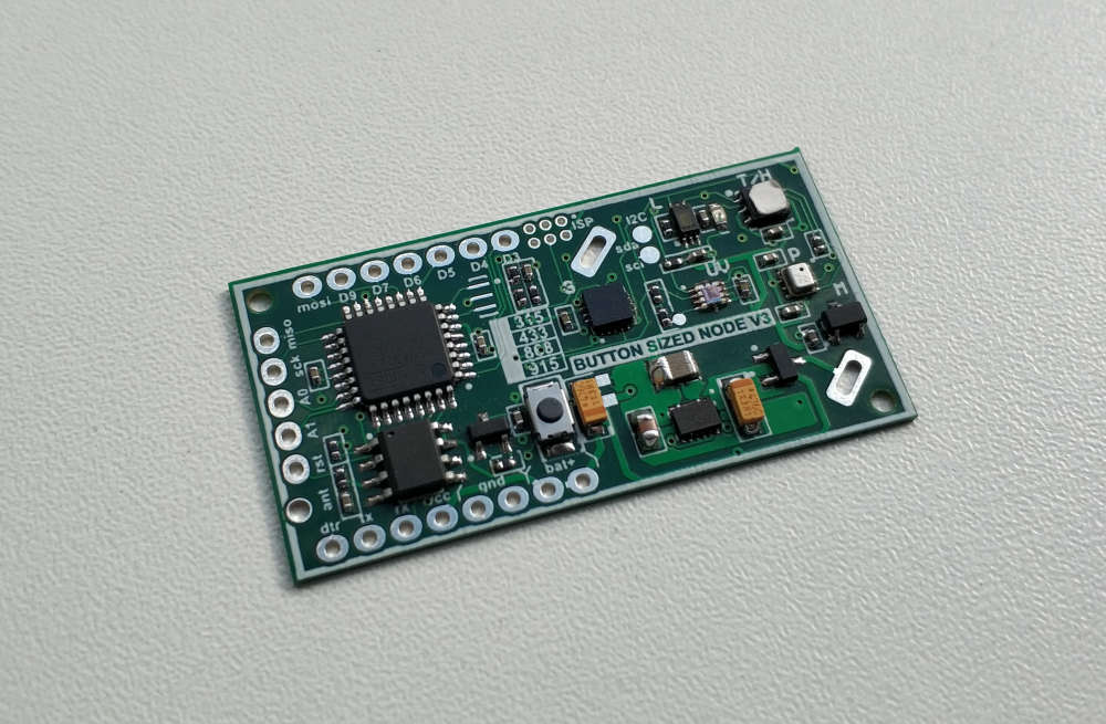
Hope will test the new version of this universal board soon. Now it has additional inexpensive accelerometer, magnetic sensor, led, reset button, multifootprint for lora/hw/cw radio without adapter and improoved 4layers design
Posts made by Koresh
-
RE: π¬ Button size radionode with sensors swarm extension
-
RE: Pir AS 312 with 2 rechargeable AAA battery. Boost needed?
Hi. I use TPS61221DCKR for boards with such PIRs.
-
RE: π¬ Button size radionode with sensors swarm extension
@christoph-blank Hi, thanks for using this board. In the first version of this board the divider is conected after LDO, so you can't measure voltage above 3.3V. In the second version the divider is connected to the battery directly. You use 3.2v battery so it is not problem for you. But LiFePo4 battery has very flat discharge curve so it can be hard to read this level with reasonable accuracy.
I will try to find LiFePo4 battery and add some piece of code soon. Yet you can play with followed code// Get the battery Voltage int sensorValue = analogRead(BATTERY_SENSE_PIN); // 1M, 470K divider across battery and using internal ADC ref of 1.1V1 // ((1e6+470e3)/470e3)*1.1 = Vmax = 3.44 Volts /* The MySensors Lib uses internal ADC ref of 1.1V which means analogRead of the pin connected to 470kOhms Battery Devider reaches * 1023 when voltage on the divider is around 3.44 Volts. 2.5 volts is equal to 750. 2 volts is equal to 600. * RFM 69 CW works stable up to 2 volts. Assume 2.5 V is 0% and 1023 is 100% battery charge * RFM 69 HCW works stable up to 2.5 volts (sometimes it can work up to 2.0V). Assume 2.5 V is 0% and 1023 is 100% battery charge * 3.3V ~ 1023 * 3.0V ~ 900 * 2.5V ~ 750 * 2.0V ~ 600 */ #ifdef MY_IS_RFM69HW int batteryPcnt = (sensorValue - 750) / 1.5; #else int batteryPcnt = (sensorValue - 600) / 3; #endif
-
RE: π¬ Button size radionode with sensors swarm extension
Hi @bjornhallberg.
I've done many tests today with your code. All tested boards were the newer ones. So I completely had no ideas until I read your last message. Now all is clear for me. You have battery draining ~10-100ua, not 1-2mA. As I see your boards contain 107J capacitors. It was an absolutely failed batch of capacitors. We resoldered all of these capacitors on all the boards after we had found this problem with @alexsh1. Unfortunatelly some of these boards had been sent until we found this problem. We are so sorry you had to deal with these failed boards. I suggest I send you some new tested buttonsized v1 boards to you. Also I can send good capacitors to rework failed boards and some of my new interesting boards for free. -
RE: π¬ Button size radionode with sensors swarm extension
@diogoc I will try to find them. But all of components are 0402...
-
RE: π¬ Button size radionode with sensors swarm extension
@gerator Oh.. so sorry. It is new forum reporting system. Didn't saw your message.
A6 reads unregulated voltage (3.5-6.5V) through divider (1/3). So it can't destroyed nothing. -
RE: MySensors 2.3 and RFM69 new driver. Problems and solutions
@jkandasa said in MySensors 2.3 and RFM69 new driver. Problems and solutions:
@mfalkvidd @Yveaux Do we have any plan to implement this changes into MySensors mainline?
We can intensively test this branch if it will appear.
-
RE: AC-DC at own
@axillent I can't see the gerbers or sources of the latest board (din shape). I've seen your transformers on ali. It is perfect. I need auxiliary coil for my projects so I should place custom order on the factory.
-
RE: AC-DC at own
@axillent greate work ! It is very hard to order transformers... My congratulations! Can you share the pcb for the review ?
-
RE: MOSFET as relay to keep ESP on until GPIO is low
Add 10k resistor between the gpio5 and main gnd.
-
RE: π¬ Button size radionode with sensors swarm extension
@pepson
pcb2.* - main boards gerbers
rfm69c_to_rfm69hc.* - adapter gerbers
You need only main board gerbers -
RE: π¬ Button size radionode with sensors swarm extension
@pepson said in Button size radionode with sensors swarm extension:
Failed load project to production.
You mixed gerbers of the main board and adapter board.
@pepson said in Button size radionode with sensors swarm extension:
Please share also layer describe...
It is standard. If you really need it you can find layers description here
https://goo.gl/Jv33Lb (Generated Gerber Files)@pepson said in Button size radionode with sensors swarm extension:
Can you share your project file and file gerber with this specification
No I can't. Have no time today, sorry.
-
RE: π¬ Button size radionode with sensors swarm extension
@pepson Yes. So it have longer lifetime, radio range and working temperature range.
-
RE: π¬ Button size radionode with sensors swarm extension
@pepson Yes. radio footprints are the same. You can use HW or CW via adapter.
-
RE: π¬ Button size radionode with sensors swarm extension
@pepson said in Button size radionode with sensors swarm extension:
And what is ButtonSizeNode_V2 (with dc-dc) ?? What is diffrent to v1 ?
https://github.com/EasySensors/ButtonSizeNode
https://github.com/EasySensors/ButtonSizeNode2@pepson said in Button size radionode with sensors swarm extension:
But please share a list element what capacity and resistor and other and with what body. Ex 0805 etc.
Will try to share soon. Almost all elements are 0402.
-
RE: π¬ Button size radionode with sensors swarm extension
@pepson said in Button size radionode with sensors swarm extension:
And what is size gold pins ? 2.54 ?
Yes, 2.54
@pepson said in Button size radionode with sensors swarm extension:
And anybody what pin should be wire to activate programming... ? In arduino pro mini is dedicated micro switch. In this dont have microswitch and i want add microswitch. It should be RST connected to GND ? please help...
Programming is activated via DTR pin automatically.
@pepson said in Button size radionode with sensors swarm extension:
Can you share elemnts for version RFM69HW ? I see only PCB files but i dont know whatr i must have elements...
Schematic of the first version is available. Will share schematic version of ButtonSizeNode_V2 (with dc-dc) later.
-
RE: MySensors 2.3 and RFM69 new driver. Problems and solutions
I've forked mys to share draft transport and rfm driver. It is avaliable here
@mfalkvidd
Thanks. You answered to your question according the memory yourself -
MySensors 2.3 and RFM69 new driver. Problems and solutions
Hi everyone. I want to share the results of a small investigation into MySensors 2.3 and rfm69 new driver environment. I decided to do it after I bumped into some problems.
I hope it will be interesting for everyone. Newbies can find simple recommendations to improve MySensors stability. Experienced users end core team members can implement my ideas into the mainline version in the right way.
Let me remind you of the problem briefly. If you try to run this code to send two messages from the node to gateway only the first message will be sent properly.send(message1, true); send(message2, true);
Chapter 1. Second ACK
Letβs see how mysensors with rfm69 processes incoming messages. Just when rfm69 receives the message, it generates interrupt which is handled by rfm69 driver. Butβ¦ in this interrupt the driver does not process the message. It only sets RFM69_irq flag.// IRQ handler: PayloadReady (RX) & PacketSent (TX) mapped to DI0 LOCAL void RFM69_interruptHandler(void) { // set flag RFM69_irq = true; }
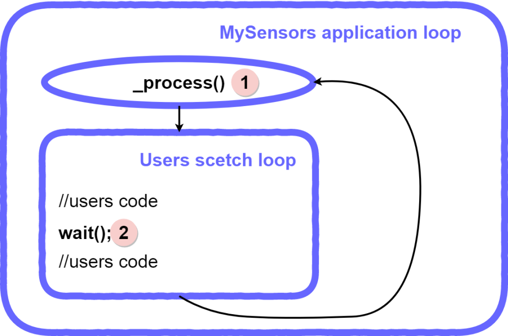
Later process() function reads this flag and reads messages from rfm69. So the first important point. Incoming messages can be processed only in two places of application code:
- Inside the process() function at the beginning of the main mysensors application loop.
- Inside the wait() function anywhere you call it (it actually calls the process() function too).
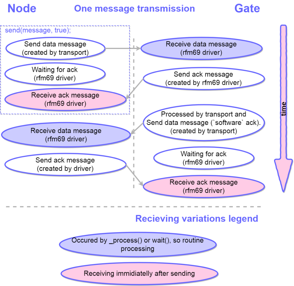
There is only one exception to this rule. Just when you send any message with ACK request, the rfm69 driver is waiting for the ACK message. So at this moment your application can get a message too. If it is an expected ack it will be processed, otherwise β just received and not processed.Now we know a little more about how mysensors processes incoming messages and I will try to describe how a very simple usecase works. Letβs imagine that the node sends one message to the gateway
send(message1, true);
In the following diagram I tried to explain in detail the behavior of the application from both sides β gateway and the node.
As you can see this case works properly.
Now we can imagine a more complex case. The node sends two messages to the gateway one by one.send(message1, true); send(message2, true);
Yes this is the same code which I wrote at the start of this topic. So the next diagram describes how it works.
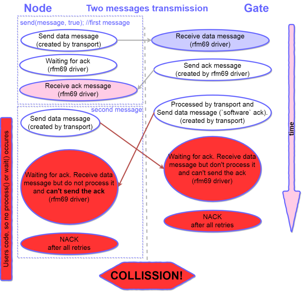
Oopsβ¦ The second ACK will break the communication in this case? Yes β 99% it causes the problems. But why is this second ACK needed at all? I am not entirely sure, but I will try to explain my understanding of this second ack (how it should work).
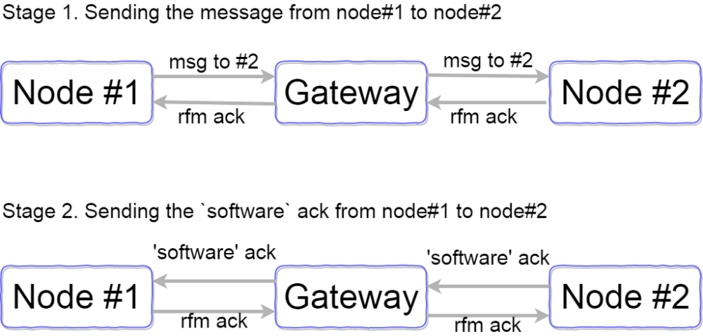
So this second ACK theoretically can help you know if your message was delivered to the node which is behind the gate. But in real life it brakes the communication.
How can we fix it? How can we send two messages one by one without collision? I will describe some solutions.
First solution is very simple but very bad and I strongly recommend against implementing it. Just add wait(100) between the linessend(message1, true); wait(100); send(message2, true);
Why is this solution bad? First it causes a dramatic rise in battery consumption. There are two messages in this case. If you want to send 4-5 messages our sketch will work 400ms longer! Second it is absolutely wrong from the application design point. We are trying to fix the transport layer error on the user application layer. So implement this solution as last resort.
Second solution is not a very good one but I would recommend it for anyone who uses simple mysensors setups with relatively simple sketches without any complicated customization. Just disable the second ACK!
//MyTransport.cpp line723 // send ACK, use transportSendRoute since ACK reply is not internal, i.e. if !transportOK do not reply #ifndef MY_RADIO_RFM69 (void)transportSendRoute(_msgTmp); #endif
or just comment it
// send ACK, use transportSendRoute since ACK reply is not internal, i.e. if !transportOK do not reply //(void)transportSendRoute(_msgTmp);
This simple hack will increase your network speed and reliability sharply. For example this code
for (int m = 1; m < 200; m ++){ send(msg_sw.set(m), true); }
will send 200 messages with ACK requests one by one and not a single NACK has ever appeared. I tried it many times.
What do you lose if you implement this solution? You will not see this message45899 TSF:MSG:READ,0-0-144,s=1,c=1,t=2,pt=1,l=1,sg=0:0 45905 TSF:MSG:ACK
in the debug serial output of the node. I think 95% of users do not process such messages in the sketch and it is not a big loss.
If you want to process these ACK messages to check the delivery to the node which is behind the gate you can implement the third more clever solution// send ACK, use transportSendRoute since ACK reply is not internal, i.e. if !transportOK do not reply #ifndef MY_RADIO_RFM69 #ifndef MY_GATEWAY_FEATURE (void)transportSendRoute(_msgTmp); #endif #endif
Or
// send ACK, use transportSendRoute since ACK reply is not internal, i.e. if !transportOK do not reply #ifndef MY_RADIO_RFM69 if (_msg.last != _msg.sender){ (void)transportSendRoute(_msgTmp); } #endif
It makes your network more stable too. In the first example we disable
software
ACK (second ACK) from the gateway to the node. In the second example we disablesoftware
ACK from one node to another node if there are no nodes between them (I havenβt tested this case but It can work).But imagine you do not want to implement this hack at all. How can we fix this problem differently? Letβs move to the next chapter.
Chapter 2. The queue of the messages.
The messages queue is standard in different systems. It is nonsense to omit this feature in a serious system. Moreover, MySensors team implements this feature⦠but for NRF24 not for RFM69.
I will not describe in detail how message queue works. You only should know that received messages are read immediately after they are received (inside the interrupt handler) and put into the queue. They can be processed later but we do not omit a single one.
I will try to implement queue message for the RFM69 transport and drivers level. I have a very good example for NRF24 so it was not very hard. I bumped only into one serious problem (yet:)). NRF24 driver uses autoACK function, which is not supported by rfm69. If we want to send ACK inside the interrupt handler we canβt use time system functions (millis(), delay() and so on). So I implement Ack sending function without forbidden functions.
You can see my draft solution on the easysensors github (will share soon, may be today). Most of the changes are in the MyTransportRF24.cpp and RFM69_new.cpp. If you want to try it you should also remove mysensors capabilities protection like this in some places#if defined(MY_RADIO_RFM69) #error Receive message buffering not supported for RFM69! #endif
I havenβt tested it thoroughly. But I have tested it to check if Β«DOUBLE ACKΒ» problem is solved. And yes β it is solved. The next diagram shows how this code works with my new transport and driver
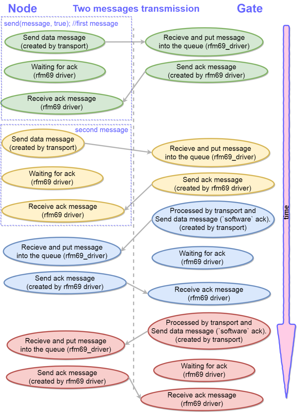
I hope core team members will help me integrate this driver into the mainline code.
Chapter 3. General recommendations and simple driver fixes.
You can easily increase communication speed for the new driver. Just change on line in RFM69_new.h#define MY_RFM69_CSMA_LIMIT_DBM (-95)
-95dbm is a VERY optimistic expected noise level for such popular frequency bands and amateur power supplies. I suggest use -90 or -85.
It is foolish to send a message if the air is busy. But the new driver (and an old one, too as far as I remember) tries to send a message even if the air is busy (checks the air, waits for 500m⦠and sends ). We should add some lines:
//RFM69_new.cpp line 382 (before // set radio to standby to load fifo) if (!((hwMillis() - CSMA_START_MS) < MY_RFM69_CSMA_TIMEOUT_MS)){ return false; }
And of course itβs irrational to wait for an ACK if the message wasnβt sent. So we need replace one line to prevent it.
//RFM69_new.cpp line 620 (before // radio is in RX) if (!RFM69_send(recipient, (uint8_t *)buffer, bufferSize, flags, !retry)){ continue; }
Many thanks for reading this article till the end.
-
RE: Very strange bugs. 2.3. RFM69.
Yury and I have been digging deep into the new RFM69 driver and MySensors 2.3 for the past two days. I think it needs a lot of work so far. But good results have already been achieved
Now I can send lots of messages which requested ACK one by one without any wait between them (we tested 200 messages) and not a single NACK has ever appeared.
Will share results soon. -
RE: Very strange bugs. 2.3. RFM69.
@bakcsa Excuse me... Do you understand what CSMA means? The air in all tests was absolutely avaliable. So we have a bugs in ideal conditions (dot to dot connection without cramps).
-
Very strange bugs. 2.3. RFM69.
Today I've tried to solve very simple task using my nodes. I've tried to use new 2.3 core. Unfortunately I bumped with very strange bugs and put off my task to investigate mysensors behaviour a little. I think I bumped with big software problems and I try to described it very detailed.
Network topology is very simple. I tried two variants:
- Vell tested PIR node + basic RFM serial gateway.
- Pir node (exactly the same board) + basic ESP8266 to MQTT gateway.
Nodes uses RFM69 868Mhz radio. I'm sure hardware works propery.
I used basic mysensors configuration without any changes (I've downloaded it today to the clear virtual machine).
Code of the SERIAL gateway:
/** * The MySensors Arduino library handles the wireless radio link and protocol * between your home built sensors/actuators and HA controller of choice. * The sensors forms a self healing radio network with optional repeaters. Each * repeater and gateway builds a routing tables in EEPROM which keeps track of the * network topology allowing messages to be routed to nodes. * * Created by Henrik Ekblad <henrik.ekblad@mysensors.org> * Copyright (C) 2013-2015 Sensnology AB * Full contributor list: https://github.com/mysensors/Arduino/graphs/contributors * * Documentation: http://www.mysensors.org * Support Forum: http://forum.mysensors.org * * This program is free software; you can redistribute it and/or * modify it under the terms of the GNU General Public License * version 2 as published by the Free Software Foundation. * ******************************* * * DESCRIPTION * The ArduinoGateway prints data received from sensors on the serial link. * The gateway accepts input on serial which will be sent out on radio network. * * The GW code is designed for Arduino Nano 328p / 16MHz * * Wire connections (OPTIONAL): * - Inclusion button should be connected between digital pin 3 and GND * - RX/TX/ERR leds need to be connected between +5V (anode) and digital pin 6/5/4 with resistor 270-330R in a series * * LEDs (OPTIONAL): * - To use the feature, uncomment any of the MY_DEFAULT_xx_LED_PINs * - RX (green) - blink fast on radio message received. In inclusion mode will blink fast only on presentation received * - TX (yellow) - blink fast on radio message transmitted. In inclusion mode will blink slowly * - ERR (red) - fast blink on error during transmission error or receive crc error * */ // Enable debug prints to serial monitor #define MY_DEBUG // Enable and select radio type attached //#define MY_RADIO_NRF24 //#define MY_RADIO_NRF5_ESB #define MY_RADIO_RFM69 //#define MY_RADIO_RFM95 // Set LOW transmit power level as default, if you have an amplified NRF-module and // power your radio separately with a good regulator you can turn up PA level. //#define MY_RF24_PA_LEVEL RF24_PA_LOW #define MY_RFM69_FREQUENCY RFM69_868MHZ //#define MY_RFM69_FREQUENCY RFM69_433MHZ // Enable serial gateway #define MY_GATEWAY_SERIAL // Define a lower baud rate for Arduinos running on 8 MHz (Arduino Pro Mini 3.3V & SenseBender) #if F_CPU == 8000000L #define MY_BAUD_RATE 38400 #endif // Enable inclusion mode #define MY_INCLUSION_MODE_FEATURE // Enable Inclusion mode button on gateway //#define MY_INCLUSION_BUTTON_FEATURE // Inverses behavior of inclusion button (if using external pullup) //#define MY_INCLUSION_BUTTON_EXTERNAL_PULLUP // Set inclusion mode duration (in seconds) #define MY_INCLUSION_MODE_DURATION 60 // Digital pin used for inclusion mode button //#define MY_INCLUSION_MODE_BUTTON_PIN 3 // Set blinking period #define MY_DEFAULT_LED_BLINK_PERIOD 300 // Inverses the behavior of leds //#define MY_WITH_LEDS_BLINKING_INVERSE // Flash leds on rx/tx/err // Uncomment to override default HW configurations //#define MY_DEFAULT_ERR_LED_PIN 4 // Error led pin //#define MY_DEFAULT_RX_LED_PIN 6 // Receive led pin //#define MY_DEFAULT_TX_LED_PIN 5 // the PCB, on board LED #include <MySensors.h> void setup() { // Setup locally attached sensors } void presentation() { // Present locally attached sensors } void loop() { // Send locally attached sensor data here }
Code of the ESP8266 MQTT gateway
/** * The MySensors Arduino library handles the wireless radio link and protocol * between your home built sensors/actuators and HA controller of choice. * The sensors forms a self healing radio network with optional repeaters. Each * repeater and gateway builds a routing tables in EEPROM which keeps track of the * network topology allowing messages to be routed to nodes. * * Created by Henrik Ekblad <henrik.ekblad@mysensors.org> * Copyright (C) 2013-2015 Sensnology AB * Full contributor list: https://github.com/mysensors/Arduino/graphs/contributors * * Documentation: http://www.mysensors.org * Support Forum: http://forum.mysensors.org * * This program is free software; you can redistribute it and/or * modify it under the terms of the GNU General Public License * version 2 as published by the Free Software Foundation. * ******************************* * * REVISION HISTORY * Version 1.0 - Henrik Ekblad * * DESCRIPTION * The ESP8266 MQTT gateway sends radio network (or locally attached sensors) data to your MQTT broker. * The node also listens to MY_MQTT_TOPIC_PREFIX and sends out those messages to the radio network * * LED purposes: * - To use the feature, uncomment any of the MY_DEFAULT_xx_LED_PINs in your sketch * - RX (green) - blink fast on radio message received. In inclusion mode will blink fast only on presentation received * - TX (yellow) - blink fast on radio message transmitted. In inclusion mode will blink slowly * - ERR (red) - fast blink on error during transmission error or receive crc error * * See https://www.mysensors.org/build/connect_radio for wiring instructions. * * If you are using a "barebone" ESP8266, see * https://www.mysensors.org/build/esp8266_gateway#wiring-for-barebone-esp8266 * * Inclusion mode button: * - Connect GPIO5 (=D1) via switch to GND ('inclusion switch') * * Hardware SHA204 signing is currently not supported! * * Make sure to fill in your ssid and WiFi password below for ssid & pass. */ // Enable debug prints to serial monitor #define MY_DEBUG // Use a bit lower baudrate for serial prints on ESP8266 than default in MyConfig.h #define MY_BAUD_RATE 9600 // Enables and select radio type (if attached) //#define MY_RADIO_NRF24 #define MY_RADIO_RFM69 //#define MY_RADIO_RFM95 #define MY_RFM69_FREQUENCY RFM69_868MHZ // Define for frequency setting. Needed if you're radio module isn't 868Mhz (868Mhz is default in lib) //#define MY_IS_RFM69HW // Mandatory if you radio module is the high power version (RFM69HW and RFM69HCW), Comment it if it's not the case #define MY_GATEWAY_MQTT_CLIENT #define MY_GATEWAY_ESP8266 // Set this node's subscribe and publish topic prefix #define MY_MQTT_PUBLISH_TOPIC_PREFIX "mygateway1-out" #define MY_MQTT_SUBSCRIBE_TOPIC_PREFIX "mygateway1-in" // Set MQTT client id #define MY_MQTT_CLIENT_ID "mysensors-1" // Enable these if your MQTT broker requires username/password //#define MY_MQTT_USER "username" //#define MY_MQTT_PASSWORD "password" // Set WIFI SSID and password #define MY_WIFI_SSID "iceberg" #define MY_WIFI_PASSWORD "ochkarik" // Set the hostname for the WiFi Client. This is the hostname // it will pass to the DHCP server if not static. // #define MY_HOSTNAME "mqtt-sensor-gateway" // Enable MY_IP_ADDRESS here if you want a static ip address (no DHCP) //#define MY_IP_ADDRESS 192,168,178,87 // If using static ip you can define Gateway and Subnet address as well //#define MY_IP_GATEWAY_ADDRESS 192,168,178,1 //#define MY_IP_SUBNET_ADDRESS 255,255,255,0 // MQTT broker ip address. #define MY_CONTROLLER_IP_ADDRESS 192, 168, 1, 171 //MQTT broker if using URL instead of ip address. // #define MY_CONTROLLER_URL_ADDRESS "test.mosquitto.org" // The MQTT broker port to to open #define MY_PORT 1883 // Enable inclusion mode //#define MY_INCLUSION_MODE_FEATURE // Enable Inclusion mode button on gateway //#define MY_INCLUSION_BUTTON_FEATURE // Set inclusion mode duration (in seconds) //#define MY_INCLUSION_MODE_DURATION 60 // Digital pin used for inclusion mode button //#define MY_INCLUSION_MODE_BUTTON_PIN D1 // Set blinking period //#define MY_DEFAULT_LED_BLINK_PERIOD 300 // Flash leds on rx/tx/err //#define MY_DEFAULT_ERR_LED_PIN 16 // Error led pin //#define MY_DEFAULT_RX_LED_PIN 16 // Receive led pin //#define MY_DEFAULT_TX_LED_PIN 16 // the PCB, on board LED #include <ESP8266WiFi.h> #include <MySensors.h> void setup() { // Setup locally attached sensors } void presentation() { // Present locally attached sensors here } void loop() { // Send locally attached sensors data here }
And code of the SENSOR NODE. Please pay attention to the //TEST STRING/. I've changed this value during tests. Also please pay attention - BH1750 level sends in any case without any conditionals.
/** * The MySensors Arduino library handles the wireless radio link and protocol * between your home built sensors/actuators and HA controller of choice. * The sensors forms a self healing radio network with optional repeaters. Each * repeater and gateway builds a routing tables in EEPROM which keeps track of the * network topology allowing messages to be routed to nodes. * * Created by Henrik Ekblad <henrik.ekblad@mysensors.org> * Copyright (C) 2013-2015 Sensnology AB * Full contributor list: https://github.com/mysensors/Arduino/graphs/contributors * * Documentation: http://www.mysensors.org * Support Forum: http://forum.mysensors.org * * This program is free software; you can redistribute it and/or * modify it under the terms of the GNU General Public License * version 2 as published by the Free Software Foundation. * **/ // Enable debug prints to serial monitor #define MY_DEBUG //#include <MemoryFree.h> #include <avr/wdt.h> #ifdef __AVR__ #include <avr/power.h> #endif // Enable and select radio type attached #define MY_RADIO_RFM69 //#define MY_RFM69_FREQUENCY RFM69_433MHZ #define MY_RFM69_FREQUENCY RFM69_868MHZ //#define MY_RFM69_NEW_DRIVER //#define MY_RADIO_NRF24 // Comment it out for CW version radio. //#define MY_IS_RFM69HW // Comment it out for Auto Node ID # #define MY_NODE_ID 0x90 // Avoid battery drain if Gateway disconnected and the node sends more than MY_TRANSPORT_STATE_RETRIES times message. #define MY_TRANSPORT_UPLINK_CHECK_DISABLED #define MY_PARENT_NODE_IS_STATIC #define MY_PARENT_NODE_ID 0 //Enable OTA feature #define MY_OTA_FIRMWARE_FEATURE #define MY_OTA_FLASH_JDECID 0x0//0x2020 //Enable Crypto Authentication to secure the node //#define MY_SIGNING_ATSHA204 //#define MY_SIGNING_REQUEST_SIGNATURES #include <Wire.h> // Written by Christopher Laws, March, 2013. #include <BH1750.h> BH1750 lightMeter; #include "SparkFun_Si7021_Breakout_Library.h" //Create Instance of HTU21D or SI7021 temp and humidity sensor and MPL3115A2 barrometric sensor Weather sensor; #include <MySensors.h> // Redefining write codes for JDEC FLASH used in the node // These two defines should always be after #include <MySensors.h> declaration #define SPIFLASH_BLOCKERASE_32K 0xD8 #define SPIFLASH_CHIPERASE 0x60 #include <stdlib.h> #define BUTTONS_INTERUPT_PIN 3 #define RED_LED_PIN 6 #define YELLOW_LED_PIN 5 // Assign numbers for all sensors we will report to gateway\controller (they will be created as child devices) #define SW_sensor 1 #define HUM_sensor 2 #define TEMP_sensor 3 #define VIS_sensor 4 #define UV_sensor 5 // Create MyMessage Instance for sending readins from sensors to gateway\controller (they will be created as child devices) MyMessage msg_sw(SW_sensor, V_LIGHT); MyMessage msg_hum(HUM_sensor, V_HUM); MyMessage msg_temp(TEMP_sensor, V_TEMP); MyMessage msg_vis(VIS_sensor, V_LEVEL); MyMessage msg_uv(UV_sensor, V_UV); unsigned long wdiDelay2 = 0; int BATTERY_SENSE_PIN = A6; // select the input pin for the battery sense point static int32_t oldLux = 0, lux; static int16_t oldHumdty = 0, humdty; static int16_t oldTemp = 0, temp; void swarm_report() { static int oldBatteryPcnt = 0; char humiditySi7021[10]; char tempSi7021[10]; char visBH1750[10]; lightMeter.begin(); // need for correct wake up lux = lightMeter.readLightLevel();// Get Lux value // dtostrf(); converts float into string long d = (long)(lux - oldLux); //Serial.print("abs(lux - oldLux)="); Serial.print(abs(d)); Serial.print(" lux ="); Serial.print(lux); Serial.print(" oldLux ="); Serial.println(oldLux); dtostrf(lux,0,0,visBH1750); //if ( abs(d) > 50 ) send(msg_vis.set(visBH1750), true); // Send LIGHT BH1750 sensor readings send(msg_vis.set(visBH1750), true); oldLux = lux; wait(100); // Measure Relative Humidity from the Si7021 humdty = sensor.getRH(); dtostrf(humdty,0,2,humiditySi7021); if (humdty != oldHumdty) send(msg_hum.set(humiditySi7021), true); // Send humiditySi7021 sensor readings oldHumdty = humdty; wait(100); // Measure Temperature from the Si7021 // Temperature is measured every time RH is requested. // It is faster, therefore, to read it from previous RH // measurement with getTemp() instead with readTemp() temp = sensor.getTemp(); dtostrf(temp,0,2,tempSi7021); if (temp != oldTemp) send(msg_temp.set(tempSi7021), true); // Send tempSi7021 temp sensor readings oldTemp = temp; wait(100); // Get the battery Voltage int sensorValue = analogRead(BATTERY_SENSE_PIN); // 1M, 470K divider across battery and using internal ADC ref of 1.1V1 // ((1e6+470e3)/470e3)*1.1 = Vmax = 3.44 Volts /* The MySensors Lib uses internal ADC ref of 1.1V which means analogRead of the pin connected to 470kOhms Battery Devider reaches * 1023 when voltage on the divider is around 3.44 Volts. 2.5 volts is equal to 750. 2 volts is equal to 600. * RFM 69 CW works stable up to 2 volts. Assume 2.5 V is 0% and 1023 is 100% battery charge * RFM 69 HCW works stable up to 2.5 volts (sometimes it can work up to 2.0V). Assume 2.5 V is 0% and 1023 is 100% battery charge * 3.3V ~ 1023 * 3.0V ~ 900 * 2.5V ~ 750 * 2.0V ~ 600 */ #ifdef MY_IS_RFM69HW int batteryPcnt = (sensorValue - 750) / 1.5; #else int batteryPcnt = (sensorValue - 600) / 3; #endif batteryPcnt = batteryPcnt > 0 ? batteryPcnt:0; // Cut down negative values. Just in case the battery goes below 2V (2.5V) and the node still working. batteryPcnt = batteryPcnt < 100 ? batteryPcnt:100; // Cut down more than "100%" values. In case of ADC fluctuations. if (oldBatteryPcnt != batteryPcnt ) { sendBatteryLevel(batteryPcnt); wait(100); oldBatteryPcnt = batteryPcnt; } } void before() { //No need watch dog enabled in case of battery power. //wdt_enable(WDTO_4S); wdt_disable(); noInterrupts(); _flash.initialize(); interrupts(); #ifdef MY_RADIO_RFM69 /* RFM reset pin is 9 * A manual reset of the RFM69HCW\CW is possible even for applications in which VDD cannot be physically disconnected. * Pin RESET should be pulled high for a hundred microseconds, and then released. The user should then wait for 5 ms * before using the module. */ pinMode(9, OUTPUT); //reset RFM module digitalWrite(9, 1); delay(1); // set Pin 9 to high impedance pinMode(9, INPUT); delay(10); #endif pinMode(A2, INPUT); pinMode(RED_LED_PIN, OUTPUT); digitalWrite(RED_LED_PIN,0); pinMode(YELLOW_LED_PIN, OUTPUT); digitalWrite(YELLOW_LED_PIN,0); } void setup() { } void presentation() { // Send the sketch version information to the gateway and Controller sendSketchInfo("PIR node", "1.0"); // Register all sensors to gw (they will be created as child devices) present(SW_sensor, V_LIGHT); present(HUM_sensor, S_HUM); present(TEMP_sensor, S_TEMP); present(VIS_sensor, S_LIGHT_LEVEL); } unsigned long wdiDelay = 0; void loop() { digitalWrite(RED_LED_PIN,1); wait(300); digitalWrite(RED_LED_PIN,0); noInterrupts(); _flash.wakeup(); interrupts(); //No need watch dog in case of battery power. //wdt_reset(); //If NACK received retry to send as many as uint8_t rty; times uint8_t rty=5; static boolean value = false; if ( digitalRead(BUTTONS_INTERUPT_PIN) == HIGH ) while (!send(msg_sw.set(!value), true) && (rty > 0)) rty--; wait(100); //TEST STRING/ if (!rty) { for (int i = 5;i;i--){ // failure to get ACK from controller - 4 Blinks in Yellow digitalWrite(YELLOW_LED_PIN,1); wait(30); digitalWrite(YELLOW_LED_PIN,0); wait(30); } } value = !value; lightMeter.begin(); swarm_report(); lightMeter.write8(BH1750_POWER_DOWN); // Go sleep for some milliseconds noInterrupts(); _flash.sleep(); interrupts(); //sleep(180000); sleep(BUTTONS_INTERUPT_PIN - 2, RISING,0); //, 300000 }
Now I will describe the scenarios and results with logs. In all cases log shows only ONE pir event. I repeated all tests many times and results was the same.
//////////////////////////////////////////////////////////////////////////////////////////////////
TEST STRING - wait (100ms)Node is connected to serial gateway:
Node log:45551 MCO:SLP:WUP=1 45555 TSF:TRI:TSB 45864 TSF:MSG:SEND,144-144-0-0,s=1,c=1,t=2,pt=1,l=1,sg=0,ft=0,st=OK:0 45899 TSF:MSG:READ,0-0-144,s=1,c=1,t=2,pt=1,l=1,sg=0:0 45905 TSF:MSG:ACK 45953 TSF:MSG:SEND,144-144-0-0,s=4,c=1,t=37,pt=0,l=3,sg=0,ft=0,st=OK:174 45989 TSF:MSG:READ,0-0-144,s=4,c=1,t=37,pt=0,l=3,sg=0:174 45996 TSF:MSG:ACK 46170 TSF:MSG:SEND,144-144-0-0,s=2,c=1,t=1,pt=0,l=5,sg=0,ft=0,st=OK:30.00 46206 TSF:MSG:READ,0-0-144,s=2,c=1,t=1,pt=0,l=5,sg=0:30.00 46213 TSF:MSG:ACK 46479 MCO:SLP:MS=0,SMS=0,I1=1,M1=3,I2=255,M2=255 46483 TSF:TDI:TSL
Serial Gateway log:
0;255;3;0;9;46831 TSF:MSG:READ,144-144-0,s=1,c=1,t=2,pt=1,l=1,sg=0:1 0;255;3;0;9;46850 TSF:MSG:ACK REQ 0;255;3;0;9;46866 TSF:MSG:SEND,0-0-144-144,s=1,c=1,t=2,pt=1,l=1,sg=0,ft=0,st=OK:1 144;1;1;0;2;1 0;255;3;0;9;46964 TSF:MSG:READ,144-144-0,s=4,c=1,t=37,pt=0,l=3,sg=0:319 0;255;3;0;9;46983 TSF:MSG:ACK REQ 0;255;3;0;9;46999 TSF:MSG:SEND,0-0-144-144,s=4,c=1,t=37,pt=0,l=3,sg=0,ft=0,st=OK:319 144;4;1;0;37;319 0;255;3;0;9;47173 TSF:MSG:READ,144-144-0,s=2,c=1,t=1,pt=0,l=5,sg=0:34.00 0;255;3;0;9;47194 TSF:MSG:ACK REQ 0;255;3;0;9;47210 TSF:MSG:SEND,0-0-144-144,s=2,c=1,t=1,pt=0,l=5,sg=0,ft=0,st=OK:34.00 144;2;1;0;1;34.00
So everything is OK.
Node is connected to ESP8266 MQTT gateway:
ESP gateway log:11162 TSF:MSG:READ,144-144-0,s=1,c=1,t=2,pt=1,l=1,sg=0:0 11221 TSF:MSG:ACK REQ 11252 TSF:MSG:SEND,0-0-144-144,s=1,c=1,t=2,pt=1,l=1,sg=0,ft=0,st=OK:0 11325 GWT:TPS:TOPIC=mygateway1-out/144/1/1/0/2,MSG SENT 11495 TSF:MSG:READ,144-144-0,s=4,c=1,t=37,pt=0,l=3,sg=0:454 11558 TSF:MSG:ACK REQ 11589 TSF:MSG:SEND,0-0-144-144,s=4,c=1,t=37,pt=0,l=3,sg=0,ft=0,st=OK:454 11665 GWT:TPS:TOPIC=mygateway1-out/144/4/1/0/37,MSG SENT
Sensor log is the same in this case.
So everything is OK too.
////////////////////////////////////////////////////////////////////////////////////////
TEST STRING - wait (50ms)Node is connected to serial gateway:
In this case everything is ok too, logs are identicalNode is connected to ESP8266 MQTT gateway:
ESP gateway log:185600 TSF:MSG:READ,144-144-0,s=1,c=1,t=2,pt=1,l=1,sg=0:0 185661 TSF:MSG:ACK REQ 186904 !TSF:MSG:SEND,0-0-144-144,s=1,c=1,t=2,pt=1,l=1,sg=0,ft=0,st=NACK:0 186981 GWT:TPS:TOPIC=mygateway1-out/144/1/1/0/2,MSG SENT
Node log:
8153 MCO:SLP:WUP=1 8155 TSF:TRI:TSB 8466 TSF:MSG:SEND,144-144-0-0,s=1,c=1,t=2,pt=1,l=1,sg=0,ft=0,st=OK:1 9762 !TSF:MSG:SEND,144-144-0-0,s=4,c=1,t=37,pt=0,l=3,sg=0,ft=0,st=NACK:220 10272 MCO:SLP:MS=0,SMS=0,I1=1,M1=3,I2=255,M2=255 10276 TSF:TDI:TSL
So only switch message was sended, light sensor message was omitted in this case.
////////////////////////////////////////////////////////////////////////////////////////
TEST STRING - wait (0ms)Node is connected to serial gateway:
Serial Gateway log:0;255;3;0;9;260765 TSF:MSG:READ,144-144-0,s=1,c=1,t=2,pt=1,l=1,sg=0:0 0;255;3;0;9;260786 TSF:MSG:ACK REQ 0;255;3;0;9;262012 !TSF:MSG:SEND,0-0-144-144,s=1,c=1,t=2,pt=1,l=1,sg=0,ft=0,st=NACK:0 144;1;1;0;2;0
Node log:
15908 MCO:SLP:WUP=1 15910 TSF:TRI:TSB 16222 TSF:MSG:SEND,144-144-0-0,s=1,c=1,t=2,pt=1,l=1,sg=0,ft=1,st=OK:0 17682 !TSF:MSG:SEND,144-144-0-0,s=4,c=1,t=37,pt=0,l=3,sg=0,ft=0,st=NACK:467 18192 MCO:SLP:MS=0,SMS=0,I1=1,M1=3,I2=255,M2=255 18196 TSF:TDI:TSL
So only switch message was sended, light sensor message was omitted in this case too.
Node is connected to ESP8266 MQTT gateway:
ESP gateway log:60501 TSF:MSG:READ,144-144-0,s=1,c=1,t=2,pt=1,l=1,sg=0:0 60561 TSF:MSG:ACK REQ 61803 !TSF:MSG:SEND,0-0-144-144,s=1,c=1,t=2,pt=1,l=1,sg=0,ft=0,st=NACK:0 61879 GWT:TPS:TOPIC=mygateway1-out/144/1/1/0/2,MSG SENT
Node log:
Log is identical to 50ms esp8266 gateway case.So a small summary:
wait(0ms) after the first message - next message is ommited with both gateways.
wait(50ms) after the first message - next message is ommited with ESP8266 gateway.
wait(100ms) after the first message - next message is sent with both gatewaysMany thanks for any ideas.
-
RE: π¬ EASY PIR multisensors box
And final version of the enclosure
It also has rubber 3d printed parts to protect the board from the environment but allow the sensor to work properly. Will show it later. -
RE: π¬ Button size radionode with sensors swarm extension
First batch of the latest version is ready
-
RE: π¬ Button size radionode with sensors swarm extension
@mika Can't find white enclosure now. You can find black here https://ru.aliexpress.com/item/50-28-15mm-black-small-case-junction-box-DIY-electronic-box-instrument-shell-enclosures/32816171702.html?spm=a2g0v.search0104.3.7.695b35fcke4Os7&ws_ab_test=searchweb0_0,searchweb201602_2_10152_10151_10065_10344_10068_5722815_10342_10343_10340_5722915_10341_5711416_5722615_10696_10084_10083_10618_10307_5722715_5711215_10059_308_100031_10103_5711515_10624_10623_10622_5711315_5722515_10621_10620_10125,searchweb201603_25,ppcSwitch_5&algo_expid=82d68252-5f35-47c6-a438-13925ec12b35-1&algo_pvid=82d68252-5f35-47c6-a438-13925ec12b35&transAbTest=ae803_1&priceBeautifyAB=0
-
RE: π¬ EASY PIR multisensors box
I applied a little improvement for the first small batch. Now we have two leds to show events
NRF version:
RFM version:
-
RE: π¬ Wall Switch Insertable Node
@mardah oh... you mean pin change system, not extint. You can use it of course.
-
RE: π¬ Wall Switch Insertable Node
@mardah
If you want to routine only one switch. Otherwise you should use this schematic or any other variant. -
RE: π¬ EASY PIR multisensors box
@nca78 I bought these sensors for prototype boards in the local store ( http://www.pcmount.by/catalog/radiokomponenty/mikroshemy/ic-pir-s16-l201d )
-
RE: π¬ EASY PIR multisensors box
@omemanti said in EASY PIR multisensors box:
Do you know if there is a difference in performance compared to the "standard" PIR sensors you get on eBay for 1 dollar?
Do you mean PIR based on the BISS0001? It drains ~100uA, so you must to use large batteries.
-
RE: π¬ EASY PIR multisensors box
@omemanti AM312 and S16-L201D have almost the same performance, I think. But I must to use SMD pir on this board to have ablilty to place double batteries holder on the bottom. I have strict mechanical limitations in this device
-
RE: π¬ Button size radionode with sensors swarm extension
@anovak I use in mini relay box the same transormer as in wall switch insertable node. Please read this comment https://forum.mysensors.org/topic/3938/wall-socket-insertable-node/57
-
RE: π¬ Button size radionode with sensors swarm extension
@anovak Unfortunately you can reduce the price of the board only if you order more boards.
-
RE: π¬ Button size radionode with sensors swarm extension
New version with double battery holder and power convertor works nice.
Power consumption in sleep mode is less than 9uA
I will test it soon..
-
RE: π¬ Button size radionode with sensors swarm extension
Finally I have a little time to continue this project...
High efficient dc-dc converter works nice and double cr2032 are good. Lets go to the furher tests!
-
RE: π¬ Button size radionode with sensors swarm extension
@anovak
Hello. Do you mean main board or rfm69 adapter? It is very strange. I produced exactly these gerbers many time. -
RE: π¬ Button size radionode with sensors swarm extension
@miroslav-kadanΔ
Hello Mirek. All source files are actual, I used exactly the same files to produce latest stable version. I never share source files until I test the board. So I will share updated files (like on the latest screenshot or better) after the board will be checked and tested
PS
I've added rfm converter board. -
RE: π¬ Button size radionode with sensors swarm extension
There are so many reasons to use two CR2032 batteries in series with power converter instead of one lager battery like 2450
-CR2032 are much more widespread batteries
-Wider temperature range
-Stable voltage during all battery lifetime (using voltage converter)
-Stable radio power during battery lifetime
-Batteries give less current during transmitting so they are not "shocked" by high current.So I plan to create version with two CR2032 batteries holder (like on the Yury's photo) and the ultra high efficiency DC-DC converter based on the tps62745 (400 nA quiescent current, 90% efficiency)
-
RE: π¬ MySensors Nano RF shield
@shabba
I will share everything after first tests as always. Still waiting prototypes and components. -
RE: π¬ Wall Socket Insertable Node
@jeremushka Sorry but I don't understand... In current version of board ACS712 uses 5v DC from the transformer, but ACS output and power circuit are isolated from measure circuit. HLW8012 outputs and power are not isolated from measure circuit, so we should use circuit like this:
And of cource we need additional power supply. -
RE: π¬ Wall Socket Insertable Node
@jeremushka said in Wall Socket Insertable Node:
HLW8012
Very interesting solution. Except for one thing... According to HLW8012 appnote we need additional 5V power supply if we want to implement safety isolation between low voltage arduino circuit and high voltage circuit.
-
RE: π¬ Wall Socket Insertable Node
@kalina said in Wall Socket Insertable Node:
But how are you going to switch mode - this is a question...
Long button pressure for example
-
RE: π¬ MultiRF MultiVoltage ProtoBox
@NeverDie Sorry for delay... This is example (improved version with 3d printed fixer)
-
RE: π¬ MultiRF MultiVoltage ProtoBox
@NeverDie I will make a photo on Monday.
-
RE: π¬ MultiRF MultiVoltage ProtoBox
@NeverDie said in MultiRF MultiVoltage ProtoBox:
Nice work! It looks like a commercial product.
Thanks a lot for your high appraisal of this device. I designed this board just for fun but now I really like it with this enclosure. I would plan to improove this board a little (omit unnecessary functions and add useful features) and to start production of this device.
@NeverDie said in MultiRF MultiVoltage ProtoBox:
What about the antenna?
I use very simple solution for all my boards. I just solder wire and fix it with glue pen to the board to improve reliability. Not very ideal for 433MHz board (~20cm) but perfect for 868MHz (~10cm). By the way I tested different modules with Yury (433/866). we found 868Mhz optimal frequency. Excellent range (up to 10x compareble to NRF) and very good feedthrough. So may be it is the most optimal rf solution.
@MiKa said in MultiRF MultiVoltage ProtoBox:
And which battery? Small 250 mAh Li-ion?
May be. With usb and onboard charger of course
@gohan said in MultiRF MultiVoltage ProtoBox:
may I ask how did you solder all the small SMD parts?
I soldered all of my prototypes by hand. I use simple soldering gun and flux. All boards batches are assembled on the factory of course (manually or automatic, depends on the batch size).
@gohan said in MultiRF MultiVoltage ProtoBox:
Maybe this could fit
https://www.aliexpress.com/item/10Pcs-433MHz-Helical-Antenna-2-5dBi-32mm-for-Remote-Contorl/32608690665.htmlI really do not recommend to use springs like this. It is not antenna it is... mechanical spring. I tried to use many of them and all of them are much worse compareble with single wire antenna. It has very bad characteristic. I verified it in modeling software and in real life.
-
RE: π¬ Button size radionode with sensors swarm extension
@chbla This board has standard FTDI header (see attached screenshot).
But it also has all of ISP pins (mosi, miso, sck, rst)
-
RE: π¬ Button size radionode with sensors swarm extension
@getlarge said in Button size radionode with sensors swarm extension:
after the RFM chip is soldered, communication with USBasp gets bad
Did you solder R4 (from your schematic https://github.com/getlarge/Cosmonode/blob/master/Cosmonode_sch.pdf)? I can't find it on the boards photo.
PS
Will share compiled bootloader and sources soon. -
RE: π¬ Button size radionode with sensors swarm extension
@Miroslav-KadanΔ I've just uploaded latest gerbers (rfm reset pin was connected to controller, connection of si1132 was fixed, reverse battery polarity protection was added). You can place PCB order at any factory.
-
RE: nRF5 action!
@NeverDie Just my two cents. Leakage current through non ideal capacitors can be 1-10uA.
-
RE: π¬ Mini Relay Box
@Nicola-Muratori thanks for your attention to this project. Yes, I have 433, 868 and 915mhz modules. So I can produce this board with any module. Just write down in PM what quantity you need.
-
RE: π¬ MultiRF MultiVoltage ProtoBox
I am not sure this board is useful, but it works properly
-
RE: π¬ MySensors Stable Node V2
Old and very quick design. So the first version of this board contains some errors but not very serious. I will try to fix them soon and remove "work in progress" mark
-
RE: π¬ MySensors Easy Pro Mini
First version of this board does not contain mistakes and works properly. I will remove "work in progress" mark after some tests soon.
-
RE: Better security without the need of a cryptoprocessor: out-of-band authentication
@d00616 said in Better security without the need of a cryptoprocessor: out-of-band authentication:
For long range sub GHz is the better choice. This is physics.
You are right. But almost in every country RF laws allow to use 2.4G transmitters up to 100mw (+20dbm) without permitions. It would extend the range a lot.
Please help by reporting the issues you have found, so we can create stable 32 bit platform support.
I will try
-
RE: Better security without the need of a cryptoprocessor: out-of-band authentication
@d00616 said in Better security without the need of a cryptoprocessor: out-of-band authentication:
I had similar ideas with two firmwares. One for initialization and one running MySensors.
If asymetric encryption is used, there is no need for an PSK for encryption. A key is calculated on both sides this can be used as a node key. A library supporting 8 bit and 32 bit MCU is micro-ecc. The problem is, the key must be compared on both sides to detect man in the middle attacks. This could be by synchronous LED blinking the hash of the calculated key and accepting the key on the gateway. This allows to integrate sensors without the need of the SecurityPersonalizer.
The 32 byte package size can be extended by an nRF24/ECB protocol extension. First packet is send without ACK and when a second packet is received the ACK payload reports if the first packet is received. Then we have 64 byte packages, compatible with classic hardware.
I'm unsure if routing encrypted packages is a good idea. An attacker can force the relay to route invalid packages. On the other side the attacker can block the complete channel by sending invalid data.
When the motivation of the new security scheme is to reduce the cost. There are nRF51822 boards starting at less than 2.50β¬ and nRF52832 boards for less than 4.50β¬.
Compared the Arduino Pro Mini + nRF24 solution with the nRF51 you get ~100 times more performance without the 2k RAM limit and a lot of Flash for 0.50β¬ more costs. The nRF51 has an better range compared with the nrf24, allows to implement better radio protocols or switching to BLE (actually without MySensors) and it's possible to connect RFM modules. I think in six month the pricing is eqal.
With an bootloader like mcuboot, which needs porting to MySensors the key can be protected by disallowing flashing unsigned firmware and disable debugging.
I think we shouldn't do compromises to support 8 bit MCUs.
OMG... Please don't take offence. Just some thoughts after a lot of sangria in a very hot evening Do you work for Nordic? :trollface:
The nRF51 has an better range compared with the nrf24
16meters instead of 15 meters? Very good range for wireless mouses and keyboards...
it's possible to connect RFM modules.
Have you tested it yet enough? If yes... what is the reason for using this chip with rfm and overhead internal radiomodule instead of one from among much more powerful honest well known ARM MCUs?
without the 2k RAM limit
64kb ram with 32bit mcu is not big progress relative the 2kb ram with 8bit mcu.
I think in six month the pricing is eqal.
I will be happy if we will have a stable framework in a year
So... I think we shouldn't hurry to bury the 8bit MCU's without adequate and well tested replacement.
-
RE: π¬ Button size radionode
@chbla Thank you for your attention to this project. The project button size node with extension is improved version of these project. So those project implements all of features. Moreover last week I ordered improved version of those pcb. If you do not need extention you can just cut it. I plan to place order in the local factory in a week. So if you want I can make some boards without battery holder and extra sensors.
-
RE: π¬ Wall Switch Insertable Node
@jeremushka
There are no problems with battery drain in this circuit. The MCU sleeps between buttons action. Any changes of button state cause rising edge on the interrupt pin and intterruption routine calling (both of open and close events). We check buttons state only during interuption routine. If you use ON-OFF buttons each of buttons in closed state will increase current consumption by ~3uA. Which is not very critical -
RE: π¬ Wall Switch Insertable Node
@jeremushka We can use any switches\buttons with this board. So you can use both ON/OFF and momentary switches.
-
RE: π¬ Jukebox design journal
Finally solved a lot of problems and checked a lot of mistakes. But now the first version of this device works almost properly :trollface:
I will make a small report in the description asap -
RE: π¬ Mini Relay Box
I forgot to upload the photo of the completed device
-
RE: π¬ MultiRF MultiVoltage ProtoBox
@MiKa oh.. pdf doesn't have some component names, sorry. I will try to share bom today. And of course I will update schematic after I test the board if needed.
-
RE: π¬ MultiRF MultiVoltage ProtoBox
@NeverDie I bought this lens in the radio shop next street It is very difficult to buy something in my country so I hope it will be not so hard to find such lens in China.
-
RE: Your workshop :)
@gohan Imho - TS100 is beautiful toy, nice gadget, but not really useful tool. TS100 iron has much less ergonomics in comparation with others soldering stations. I recommend buy it only as extra tool, not main tool
-
RE: π¬ Aeos : a NRF52 versatile, up to 9in1, device
@scalz OK, waiting your results. For now I've just found some information about tx power:
nrf24: nominal - 0dbm, max - +4dbm
nrf51: nominal - 4dbm, max - +6dbm
Not very high power -
RE: π¬ Button size radionode with sensors swarm extension
@alexsh1 You can fit juper (or any small wire, R10 on the schematic) or remove LDO at all and short top two pads.
-
RE: π¬ Button size radionode with sensors swarm extension
@alexsh1 There is no problem to use your capacitors. 1206imp = 3216metric (type A) so they are fit perfect
About consumption... This is quite universal board. If you plan to use CR2032 battery it can be worth to omit LDO. You can do it using existing 0603 jumper footprint near right storage capacitor. -
RE: π¬ Button size radionode with sensors swarm extension
@alexsh1 you can solder one or two capacitors ~50-200uf. But you should remove both because we do not know which of them is bad. Do not forget about polarity Dot-key on the board means positive, so tantalum has positive key, but electrolitic capacitors has negative key.
-
RE: π¬ Button size radionode with sensors swarm extension
@alexsh1 said in Button size radionode with sensors swarm extension:
...
After a one time measurement it goes to sleep automatically.
...
I have tried above, but still getting 0.14mA consumption in a sleep mode. Very odd!I've read the claws library briefly again. I'm a litte doubt that this code:
_delay_ms(10);
is enough to ensure correctly timings and sensors work
-
RE: π¬ Button size radionode with sensors swarm extension
@alexsh1 Very strange. I can't see a method write8 in current lib version (https://github.com/claws/BH1750). So I can't understand how is it possible to compile default code with this string
lightMeter.write8(BH1750_POWER_DOWN);
I couldn't put this sensor into power down mode without this.
-
RE: π¬ Button size radionode with sensors swarm extension
@alexsh1 Do not forget put BH1750 into sleep mode. Unfortunatelly standart library do not put the sensor into this mode. I described it on the github page.
/* Please comment out private declaration in BH1750.h * Otherwise you can't call lightMeter.write8(BH1750_POWER_DOWN); and BH1750 will not sleep! * * //private: * void write8(uint8_t data); */ lightMeter.write8(BH1750_POWER_DOWN);
-
RE: π¬ Aeos : a NRF52 versatile, up to 9in1, device
Congratulations. Very nice concept. But I understand nothing about the range. Is it comparable with nrf24 or is it by a decade more?
-
RE: MySensors Contest 2017 - Winners
Congratulations to the winners! Hope you will inspire everyone and will we see more and more interesting and progressive projects
-
RE: π¬ Button size radionode with sensors swarm extension
@alexsh1 yes, you should solder the sensor and the bypass capacitor. I have a lot of si1132 sensors, but I can't find the correct library. Almost promo videos of commertial sensors based on the si1132 shows incorrect data ))) It shows correct UV and IR level, but incorrect visible light value. So I decided to not solder this sensor yet.
-
RE: π¬ Jukebox design journal
I got this board a lot time ago and finally have a little time to complete it. MCU and usb-ttl work correctly, all power suppliers are fine, board fits the enclosure. Let's move forward
-
RE: π¬ HALO : ESP32 multi transport GW/Bridge for Mysensors
Interesting board with interesting shape Excelent work as always!
@gohan
This is a real task in theory I think. But I can't imagine how to achieve stable work today with buggy Espressif SDK in which most of functions are in "known issues and missing features" section -
RE: π¬ Wall Switch Insertable Node
I've prepared several kits for true soldering amateurs
-
RE: π¬ Adjustable Boost Converter with Pass-Through
@NeverDie It is much easier to solder the wire to pads with relief connection than the wire to directly connected pads. Your soldering point even can be unreliable if your pad is directly connected to very huge polygon and your soldering iron don't have enough power.
-
RE: π¬ Adjustable Boost Converter with Pass-Through
Just little tip from me Use thermal relief instead of direct polygon connection.
It is much more useful in such cases. -
RE: Fighting RFM 69 NACK's
@mfalkvidd Personally I am sure it is a jammer. But I do not know it is a professional jammer of secret services or an amateur device.
-
RE: Fighting RFM 69 NACK's
It is also possible to use this superior tool to find possible influences with other RF devices
-
RE: π¬ My Slim 2AA Battery Node
Internal pull-up resistors have 20-50k resistance. It may be not enough.
-
RE: π¬ Button size radionode with sensors swarm extension
@bjornhallberg I do not know exactly, but I don't think there should be any fees. Try to find out tomorrow.
-
RE: π¬ Button size radionode with sensors swarm extension
@bjornhallberg
I have some insertable switch boards without radio. I planned to solder nrf24 into them but can sell them without radio too (it supports only cw modules). Will put up for sale soon. -
RE: π¬ Button size radionode with sensors swarm extension
@Cliff-Karlsson
@bjornhallberg
I have some assembled boards without the radio. You can buy them here https://www.ebid.net/eu/for-sale/arduino-ide-compatible-coincell-powered-controller-ready-for-rfm69cw-hcw-radio-156711327.htm . I just reminding this board has a rfm69HCW footprint but you can solder rfm69CW modules with the pcb adapter which I made. Of course I will supply the adapter with the main board. -
Footprint with 3d model
I just want to know If I understand correctly 3d model is not a part of the footprint in KiCad and there is no feature to create hard link footprint and 3d model when I prepare footprints. Is it correct?
-
RE: π¬ Wall Switch Insertable Node
Unfortunately I can't open my ebay shop right now. While I'm trying to open it, you can buy this board here: https://www.ebid.net/eu/for-sale/arduino-ide-compatible-coincell-powered-switch-controller-rfm69cw-433-mhz-radio-156694971.htm
-
RE: π¬ Mini Relay Box
Unfortunately I can't open my ebay shop right now. While I'm trying to open it, you can buy this board here: https://www.ebid.net/eu/for-sale/arduino-ide-compatible-220v-10a-switching-relay-with-433-mhz-radio-onboard-156694880.htm
-
RE: π¬ Wall Socket Insertable Node
Unfortunately I can't open my ebay shop right now. While I'm trying to open it, you can buy this board here: https://www.ebid.net/eu/for-sale/arduino-ide-compatible-low-profile-220v-10a-relay-rfm69hw-433-mhz-radio-156694939.htm
-
RE: π¬ Button size radionode with sensors swarm extension
Unfortunately I can't open my ebay shop right now. While I'm trying to open it, you can buy this board here: https://www.ebid.net/eu/for-sale/arduino-ide-compatible-coincell-powered-controller-rfm69cw-hcw-433-mhz-radio-156694991.htm
-
RE: π¬ MySensors Stable Node
Unfortunately I can't open my ebay shop right now. While I'm trying to open it, you can buy this board here: https://www.ebid.net/eu/for-sale/arduino-ide-compatible-controller-with-the-nordic-nrf24l01-radio-transceiver-156695123.htm
-
RE: Your workshop :)
@scalz your workshop is really profesional. It is golden opportunity for infinitely creativity. And of course it is extremely clear. I am impressed