I joke a little, I agree with the basic rules
Michel - It
@Michel - It
Posts
-
Orange Pi Zero H2 -
Orange Pi Zero H2@ramoncarranza I kill You! ! by @hek

-
Orange Pi Zero H2I bought an orange pi 2 but by many problems and support is null.
This orange pi zero for what you use it for mysensor? -
Gateway ethernet to modules arduino mcu wifi? O_o@mfalkvidd for me is new and on the forum I do not find many skeck Library 2.0
for this device :cry:
-
Gateway ethernet to modules arduino mcu wifi? O_oI wondered, but you can create an Ethernet gateway with the new Arduino MCU wifi module? and where can I find sketches Library 2.0? thank you all
-
RFID Garage door opener@Mercury69 you can post the sketch ?
-
💬 RFID Lock SensorHi, I have a MFRC522 module, and I would like to implement it with 2.0 library. could I use this code?
-
💬 Building a Serial Gateway@mfalkvidd I wanted to see if you were ready :satisfied: It can help someone
-
💬 Building a Serial Gatewayyou have been very kind, you also tell me, where can I find the old serial sketches compatible for mysensors version 1.5?
-
💬 Building a Serial GatewayI have two questions ...
one) this sketch only works with version mysensors_v2.0 it?
two) all the old skeck are no longer usable?
thank you -
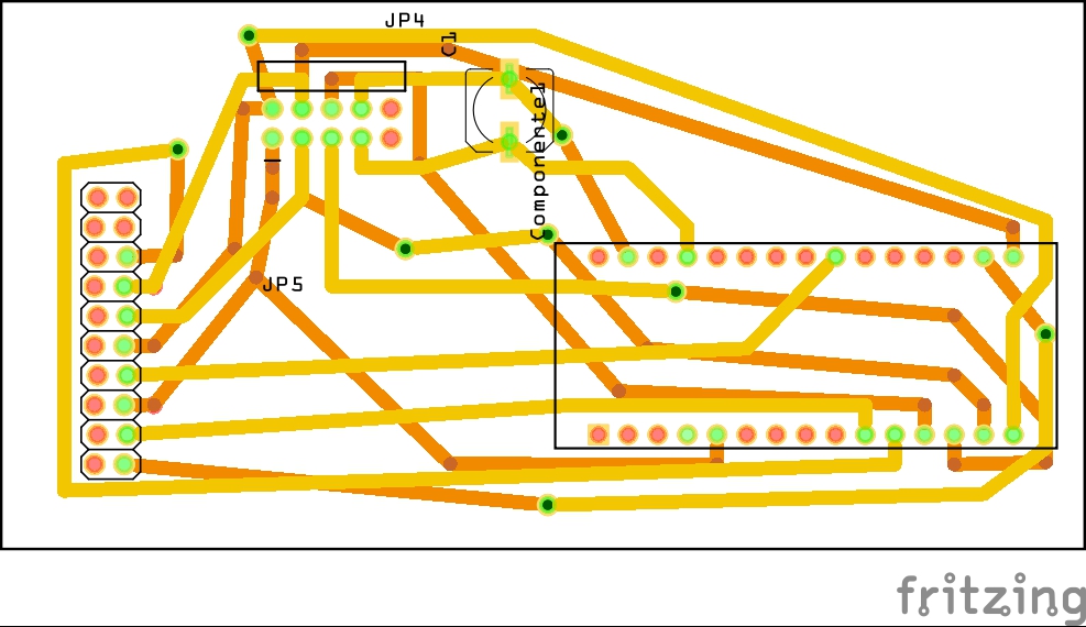
RFID-RC522 problem connecting via RJ45 cablehello everyone, I have created a two modules with 3d printer, I followed another project created by Barte, to open the garage, but I've used it, to turn to disable alarm inside the house, of course I made some changes the original design. Now I finished and running the project, I mounted the RFID-rc522 form and i connected to another module where inside there is Arduino and radio. I connected via RJ45 cable and the distance of 3 meters. The radio module is no longer recognized. my question is spontaneous at this point. How can I fix the problem?
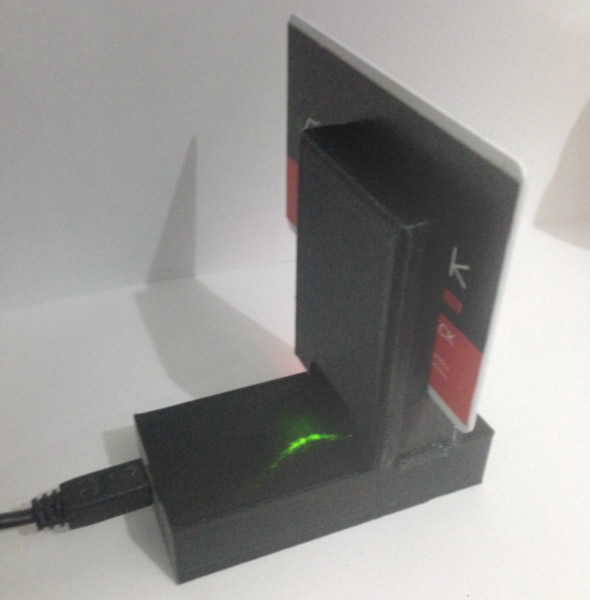


Attention to the fourth pin from the bottom not connected to rc522 form because that cable I used for the LED and therefore not connected to rc522

-
RFID Garage door openerhello to all guys, I noticed some problems, if the power goes away there is a flaw in the system. I modified the source as needed to me, now you turn the sensor on domoticz when you turn on and off when you turn off. I modified the project to create an alarm homemade I configured via lua script the motion sensors. I mounted on the bell so as to turn on and off when I go out or within the home. thank you all
-
New nRF24 driver in MySensors 2.0.0@tekka wow
-
problem to code? -
problem to code?the problem was the radio module nrf24, replacing it I solved
ps
when you see lots of nrf24 not buy them on the cheap. thank you all for the support -
2 SWITCH 2 RELAY -
problem to code? -
problem to code?#include <MySigningNone.h> #include <MyTransportNRF24.h> //#include <MyTransportRFM69.h> #include <MyHwATMega328.h> #include <MySensor.h> #include <SPI.h> #include "Bounce2.h" //char sketch_name[] = "Multy-Relay"; //char sketch_ver[] = "0.1"; #define RELAY_ON 0 // switch around for realy HIGH/LOW state #define RELAY_OFF 1 #define DEBUG On // MySensor gw; #define RADIO_ID 45 // radio Id, whatever channel you assigned to #define noRelays 2 const int relayPin[] = {3,4}; // switch around pins to your desire const int buttonPin[] = {6,7}; // switch around pins to your desire class Relay // relay class, store all relevant data (equivalent to struct) { public: int buttonPin; // physical pin number of button int relayPin; // physical pin number of relay byte oldValue; // last Values for key (debounce) boolean relayState; // relay status (also stored in EEPROM) }; Relay Relays[noRelays]; Bounce debouncer[noRelays]; MyMessage msg[noRelays]; void setup() { gw.begin(incomingMessage, RADIO_ID, true); delay(500); gw.sendSketchInfo("Bar-Multy-Relay&Interruttori", "0.4"); delay(500); // Initialize Relays with corresponding buttons for (int i = 0; i < noRelays; i++) { Relays[i].buttonPin = buttonPin[i]; // assign physical pins Relays[i].relayPin = relayPin[i]; msg[i].sensor = i; // initialize messages msg[i].type = V_LIGHT; debouncer[i] = Bounce(); // initialize debouncer debouncer[i].attach(buttonPin[i]); debouncer[i].interval(5); pinMode(Relays[i].buttonPin, INPUT_PULLUP); pinMode(Relays[i].relayPin, OUTPUT); Relays[i].relayState = gw.loadState(i); // retrieve last values from EEPROM digitalWrite(Relays[i].relayPin, Relays[i].relayState ? RELAY_ON : RELAY_OFF); // and set relays accordingly gw.send(msg[i].set(Relays[i].relayState ? true : false)); // make controller aware of last status gw.present(i, V_LIGHT); // present sensor to gateway delay(250); } } void loop() { gw.process(); for (byte i = 0; i < noRelays; i++) { debouncer[i].update(); byte value = debouncer[i].read(); //if (value != Relays[i].oldValue && value == 0) if (value != Relays[i].oldValue) { Relays[i].relayState = !Relays[i].relayState; gw.send(msg[i].set(Relays[i].relayState ? true : false)); digitalWrite(Relays[i].relayPin, Relays[i].relayState ? RELAY_ON : RELAY_OFF); gw.saveState( i, Relays[i].relayState ); } // save sensor state in EEPROM (location == sensor number) Relays[i].oldValue = value; } } // process incoming message void incomingMessage(const MyMessage &message) { if (message.type == V_LIGHT) { if (message.sensor < noRelays) // check if message is valid for relays..... previous line [[[ if (message.sensor <=noRelays){ ]]] { Relays[message.sensor].relayState = message.getBool(); digitalWrite(Relays[message.sensor].relayPin, Relays[message.sensor].relayState ? RELAY_ON : RELAY_OFF); // and set relays accordingly gw.saveState( message.sensor, Relays[message.sensor].relayState ); // save sensor state in EEPROM (location == sensor number) } } }REport
send: 44-44-0-0 s=255,c=3,t=15,pt=2,l=2,sg=0,st=fail:0
send: 44-44-0-0 s=255,c=0,t=18,pt=0,l=5,sg=0,st=fail:1.5.4
send: 44-44-0-0 s=255,c=3,t=6,pt=1,l=1,sg=0,st=fail:0
repeater started, id=44, parent=0, distance=0
send: 44-44-0-0 s=255,c=3,t=11,pt=0,l=25,sg=0,st=fail:Bar-Multy-Relay&Interrutt
send: 44-44-0-0 s=255,c=3,t=12,pt=0,l=3,sg=0,st=fail:0.4
send: 44-44-0-0 s=0,c=1,t=2,pt=2,l=2,sg=0,st=fail:0
find parent
send: 44-44-255-255 s=255,c=3,t=7,pt=0,l=0,sg=0,st=bc:
send: 44-44-0-0 s=0,c=0,t=2,pt=0,l=0,sg=0,st=fail:
send: 44-44-0-0 s=1,c=1,t=2,pt=2,l=2,sg=0,st=fail:0
send: 44-44-0-0 s=1,c=0,t=2,pt=0,l=0,sg=0,st=fail:
send: 44-44-0-0 s=0,c=1,t=2,pt=2,l=2,sg=0,st=fail:1
send: 44-44-0-0 s=1,c=1,t=2,pt=2,l=2,sg=0,st=fail:1

<<< reset button

send: 44-44-0-0 s=255,c=3,t=15,pt=2,l=2,sg=0,st=fail:0
send: 44-44-0-0 s=255,c=0,t=18,pt=0,l=5,sg=0,st=fail:1.5.4
send: 44-44-0-0 s=255,c=3,t=6,pt=1,l=1,sg=0,st=fail:0
repeater started, id=44, parent=0, distance=0
send: 44-44-0-0 s=255,c=3,t=11,pt=0,l=25,sg=0,st=fail:Bar-Multy-Relay&Interrutt
send: 44-44-0-0 s=255,c=3,t=12,pt=0,l=3,sg=0,st=fail:0.4
send: 44-44-0-0 s=0,c=1,t=2,pt=2,l=2,sg=0,st=fail:1
find parent
send: 44-44-255-255 s=255,c=3,t=7,pt=0,l=0,sg=0,st=bc:
send: 44-44-0-0 s=0,c=0,t=2,pt=0,l=0,sg=0,st=fail:
send: 44-44-0-0 s=1,c=1,t=2,pt=2,l=2,sg=0,st=fail:1
send: 44-44-0-0 s=1,c=0,t=2,pt=0,l=0,sg=0,st=fail:
send: 44-44-0-0 s=0,c=1,t=2,pt=2,l=2,sg=0,st=fail:0
send: 44-44-0-0 s=1,c=1,t=2,pt=2,l=2,sg=0,st=fail:0
:triumph:
-
2 SWITCH 2 RELAY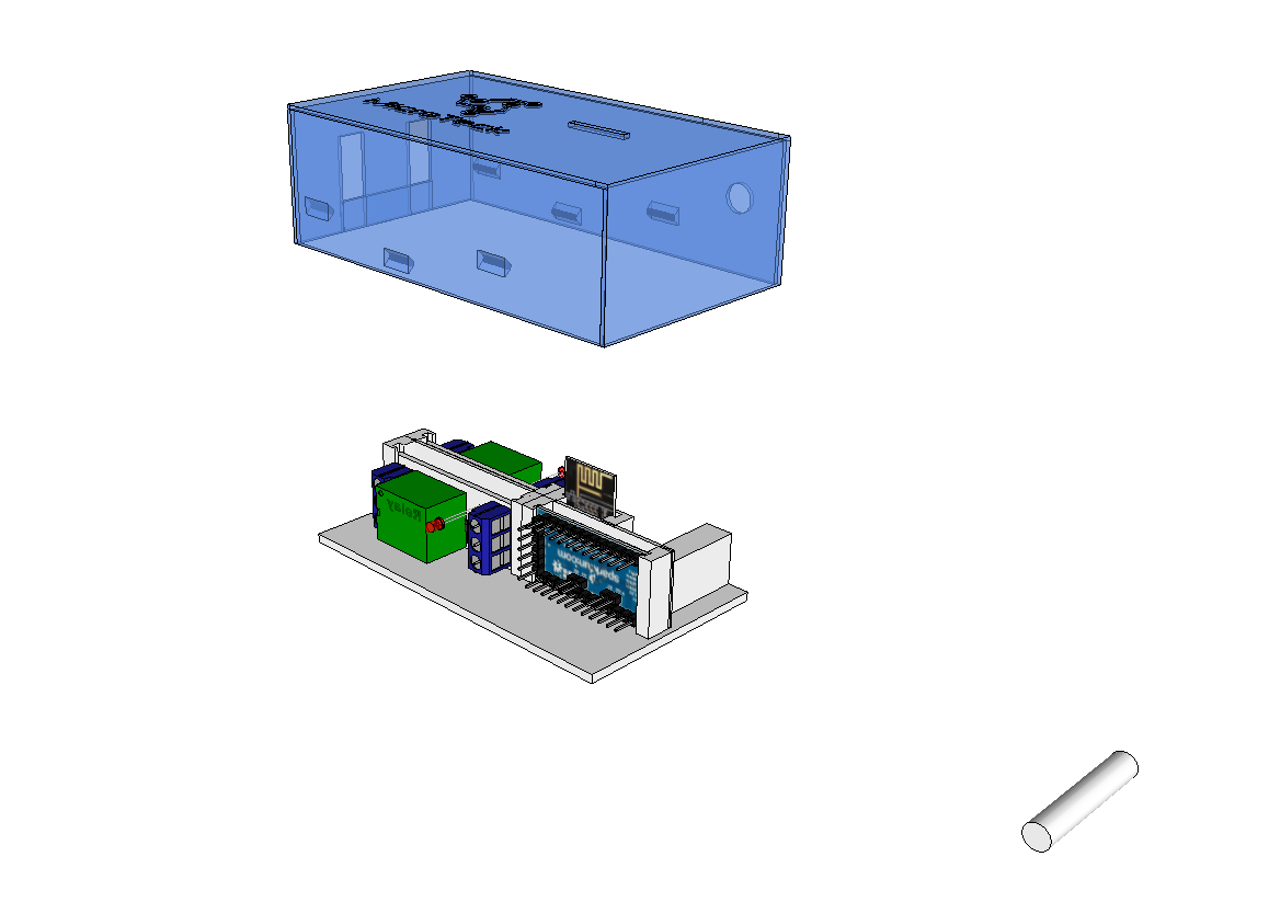
File 3d print
0_1461521471055_PROGETTO_base.stl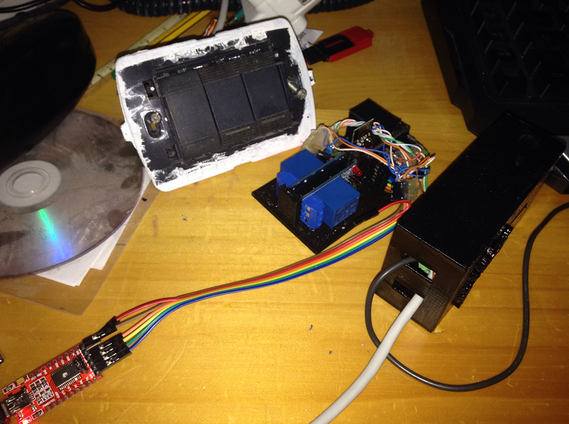
I need help on the codePin 3/4 Relay

Pin 6/7 Switches

https://codebender.cc/sketch:291491
BinarySwitch Sensor Example, we agree to aid in the development of the code.
work in progress. -
Relay_Actuator add second relay?solution vera

