💬 Motion Sensor


  • Admin

    This thread contains comments for the article "Motion Sensor" posted on MySensors.org.


  • step-up regulator is not needed for 3V the easiest way is removing stabilizer an diode and replace by wire. HC-SR01 sensor inner works with 3 to 5V


  • I have just started with an Arduino Nano and connected both radio and a HC-SR50I PIR.
    When I check the Serial monitor it spams me with
    0;1;1;0;16;0

    Is that common or is something wrong? Thanks for help.


  • @Patrik Söderström I think this is normal. Please check the Serial Protocol spec. under Download & API above to understand what the different elements describe. You should get this message once every two minutes if SLEEP_TIME = 120000 and you do not trigger the PIR. If triggered you should get 0;1;1;0;16;1 followed by 0;1;1;0;16;0 when the PIR resets. I built the Motion detector using the MiniPIR module above but I found that it needs at least +5V to operate reliably. Below 5V I think I remember that I got a lot of false trigs.


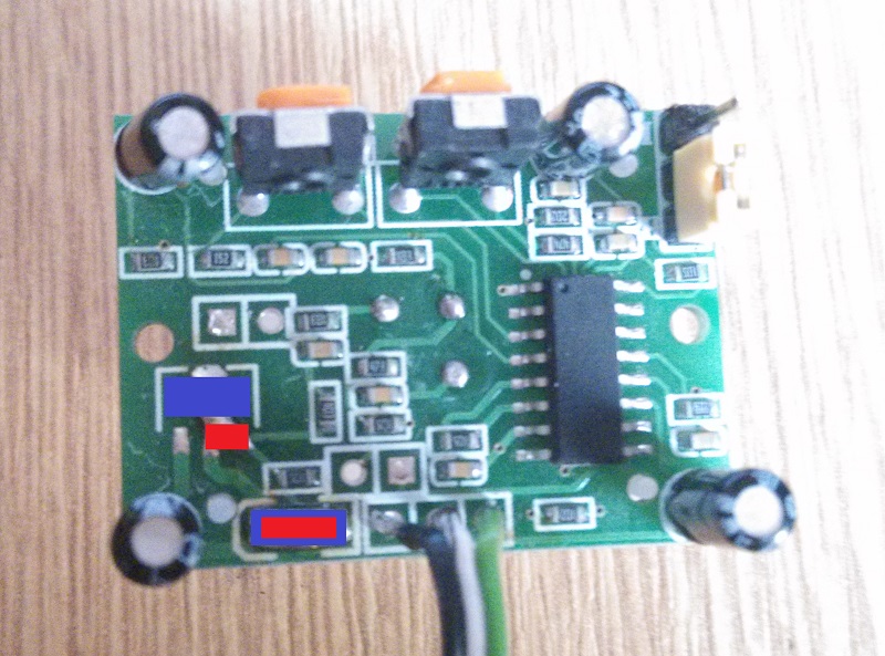
  • @xlibor Where these? Stabilizer and diode what needed replace with wire.


  • Blue - parts to be removed
    Red - wire or tin short circuit
    0_1476112640045_IMG_20161010_120006.jpg


  • Thank you. I try.


  • Is it possible to break both interrupt pins on a board? cus with or without a pir, the serial monitor keeps getting spammed.


  • Hi to everyone,
    it's possible to connect more than one PIR Sensor to the same board ?
    In case if it's possible, there's a limit on that number ?

    Thank you for your help


  • Mod

    @Mercury69 do you want to know which pir fired, or just combine them all?


  • @Yveaux
    Hi Yveaux, I want to know if it's possible to connect more than one PIR sensor at the same node and if there's a limit on the number.

    I mean the possibility to have only 1 node with connected more PIR sensor in order to avoid the moltiplication of the assembly composed by arduino+radio+PIR+power supply.

    I imagine (but I'm not sure) if I connect more PIR sensor to the same PIN3 on arduino node I will obtain a "network" of PIR Sensor reacting as a single element to a possible presence, without the possibility to differentiate the area interested by the alarm.

    If I can differentiate the PIN where I can connect the PIR sensor, maybe I can get information from each single area of detection controlled by the PIR sensor.

    Thank you for your attention.


  • @Mercury69 PIR is based on interrupts, which wake-up processor from sleep mode, Arduinos based on ATMEGA328 have only two these pins, pin 2 and 3.

    You can use 2 PIRs with detection which was fired, if you need more than two PIRs you can connect each PIR to any digital input of arduino and common signal OR-ing from all PIRs to generate interrupt to pin 2 or 3. Then if you wake-up by interrupt you can software test all of digital inputs and resolve which PIR was fired.


  • Mod

    @xlibor said:

    ANDed

    Better ORed, or all your sensors have to trigger at the same time to wake up the Arduino 😉

    For the rest @xlibor is right: OR-ing PIR triggers into a single wake-up signal can be as simple as using a diode per PIR and a resistor:
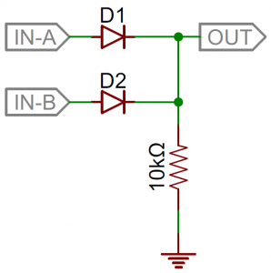
    alt text

    Ref: https://learn.sparkfun.com/tutorials/diodes/diode-applications


  • Do you have an example sketch of connecting two PIRs to one Arduino? Would really need that in my setup.


  • @Patrik-Söderström said:

    Do you have an example sketch of connecting two PIRs to one Arduino? Would really need that in my setup.

    And so do I. Have tried to accomplish this as my first mysensors project, but coming up short... 😞


  • Hi all

    I have build a node with this setup.
    It is an Arduino Pro Mini with a SR501 and a RFL01. Arduino and sensor converted to 3.3V.
    Motion is detected like it should, no trouble.

    But everytime my arduino hits this :

       // Sleep until interrupt comes in on motion sensor. Send update every two minute.
        sleep(digitalPinToInterrupt(DIGITAL_INPUT_SENSOR), CHANGE, SLEEP_TIME);
    

    the node returns a "high"... meaning there's motion (where there is not actually)
    So my notification board gets a new entry every two minutes...

    Is this normal beahaviour ? (Hope not!!! 😉 )


  • Hi ben999
    I don't know what your sketch looks like but in my implementation I catch the movement in a boolean variable called tripped which I use to set the message sent to the controller.

    // Read digital motion value
    boolean tripped = digitalRead(DIGITAL_INPUT_SENSOR) == HIGH; 
    send(msgm.set(tripped?"1":"0"));  // Send tripped value to gw
    

    Then I do some other stuff based on tripped being true or false.
    Before the node goes to sleep I reset tripped. Otherwise I will get the old value back next time the node wakes up after SLEEP_TIME regardless if there is movement or not.

    // Sleep until interrupt comes in on motion sensor but send update every minute. 
      tripped = false;  //reset tripped
      sleep(INTERRUPT,CHANGE, SLEEP_TIME);
    

    It goes without saying that SLEEP_TIME will have to be longer than the reset time of the sensor itself. My sensor element resets in about 20 seconds, which puts a lower limit to SLEEP_TIME.


  • So my notification board gets a new entry every two minutes...

    The SLEEP_TIME define tells your board to wake up every two minutes regardless of whether there is an interrupt. If you want longer, increase this value. I think you can also set it to 0 to only wake on interrupts.


  • @bgunnarb
    Thank you very much for your message
    I added tripped = false; to my sketch but that didn't change the general behaviour : sensor still give false trigger when coming out of sleep period...

    @Graham
    Thank you very much for your message as well

    I might not have described my problem precisely enough :
    Motion sensor will be used as part of an house alarm
    I have set up a very simple rule for now (home.rules) stating that

    when sensor changed from CLOSED to OPEN
       then sendBroadcastNotification(to me)
    

    This works fine and node comes out of sleep when motion triggers the interrupt. All fine.

    Trouble is when we get to the end of the sleeptime... node comes out of sleep and i get a "tripped" that sends me a notification (or later on will set the siren on!!!)

    @Graham 's idea is pretty good: keep node asleep forever until interrupt kicks in...
    But nodes do have temperature, humidity and battery statuses to share...

    I tried to load the basic sketch (ignoring temp, hum and batt) but node still behaves the same... 😞

    Does it not do the same at yours ?

    #define MY_RADIO_NRF24
    
    #include <MySensors.h>
    
    unsigned long SLEEP_TIME = 120000; 
    #define DIGITAL_INPUT_SENSOR 3
    #define CHILD_ID 1
    
    MyMessage msg(CHILD_ID, V_TRIPPED);
    
    void setup()
    {
        pinMode(DIGITAL_INPUT_SENSOR, INPUT); 
    }
    
    void presentation()
    {
        sendSketchInfo("Motion Sensor", "1.0");
        present(CHILD_ID, S_MOTION);
    }
    
    void loop()
    {
        bool tripped = digitalRead(DIGITAL_INPUT_SENSOR) == HIGH;
        send(msg.set(tripped?"1":"0")); 
        sleep(digitalPinToInterrupt(DIGITAL_INPUT_SENSOR), CHANGE, SLEEP_TIME);
    }
    

    Thanks a lot for your help


  • @ben999 The sketch you have will report the state of the pin every 2 minutes as well as when interrupted by motion.

    If the SR501 is still within its timeout after the last motion detected, the pin will still be high. Eventually, (the maximum length of time is about 10 minutes) the pin should go low. If it doesn't, there is a fault with the SR501.

    The timeout can be adjusted by one of the dials (see http://henrysbench.capnfatz.com/henrys-bench/arduino-sensors-and-input/arduino-hc-sr501-motion-sensor-tutorial/#Time_Delay_Adjustment). I'm not sure what the shortest period is, but it is probably less than two minutes, which would send 0 in the next message.

    You would, however, get another interrupt if more motion occurred before the two minutes are up.


  • @Graham Thank you for your reply

    SR501 seem to work fine on two fronts:

    • the arduino IDE serial monitor shows the SR501 going ON then OFF after 5s (as per dial)
    • same serial monitor shows that sensor gets motion when it occurs...

    I'll have a go with another node just to be sure

    Thanks again for your help (both of you 🙂 )


  • If I wanted to add two PIRs to one sensor-node would this sketch work?

    /**
     * The MySensors Arduino library handles the wireless radio link and protocol
     * between your home built sensors/actuators and HA controller of choice.
     * The sensors forms a self healing radio network with optional repeaters. Each
     * repeater and gateway builds a routing tables in EEPROM which keeps track of the
     * network topology allowing messages to be routed to nodes.
     *
     * Created by Henrik Ekblad <henrik.ekblad@mysensors.org>
     * Copyright (C) 2013-2015 Sensnology AB
     * Full contributor list: https://github.com/mysensors/Arduino/graphs/contributors
     *
     * Documentation: http://www.mysensors.org
     * Support Forum: http://forum.mysensors.org
     *
     * This program is free software; you can redistribute it and/or
     * modify it under the terms of the GNU General Public License
     * version 2 as published by the Free Software Foundation.
     *
     *******************************
     *
     * REVISION HISTORY
     * Version 1.0 - Henrik Ekblad
     *
     * DESCRIPTION
     * Motion Sensor example using HC-SR501
     * http://www.mysensors.org/build/motion
     *
     */
    
    // Enable debug prints
    // #define MY_DEBUG
    
    // Enable and select radio type attached
    #define MY_RADIO_NRF24
    //#define MY_RADIO_RFM69
    
    #include <MySensors.h>
    
    unsigned long SLEEP_TIME = 120000; // Sleep time between reports (in milliseconds)
    #define DIGITAL_INPUT_SENSOR_1 2
    #define DIGITAL_INPUT_SENSOR_2 3  // The digital input you attached your motion sensor.  (Only 2 and 3 generates interrupt!)
    #define CHILD_ID_1 1   // Id of the sensor child
    #define CHILD_ID_2 2   // Id of the sensor child
    
    // Initialize motion message
    MyMessage msg(CHILD_ID_1, V_TRIPPED);
    
    
    void setup()
    {
        pinMode(DIGITAL_INPUT_SENSOR_1, INPUT);      // sets the motion sensor digital pin as input
        pinMode(DIGITAL_INPUT_SENSOR_2, INPUT);      // sets the motion sensor digital pin as input
    }
    
    void presentation()
    {
        // Send the sketch version information to the gateway and Controller
        sendSketchInfo("Motion Sensor_Dual", "1.0");
    
        // Register all sensors to gw (they will be created as child devices)
        present(CHILD_ID_1, S_MOTION);
        present(CHILD_ID_2, S_MOTION);
    }
    
    void loop()
    {
        // Read digital motion value
        bool tripped_1 = digitalRead(DIGITAL_INPUT_SENSOR_1) == HIGH;
        bool tripped_2 = digitalRead(DIGITAL_INPUT_SENSOR_2) == HIGH;
    
        Serial.println(tripped_1 || tripped_2);
        if(tripped_1){
        send(msg.set(tripped_1?"1":"0"));  // Send tripped value to gw
        }
        if(tripped_2){
        send(msg.set(tripped_2?"1":"0"));  // Send tripped value to gw
        }
        // Sleep until interrupt comes in on motion sensor. Send update every two minute.
        sleep(digitalPinToInterrupt(DIGITAL_INPUT_SENSOR_1 || DIGITAL_INPUT_SENSOR_1), CHANGE, SLEEP_TIME);
    }
    

    I know PIN 2 is supposed to be connected to the radio but I read somewhere that it is not used.


  • @ben999 Did you get your sensor sorted? I have the same issue with the sensor reporting tripped after going out of sleep, same goes for wait. Putting the exact same logic in a sketch without MYS and I have no issues... going crazy soon


  • Does anyone know why my sensor only reacts when I move my hand just in front of it. From a distance it does not work. Has tested with different HC-SR501 PIR and adjusted also and various radio but all gave the same result.

    /**
     * The MySensors Arduino library handles the wireless radio link and protocol
     * between your home built sensors/actuators and HA controller of choice.
     * The sensors forms a self healing radio network with optional repeaters. Each
     * repeater and gateway builds a routing tables in EEPROM which keeps track of the
     * network topology allowing messages to be routed to nodes.
     *
     * Created by Henrik Ekblad <henrik.ekblad@mysensors.org>
     * Copyright (C) 2013-2015 Sensnology AB
     * Full contributor list: https://github.com/mysensors/Arduino/graphs/contributors
     *
     * Documentation: http://www.mysensors.org
     * Support Forum: http://forum.mysensors.org
     *
     * This program is free software; you can redistribute it and/or
     * modify it under the terms of the GNU General Public License
     * version 2 as published by the Free Software Foundation.
     *
     *******************************
     *
     * REVISION HISTORY
     * Version 1.0 - Henrik Ekblad
     * 
     * DESCRIPTION
     * Motion Sensor example using HC-SR501 
     * http://www.mysensors.org/build/motion
     *
     */
    
    // Enable debug prints
    // #define MY_DEBUG
    
    // Enable and select radio type attached
    #define MY_RADIO_NRF24
    //#define MY_RADIO_RFM69
    
    #include <SPI.h>
    #include <MySensors.h>
    
    unsigned long SLEEP_TIME = 120000; // Sleep time between reports (in milliseconds)
    #define DIGITAL_INPUT_SENSOR 3   // The digital input you attached your motion sensor.  (Only 2 and 3 generates interrupt!)
    #define CHILD_ID 1   // Id of the sensor child
    
    // Initialize motion message
    MyMessage msg(CHILD_ID, V_TRIPPED);
    
    void setup()  
    {  
      pinMode(DIGITAL_INPUT_SENSOR, INPUT);      // sets the motion sensor digital pin as input
    }
    
    void presentation()  {
      // Send the sketch version information to the gateway and Controller
      sendSketchInfo("Motion Sensor", "1.0");
    
      // Register all sensors to gw (they will be created as child devices)
      present(CHILD_ID, S_MOTION);
    }
    
    void loop()     
    {     
      // Read digital motion value
      boolean tripped = digitalRead(DIGITAL_INPUT_SENSOR) == HIGH; 
            
      Serial.println(tripped);
      send(msg.set(tripped?"1":"0"));  // Send tripped value to gw 
    
      // Sleep until interrupt comes in on motion sensor. Send update every two minute.
      sleep(digitalPinToInterrupt(DIGITAL_INPUT_SENSOR), CHANGE, SLEEP_TIME);
    }


  • Mod

    @miro
    have you tried to power he sensor with external 5v instead of 5v pin from arduino?


  • Hi all,

    The motion sensor project is my first using Arduino and MySensors! I've managed to get the Gateway all up and running and the motion sensor to communicate with it (using the standard ino file from the project page), but I seem to have a couple of issues:

    • Despite the default sleep time it seems to be communicating with the Gateway constantly.
    • Permanently displayed as in an 'On' state in Domoticz.

    I've tried adjusting the sensitivity and time but it doesn't seem to make a difference.

    I don't know which bit is supposed to contain the values which I can decipher with the serial protocol guide so apologies if the answer is staring me in the face!

    Gateway received
    0;255;3;0;9;TSF:MSG:READ,1-1-0,s=1,c=1,t=16,pt=0,l=1,sg=0:1
    1;1;1;0;16;1

    Node sent
    0
    1383086 TSF:MSG:SEND,1-1-0-0,s=1,c=1,t=16,pt=0,l=1,sg=0,ft=0,st=OK:0
    1383106 MCO:SLP:MS=120000,SMS=0,I1=1,M1=1,I2=255,M2=255
    1383120 MCO:SLP:TPD
    1383127 MCO:SLP:WUP=1

    Any help would be appreciated 🙂


  • Mod

    try to use a 10uF or bigger capacitor on the 5v and GND, I had issues with mine triggering randomly and after using a stable 5v supply it got back to normal: in fact later on when I added the capacitor to help the NRF24 radio it also stabilized the 5V for the sensor and it is now working fine.
    Did you try to use just a sleep(2000) without the interrupt? Just to check if it is going to sleep correctly


  • Hi,

    i'm trying to get my motionsensor working, but i see only 0 in the terminal what send to the gateway. Does anyone know why i only see that 0 and not a 1? I'm asuming that 1 is a movement.


  • I have found in my experiments with the PIR motion sensor that at least the type that I am using is extremely sensitive to ripple in the Vcc voltage.

    First of all, it is unstable as the feed voltage approaches 5V and then it triggers spontaneously again and again. I then tried to rise the voltage to around 11V which is the voltage that the battery eliminator gives. But that voltage has a ripple of 0.1 volt amplitude so this triggers the sensor again and again also since the arduino introduces small changes in the voltage when it processes the script.

    The solution was to install a LM317 voltage regulator to bring down the voltage to 8V which is then ripple free and stable. Now the PIR works very well and does not give false triggers.

    The arduino is fed from a separate voltage regulator giving 5V. I tried to connect the battery eliminator directly to RAW but that released the smoke from the on-board voltage regulator and as you know, when you let the smoke out from components, they no longer work. 😀

    Apparently the battery eliminator also produces some voltage spikes that are not healthy.


  • Mod

    I solved my random pir triggers with a Capacitor on the 5v pin.


  • @Kieren-Perry said in 💬 Motion Sensor:

    Hi all,

    The motion sensor project is my first using Arduino and MySensors! I've managed to get the Gateway all up and running and the motion sensor to communicate with it (using the standard ino file from the project page), but I seem to have a couple of issues:

    • Despite the default sleep time it seems to be communicating with the Gateway constantly.
    • Permanently displayed as in an 'On' state in Domoticz.

    I've tried adjusting the sensitivity and time but it doesn't seem to make a difference.

    I don't know which bit is supposed to contain the values which I can decipher with the serial protocol guide so apologies if the answer is staring me in the face!

    Gateway received
    0;255;3;0;9;TSF:MSG:READ,1-1-0,s=1,c=1,t=16,pt=0,l=1,sg=0:1
    1;1;1;0;16;1

    Node sent
    0
    1383086 TSF:MSG:SEND,1-1-0-0,s=1,c=1,t=16,pt=0,l=1,sg=0,ft=0,st=OK:0
    1383106 MCO:SLP:MS=120000,SMS=0,I1=1,M1=1,I2=255,M2=255
    1383120 MCO:SLP:TPD
    1383127 MCO:SLP:WUP=1

    Any help would be appreciated 🙂

    Thanks for all your comments! Tried the capacitor route but no dice. In the end, connected a 9v battery to the jack and the PIR to the VIN as the voltage from the 5v pin and USB was a little below what it should have been.


  • If I want something to run for 10 seconds after a motion have been detected, how would I make this happend?


  • Mod

    Set a timer in the code, that's shouldn't be very hard to do.


  • I have never used timers but I looked at the blink without delay sketch from the arduino website. Do I replace the if -statement with a while loop?

    const int ledPin =  LED_BUILTIN;// the number of the LED pin
    
    // Variables will change :
    int ledState = LOW;             // ledState used to set the LED
    
    // Generally, you should use "unsigned long" for variables that hold time
    // The value will quickly become too large for an int to store
    unsigned long previousMillis = 0;        // will store last time LED was updated
    
    // constants won't change :
    const long interval = 1000;           // interval at which to blink (milliseconds)
    
    void setup() {
      // set the digital pin as output:
      pinMode(ledPin, OUTPUT);
    }
    
    void loop() {
      // here is where you'd put code that needs to be running all the time.
    
      // check to see if it's time to blink the LED; that is, if the
      // difference between the current time and last time you blinked
      // the LED is bigger than the interval at which you want to
      // blink the LED.
      unsigned long currentMillis = millis();
    
      if (currentMillis - previousMillis >= interval) {
        // save the last time you blinked the LED
        previousMillis = currentMillis;
    
        // if the LED is off turn it on and vice-versa:
        if (ledState == LOW) {
          ledState = HIGH;
        } else {
          ledState = LOW;
        }
    
        // set the LED with the ledState of the variable:
        digitalWrite(ledPin, ledState);
      }
    }
    

  • Mod

    Just leave it as it is, just put a condition that will trigger the if statement only once the pir sensor got triggered


  • Hardware Contributor

    I would actually not do this in a node but in the controller (at least if I get what you are trying to do right). I have done that with some scripting in domoticz. I have lights that that are switched on for 5 minutes when motion is detected and shut down 5 minutes after the last motion stopped. Motion sensor and rgbw controller are different mysensor nodes. Much more versatile then hardcoding this in you node's code.


  • @LastSamurai
    Would you do that through "rules" ?


  • Mod

    @ben999 yes.

    @LastSamurai I know that hardcoding is less flexible, but at least it can work even if controller is down or disconnected, of course it depends how critical is the actuator.


  • So, I notice that the HC-SR501 has a 7133-1 voltage regulator on-board which I guess means that the logic is actually driven with 3.3V and not 5V.

    Is it possible to bypass the regulator and power the sensor directly with the 3.3V I am using to power my nano with?


  • @maghac Aha, guess I should read old posts first 🙂


  • Mod

    Just make sure the power source is stable otherwise you will end up with random triggers from pir sensor


  • @gohan @maghac

    From my little experience : when running from 2 AA batteries with sketch as it is I got random triggers continuousely

    Adding a delay() before entering sleep() sorted things out (something like 3 sec is necessary to get power stable again)

    Not sure it's the smartest way of doing it, but it works...

    Any comment on the security side of it? Could my node miss some action during these 3 sec ? Or the interrupt pin would still listen to the PIR sensor pin ?


  • Mod

    I think it will miss the pir trigger


  • @gohan

    Thank you for your reply

    Could you please explain a bit further ?

    Interrupt pin would still read the trigger during delay()?
    Data would be lost as the sketch is frozen during delay() ?
    Or data is saved in some buffer, ready to be used as soon as sketch comes back to life ?

    My view is that it shouldn't matter too much if i miss a trigger after a trigger : the first trigger will wake my node and transmit to gateway. So job done. Alarm goes off.

    On the other hand, I guess a millis() would be neater ?

    Thanks a lot for your input


  • Mod

    I am saying that during delay no code is executed and interrupt only attaches to pin when executing the sleep function, so if motion if triggered during the delay it will not be detected by interrupt; maybe it could detect the CHANGE when pir goes from high to low but it will then report "no motion" and it will not trigger alarm if it set to go off on "motion" only.


  • @gohan

    Thanks a lot

    Got it now

    delay() to be avoided then !

    I will have a look at millis() instead


  • Mod

    Delay is not bad, depends how you use it. Maybe you could use an if statement to check pin state is low before entering sleep


  • Millis won't work with the SLEEP funtion either. REcently added to the API....


  • Hi, I´ve read this above

    "however this sensor requires 5 VDC so you will need to use a step-up regulator if you are running the 3.3V version of the Arduino Pro Mini."

    So I am using 3 V, could you propose a fitting step up regulator so I can use this PIR (best from ebay)? Thank you!


  • @siod said in 💬 Motion Sensor:

    a

    You have a HC-SR501 sensor? I had that same question before and then I realized that the HC-SR501 actually has a 3.3 V regulator and if you bypass it you can run it on 3.3V.


  • @Cliff-Karlsson
    For dual Sensors

    one error is present on the line sleep:
    it is not : sleep(digitalPinToInterrupt(DIGITAL_INPUT_SENSOR_1 || DIGITAL_INPUT_SENSOR_1), CHANGE, SLEEP_TIME);

    but : sleep(digitalPinToInterrupt(DIGITAL_INPUT_SENSOR_1 )|| digitalPinToInterrupt(DIGITAL_INPUT_SENSOR_2), CHANGE, SLEEP_TIME);


  • hi,
    i want to ad a motion sensor to my project (3 dimmers on a arduino uno using nrf24).
    My first problem is that the 2 and 3 pins are not available (nrf24 and pwm dimmer), so i will take the pin 1 for testing
    second is the sleeping time during i can't send any light message to my dimmers...


  • this is my code

    /**
     * The MySensors Arduino library handles the wireless radio link and protocol
     * between your home built sensors/actuators and HA controller of choice.
     * The sensors forms a self healing radio network with optional repeaters. Each
     * repeater and gateway builds a routing tables in EEPROM which keeps track of the
     * network topology allowing messages to be routed to nodes.
     *
     * Created by Henrik Ekblad <henrik.ekblad@mysensors.org>
     * Copyright (C) 2013-2015 Sensnology AB
     * Full contributor list: https://github.com/mysensors/Arduino/graphs/contributors
     *
     * Documentation: http://www.mysensors.org
     * Support Forum: http://forum.mysensors.org
     *
     * This program is free software; you can redistribute it and/or
     * modify it under the terms of the GNU General Public License
     * version 2 as published by the Free Software Foundation.
     *
     *******************************
     *
     * REVISION HISTORY
     * Version 1.0 - February 15, 2014 - Bruce Lacey
     * Version 1.1 - August 13, 2014 - Converted to 1.4 (hek)
     *
     * DESCRIPTION
     * This sketch provides a Dimmable LED Light using PWM and based Henrik Ekblad
     * <henrik.ekblad@gmail.com> Vera Arduino Sensor project.
     * Developed by Bruce Lacey, inspired by Hek's MySensor's example sketches.
     *
     * The circuit uses a MOSFET for Pulse-Wave-Modulation to dim the attached LED or LED strip.
     * The MOSFET Gate pin is connected to Arduino pin 3 (LED_PIN), the MOSFET Drain pin is connected
     * to the LED negative terminal and the MOSFET Source pin is connected to ground.
     *
     * This sketch is extensible to support more than one MOSFET/PWM dimmer per circuit.
     * http://www.mysensors.org/build/dimmer
     * 
     * 
     * LISTE DE POINTS:
     * D0  DISPO
     * D1  MOTION
     * D2  IRQ NRF
     * D3  LED1
     * D4  DISPO
     * D5  LED2
     * D6  LED3
     * D7  DISPO
     * D8  DISPO
     * D9  CE NRF
     * D10 CSN/CS NRF
     * D11 MOSI NRF
     * D12 MISO NRF
     * D13 SCK NRF
     * D14 DISPO
     * 
     * 
     */
    
    // Enable debug prints to serial monitor
    #define MY_DEBUG 
    
    // Enable and select radio type attached
    #define MY_RADIO_NRF24
    //#define MY_RADIO_RFM69
    
    //#define MY_NODE_ID 153 
    
    #include <SPI.h>
    #include <MySensors.h> 
    
    #define SN "BUREAU PARENTS"
    #define SV "1.2"
    
    #define noLEDs 3
    const int LED_Pin[] = {3, 5, 6}; 
    
    #define FADE_DELAY 10  // Delay in ms for each percentage fade up/down (10ms = 1s full-range dim)
    
    static int currentLevel1 = 0;  // Current dim level...
    static int currentLevel2 = 0;  // Current dim level...
    static int currentLevel3 = 0;  // Current dim level...
    
    MyMessage dimmer1Msg(1, V_DIMMER);
    MyMessage light1Msg(1, V_LIGHT);
    MyMessage dimmer2Msg(2, V_DIMMER);
    MyMessage light2Msg(2, V_LIGHT);
    MyMessage dimmer3Msg(3, V_DIMMER);
    MyMessage light3Msg(3, V_LIGHT);
    
    // MOTION SENSOR
    uint32_t SLEEP_TIME = 120000; // Sleep time between reports (in milliseconds)
    #define DIGITAL_INPUT_SENSOR 1   // The digital input you attached your motion sensor.  (Only 2 and 3 generates interrupt!)
    #define CHILD_ID 4   // Id of the sensor child
    MyMessage msg(CHILD_ID, V_TRIPPED);
    
    /***
     * Dimmable LED initialization method
     */
    void setup()  
    { 
      // LEDS
      // Pull the gateway's current dim level - restore light level upon sendor node power-up
    for (int sensor=1; sensor<=noLEDs; sensor++){
      request( sensor, V_DIMMER );
     }
     // MOTION
     pinMode(DIGITAL_INPUT_SENSOR, INPUT);      // sets the motion sensor digital pin as input
    }
    
    void presentation() {
      // Register the LED Dimmable Light with the gateway
     for (int sensor=1; sensor<=noLEDs; sensor++){
     present(sensor, S_DIMMER);
     wait(2);
     }
      // MOTION
      present(CHILD_ID, S_MOTION);
      
      sendSketchInfo(SN, SV);
    }
    
    /***
     *  Dimmable LED main processing loop 
     */
    void loop() 
    {
      // Read digital motion value
        bool tripped = digitalRead(DIGITAL_INPUT_SENSOR)== HIGH;
        
        Serial.println("coucou");
        Serial.println(tripped);
        send(msg.set(tripped?"1":"0"));  // Send tripped value to gw
        }
        // Sleep until interrupt comes in on motion sensor. Send update every two minute.
        sleep(digitalPinToInterrupt(DIGITAL_INPUT_SENSOR), CHANGE, SLEEP_TIME);
    }


    void receive(const MyMessage &message) {
      if (message.type == V_LIGHT || message.type == V_DIMMER) {
    
        if (message.sensor == 1) {
    
         //  Retrieve the power or dim level from the incoming request message
        int requestedLevel1 = atoi( message.data );
        
        // Adjust incoming level if this is a V_LIGHT variable update [0 == off, 1 == on]
        requestedLevel1 *= ( message.type == V_LIGHT ? 100 : 1 );
        
        // Clip incoming level to valid range of 0 to 100
        requestedLevel1 = requestedLevel1 > 100 ? 100 : requestedLevel1;
        requestedLevel1 = requestedLevel1 < 0   ? 0   : requestedLevel1;
    
          
         fadeToLevel1( requestedLevel1, message.sensor );
        send(light1Msg.set(currentLevel1 > 0 ? 1 : 0)); 
        send(dimmer1Msg.set(currentLevel1) );}


       if (message.sensor == 2) {
       //  Retrieve the power or dim level from the incoming request message
        int requestedLevel2 = atoi( message.data );
        
        // Adjust incoming level if this is a V_LIGHT variable update [0 == off, 1 == on]
        requestedLevel2 *= ( message.type == V_LIGHT ? 100 : 1 );
        
        // Clip incoming level to valid range of 0 to 100
        requestedLevel2 = requestedLevel2 > 100 ? 100 : requestedLevel2;
        requestedLevel2 = requestedLevel2 < 0   ? 0   : requestedLevel2;
        
        fadeToLevel2( requestedLevel2, message.sensor );
        send(light2Msg.set(currentLevel2 > 0 ? 1 : 0));
        send(dimmer2Msg.set(currentLevel2) );}
         
        if (message.sensor == 3) {
       //  Retrieve the power or dim level from the incoming request message
        int requestedLevel3 = atoi( message.data );
        
        // Adjust incoming level if this is a V_LIGHT variable update [0 == off, 1 == on]
        requestedLevel3 *= ( message.type == V_LIGHT ? 100 : 1 );
        
        // Clip incoming level to valid range of 0 to 100
        requestedLevel3 = requestedLevel3 > 100 ? 100 : requestedLevel3;
        requestedLevel3 = requestedLevel3 < 0   ? 0   : requestedLevel3;
          
         fadeToLevel3( requestedLevel3, message.sensor );
        send(light3Msg.set(currentLevel3 > 0 ? 1 : 0));
        send(dimmer3Msg.set(currentLevel3) );}
        }
    
        
    }
    
    /***
     *  This method provides a graceful fade up/down effect
     */
    void fadeToLevel1( int toLevel1, int ledid1 ) {
    
      int delta1 = ( toLevel1 - currentLevel1 ) < 0 ? -1 : 1;
      
      while ( currentLevel1 != toLevel1 ) {
        currentLevel1 += delta1;
        analogWrite(LED_Pin[ledid1-1], (int)(currentLevel1 / 100. * 255) );
        wait( FADE_DELAY );
      }
    }
    void fadeToLevel2( int toLevel2, int ledid2 ) {
    
      int delta2 = ( toLevel2 - currentLevel2 ) < 0 ? -1 : 1;
      
      while ( currentLevel2 != toLevel2 ) {
        currentLevel2 += delta2;
        analogWrite(LED_Pin[ledid2-1], (int)(currentLevel2 / 100. * 255) );
        wait( FADE_DELAY );
      }
    }
    void fadeToLevel3( int toLevel3, int ledid3 ) {
    
      int delta3 = ( toLevel3 - currentLevel3 ) < 0 ? -1 : 1;
      
      while ( currentLevel3 != toLevel3 ) {
        currentLevel3 += delta3;
        analogWrite(LED_Pin[ledid3-1], (int)(currentLevel3 / 100. * 255) );
        wait( FADE_DELAY );
      }
    }
    

  • Mod

    Since it is a powered node, you don't need to put it to sleep. As for the pir you can do as you like: check pin status during loop, use an attach interrupt function on pin change, etc


  • @gohan ok thank you for answering. if i do this:

    void loop() 
    {
      // Read digital motion value
        bool tripped = digitalRead(DIGITAL_INPUT_SENSOR)== HIGH;
        
        Serial.println("coucou");
        Serial.println(tripped);
        send(msg.set(tripped?"1":"0"));  // Send tripped value to gw
        }
        // Sleep until interrupt comes in on motion sensor. Send update every two minute.
        //sleep(digitalPinToInterrupt(DIGITAL_INPUT_SENSOR), CHANGE, SLEEP_TIME);
    }
    

    the node never stop to send message to the gateway. i would like to send something only if D1 goes to high, is that possible ? (i'm starting combinating exemple and i want to understand what i do now!!)


  • @siod The HC-SR501 actually runs on 3.3VDC but has a 5VDC-3.3VDC regulator on board.

    There are several ways to bypass this regulator, but the easiest is to connect your 3.3VDC supply to pin 3 of JP3 (the one marked "H").

    You must make sure that your 3.3VDC supply is very stable, otherwise you will get false activations.

    See:
    https://randomnerdtutorials.com/modifying-cheap-pir-motion-sensor-to-work-at-3-3v/
    https://www.youtube.com/watch?v=5jhTQAV-hg0
    https://www.mpja.com/download/31227sc.pdf


  • Hi,

    The code

    sleep(digitalPinToInterrupt(DIGITAL_INPUT_SENSOR), CHANGE, SLEEP_TIME); 
    

    doesn't need a ISR (Interrupt Service Routine) function? Should we assume that if no ISR is defined, the node will wake in the loop function?


  • Mod

    Yes, it will wake and run the loop once


  • So i was testing out the motionsensor sketch and it kept giving me "!TSF:MSG:SEND" after the initial 0 had been sent.

    Finding no answers on here i tested loads of things until i tried a delay after the sleep command.
    Running fine now with a 5msec delay.

    Just thought i would share.


  • I connected a 12v DC input and no matter what I do the output always shows 12V. It never goes to a "low" 0V output. From what I read these can use between a 5v and 20v input so I'm assuming a 12v input should not be an issue and still produce a High when triggered and Low 0V when not triggered output. What am I doing wrong?


  • @patrikr76 thank you so much. I had the same issue with my motion sensor and spent 2 days pulling my hair out)


  • Was anyone able to reduce the delay time? 5 seconds is too long for me.


  • Banned

    This post is deleted!

Log in to reply
 

Suggested Topics

  • 3
  • 110
  • 109
  • 10
  • 5
  • 347

0
Online

11.4k
Users

11.1k
Topics

112.7k
Posts