Which are the *best* NRF24L01+ modules?
-
At current date, is there anybody that can suggest a place to buy good NRF24 modules? I live in Italy so probably US shops would be a little expensive on shipping cost.
@gohan
I would not like to make a suggestion and rather reply my opinion on it:
The worst experience I made was with the probably original ones (greenish on reference design). Not that the reception was bad but 4-5 already broke during testing and had to be exchanged.
Therefore I buy the cheapest ones from GC supermarket or other big ALI-shops.
However if you want a amplified version, I would spent the extra dollar and get a premium one. I posted it here somewhere and really made good experiences with it. -
Just to add my 2cent .. I mainly use the LNA+PA ones (cheap from ebay) and complained some time for their "bad" performance.
Just recently I noticed they are quite nice but .. RF24_PA_MIN is your friend! I got nearly zero packet-loss ~20m (one wall between) with RF24_PA_MIN. This might just be a subjective opinion but as they only cost 2-3$ a piece they are a good option (at least for me).
Getting "genuin" chips for a reasonable price is very difficulty in germany.
-
I ordered modules from ITEAD. They seem to have real nordic chips populated. Each module comes in paper box and ESD bag. The modules look like the cheap ebay stuff, but with 0402 components.
With these modules I got rid of my issue with repeated messages.
(https://forum.mysensors.org/topic/5588/multiple-messages-with-same-content-received) -
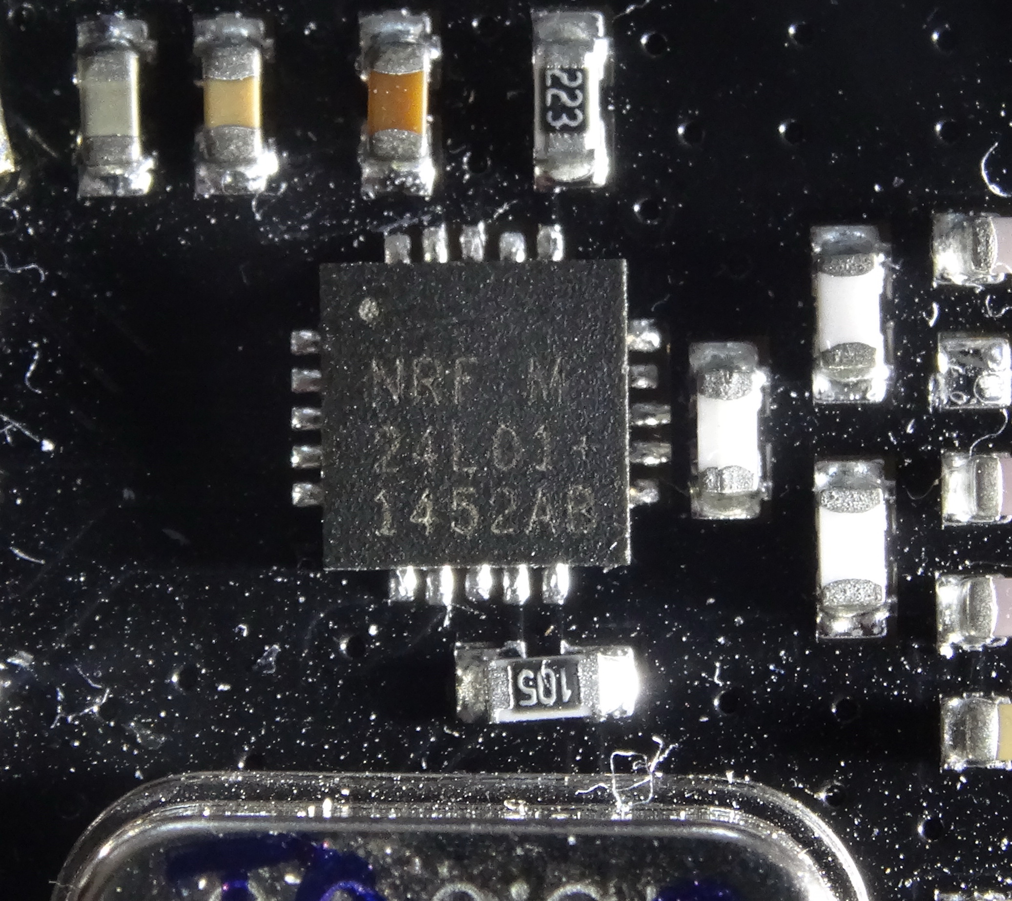
I checked the print and it is different to the cheap ones. But, I got genuine NRF24 chips (just the ICs) from mouser and this print is similar to the cheap ones!!??
Edit:
The print quality of cheap modules is not as good as genuine one and more space between dot and first line.
Genuine parts differ in little dot or square.ITEAD
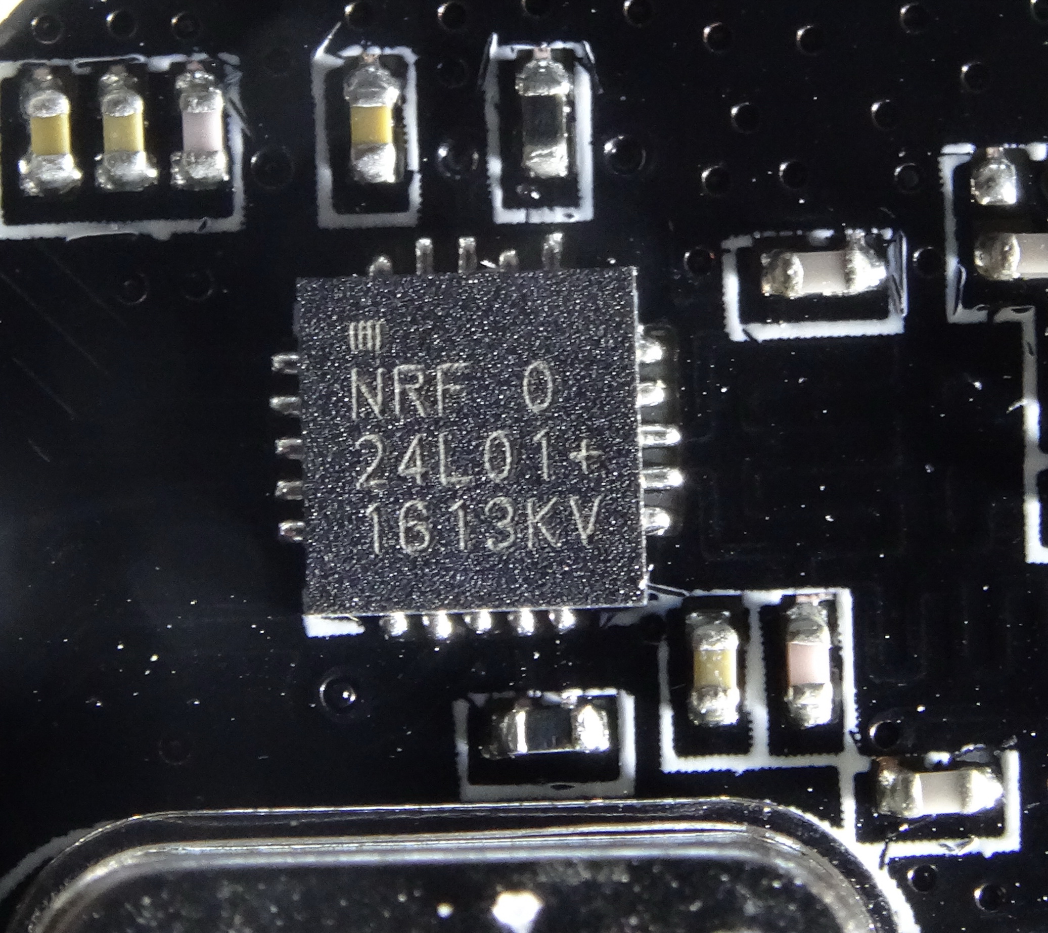
IC from Mouser
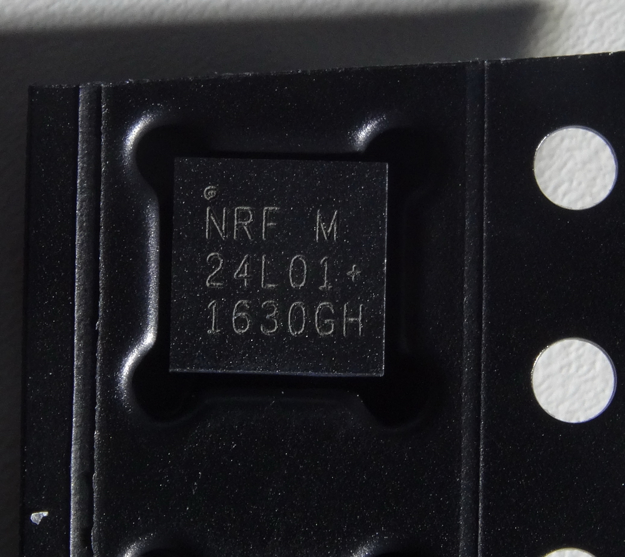
Cheap Ali/ebay
-
I checked the print and it is different to the cheap ones. But, I got genuine NRF24 chips (just the ICs) from mouser and this print is similar to the cheap ones!!??
Edit:
The print quality of cheap modules is not as good as genuine one and more space between dot and first line.
Genuine parts differ in little dot or square.ITEAD
IC from Mouser
Cheap Ali/ebay
-
@cimba007
I think I read somewhere in a different thread on this forum that the PA+LNA ones work better if powered from a lower voltage.@NeverDie: In addition to using RF24_PA_MIN I power most of my nodes from 2x AA Alkaline Batteries .. so they have 2.2V - 3,0V VCC. This might contribute to my pretty good reception.
Earlier nodes used 3,3V LDO in connection with lithium-ion batteries. So I can't say what really improved my reception the most ... lowering the voltage or putting the RF24_PA_MIN.
-
@NeverDie: In addition to using RF24_PA_MIN I power most of my nodes from 2x AA Alkaline Batteries .. so they have 2.2V - 3,0V VCC. This might contribute to my pretty good reception.
Earlier nodes used 3,3V LDO in connection with lithium-ion batteries. So I can't say what really improved my reception the most ... lowering the voltage or putting the RF24_PA_MIN.
just for comparison, my "geniune" has also the same logo and the cheap one looks much "better" but one can see the bad production quality
top one is GC supermarket, bottom genuine

-
@NeverDie: In addition to using RF24_PA_MIN I power most of my nodes from 2x AA Alkaline Batteries .. so they have 2.2V - 3,0V VCC. This might contribute to my pretty good reception.
Earlier nodes used 3,3V LDO in connection with lithium-ion batteries. So I can't say what really improved my reception the most ... lowering the voltage or putting the RF24_PA_MIN.
@cimba007 said:
@NeverDie: In addition to using RF24_PA_MIN I power most of my nodes from 2x AA Alkaline Batteries .. so they have 2.2V - 3,0V VCC. This might contribute to my pretty good reception.
Earlier nodes used 3,3V LDO in connection with lithium-ion batteries. So I can't say what really improved my reception the most ... lowering the voltage or putting the RF24_PA_MIN.
Anyone know what the optimal voltage range is for running the PA_LNA versions? It would be good to know for future reference.
-
@karlheinz2000
The first 2 definitely look similar, but the top left logo doesn't look genuine to me. But actually I don't care much about being genuine or not, the import thing is how they perform in terms of reliability and range@gohan said:
@karlheinz2000
But actually I don't care much about being genuine or not, the import thing is how they perform in terms of reliability and rangeAgreed. And it's not just the chip that will determine that, but rather the entire ball of wax.
-
I ordered modules from ITEAD. They seem to have real nordic chips populated. Each module comes in paper box and ESD bag. The modules look like the cheap ebay stuff, but with 0402 components.
With these modules I got rid of my issue with repeated messages.
(https://forum.mysensors.org/topic/5588/multiple-messages-with-same-content-received)@karlheinz2000 @parachutesj @gohan It appeared to be pointless to compare markings of nRF24L01+ IC's to determine if they are genuine or not.
Nordic is fabless and uses different fabs to produce their IC's. Each fab will have a different way of marking the chips.I had a discussion with a Nordic representative in the past and even he could only say for sure if an IC was genuine or not by putting the part in X-Ray.
He had 3 different modules analyzed which I mailed to Nordic (China versions); all 3 appeared to be fakes...The blob ones however are fake for sure.
http://yveaux.blogspot.nl
-
@karlheinz2000 @parachutesj @gohan It appeared to be pointless to compare markings of nRF24L01+ IC's to determine if they are genuine or not.
Nordic is fabless and uses different fabs to produce their IC's. Each fab will have a different way of marking the chips.I had a discussion with a Nordic representative in the past and even he could only say for sure if an IC was genuine or not by putting the part in X-Ray.
He had 3 different modules analyzed which I mailed to Nordic (China versions); all 3 appeared to be fakes...The blob ones however are fake for sure.
-
Since its impossible to determine if a radio is genuine, fake or even working (power consumtion in sleep mode for example) is there a good sketch and/or PCB to test the radio module?
-
Another user wrote me a few days ago that there are modules that work best with 4.7uF cap while others need higher capacity, so that makes it also more difficult to make a test rig. In addition I don't remember if there is a way to get signal quality from NRF24 (but I don't think there is) to help the tests
-
Since its impossible to determine if a radio is genuine, fake or even working (power consumtion in sleep mode for example) is there a good sketch and/or PCB to test the radio module?
-
@Yveaux
So basically we are stuck at trying modules from a supplier and share on the forum if they work or not, right?@gohan said in Which are the *best* NRF24L01+ modules?:
@Yveaux
So basically we are stuck at trying modules from a supplier and share on the forum if they work or not, right?WRONG. If you read this thread (search for "nailed it"), and if you have an oscilliscope, I show what seems like a 100% reliable way to differentiate between genuine and fake chips.
-
Another user wrote me a few days ago that there are modules that work best with 4.7uF cap while others need higher capacity, so that makes it also more difficult to make a test rig. In addition I don't remember if there is a way to get signal quality from NRF24 (but I don't think there is) to help the tests
@gohan said in Which are the *best* NRF24L01+ modules?:
Another user wrote me a few days ago that there are modules that work best with 4.7uF cap while others need higher capacity, so that makes it also more difficult to make a test rig. In addition I don't remember if there is a way to get signal quality from NRF24 (but I don't think there is) to help the tests
In this particular instance, if you're unsure which cap value to pick, pick the one with the biggest value. Overkill is better than underkill.
-
@gohan said in Which are the *best* NRF24L01+ modules?:
Another user wrote me a few days ago that there are modules that work best with 4.7uF cap while others need higher capacity, so that makes it also more difficult to make a test rig. In addition I don't remember if there is a way to get signal quality from NRF24 (but I don't think there is) to help the tests
In this particular instance, if you're unsure which cap value to pick, pick the one with the biggest value. Overkill is better than underkill.
Hello! It looks like you're interested in this conversation, but you don't have an account yet.
Getting fed up of having to scroll through the same posts each visit? When you register for an account, you'll always come back to exactly where you were before, and choose to be notified of new replies (either via email, or push notification). You'll also be able to save bookmarks and upvote posts to show your appreciation to other community members.
With your input, this post could be even better 💗
Register Login