Safe In-Wall AC to DC Transformers??
-
-
Last week I carried out an elektrical safety test on the HLK-PM01 to NEN 60101 (Dutch test for medical equipment) and it performed pretty well. I will try to post the file, after I removed some private information

Furthermore I am building a automated load tester that relates variable loads to output voltages and surface temperatures, based on an Arduino Nano.
-
@Bertb Great news! Looking forward to the results.
-
@Bertb said:
Last week I carried out an elektrical safety test on the HLK-PM01 to NEN 60101 (Dutch test for medical equipment) and it performed pretty well.

I can´t wait to see the results
-
@Bertb Cool, always handy to have people like you on forums
 I'm also looking forward to the results!
-
Maybe the "Samsung ETAOU10EBE" phone charger is also an idea to use. I have one for my phone, and it is very small.
I haven't opened it (i use it for my phone, dohhh), but the charger is small, so the PCB inside will be even smaller.It is 5V @ 700mA with a microUSB wire. I got a second one from eBay, which was being sold as 'genuine'. And to be honest, i really don't see any difference with the one that came with my phone. It is working fine for more than a year.
-
Well, here is the test file. I made it using test software named Ansur and a Fluke ESA640 tester in a Class II test setup.
The only problem is that some test results are in Dutch.
-
For us none dutch talking people... Good or Bad? (Yes, I see the big PASSED text
 )
)
-
@hek I'm Dutch but I also have troubles interpreting the results...
But hey, I'm a software guy!
-
i guess fluke can set to eng,thanks @Bertb for the results,think you don´t make it at home
-
Sorry for the language thing. I will try to get some tests in English in the future.
The tester used is designed for tests of medical equipment and this specific test proves that this specific HLK was safe. The problem is, however, that it does not prove anything with respect to the safety of other HLK's.In the mean time, the same HLK is feeding a load of 730 mA. It's output voltage is 5.08 volts and the case temperature is Temp
 46.81 Temp F: 116.26105.
@Didi. You are correct. I work in a hospital. I will try to setup the Fluke to English.
-
Wait Mike, there is more ...
I sacrificed a device to the altar of success and opened it.
That was not very difficult. After scratching away some gum stuff the following was revealed.
I will try to remove the rest of the gum with acetone. I will also do some heat and burn tests.This is quite funny to do

-
And I found the AP8012 chip inside. It has the following features:
_1286955514_oj99d4.pdf
-
@Bertb Thanks Bert! Good digging!
-
@Bertb thanks! Good detective work! It seems the chip provide all the protections needed. That is very encouraging
-
Thank you very much. I agree with you ap8012 seems to be a good chip. As we can see, it is difficult to make it smaller if we want all securities...and for the price including shipping I think they will sell lot of these things!
-
@Bertb it is hard to see from the photos, are the capacitors rated for 105c?
-
@Moshe. Yes they are. I did not yet dug into that, but is that good news?
-
Observe the air gaps.
I also tried to incinerate the gum stuff that is inside the module with a cigaret lighter.
After a couple of seconds it starts to glow, then, after some 10 seconds, the material starts to burn. But this stops within some 20 seconds ofter removal of the lighter.
I made a film, but it is too large to upload.I am not an expert on AC-DC converters, but I am quite impressed by the layout of the design.
The only thing that worries me is that I do not see how the OVP is created. On the other hand, this can be easily solved by adding a fuse and a ovp zener in the primary circuit.
-
@Bertb yes,although to be expected. Did you see the comparison mentioned a bit earlier in this thread? That is the first thing he checked
-
In the datasheet we can see it is implemented in the chip (in the block diagram) and how it works is explained at page 7. If VCC not well built, the chip would not work well I think.
-
I do not totally agree with this. When I take a look at the example circuit and read the ovp text, I can only conclude that the output is protected, because the circuit seizes to work when VCC rises to high. Whatever happens to the input circuit, I don't know. Therefore I prefer a fuse and and a varistor.
Have a look at the tutorial link text
-
@Bertb thank you for your testing!!! Although I don't know much about hardware I am gathering by the posts here that it is mostly good news!
So, now for the big question... If I were to add an external fuse like pictured here does everyone agree this is safe to put in a wall?
And, a follow up question if the answer is yes. Are there any basic tests we can do at home to verify the performance should be the same as what was tested here?
-
@Bertb, thanks a lot. I guess you mention to put a varistor/fuse right at output of this device, for example a 7K 14V varistor in parallel, and a 500mA fuse in series?
And what about the fire burn test --- Perhaps is there a method to measure it (and compare to some standard?).
-
I agree with you about varistor. it is a good idea.
-
I did not finish the automated power tester, but I put an HLK with a DS18B20 temp sensor in a closed flush box(is that the English word for the box in the wall, used for domestic wiring?).
A simple resistor acts as a load and draws a 800 mA from the power supply. That is 33% more than the max continuous value. Voltage across the leads is 4.96. That is 5.08 without load. Not too bad. At 600 mA (100% load) the voltage is also 5.00.
The Dallas says that the surface temperature at the HLK is 48.19 c ( F: 118.74).
Also do not forget to mount adequate capacitors to reduce ripple.@petewill and @rvendrame ... Every country has directives regarding flammability. I cannot say which one is valid. I have seen some testing in the past. They put a burner under the device under test and waited to see what happened after removal of the source. In general (without any warranty whatsoever) when there are no flames or when they extinguish autonomic is good. If there is no hot material dripping from the DUT, that is also good. The test I carried out is described above. No dripping en self extinguishing. So I am satisfied.
Sorry, I cannot be more specific. I do not have the knowledge.@rvendrame: yes the fuse in series in the mains live wire en the varistor in parallel with the primary side of the HLK.
With respect to the varistor ... see the sheet below:
Take a value that is well above the normal AC tension of your mains power, but below the max input voltage of the HLK. so in Netherlands 250 volts will do.
-
Now for the million dollar question ... would I mount a HLK in a flush box?
Well ... when equipped with varistor and fuse and with the load on the safe side ...
Yes, I would.
-
@Bertb, thanks again. I got a bit confused, do you mean put the varistor + fuse into the PSU input (AC Mains)? I was more thinking in over voltage protection on output. So a low-volt varistor together with a fuse/ptc, both on the 5V output.
My concern is having something wrong into the PSU-PWM control, and somehow the AC mains leaking to the low-volt side, cause arduino+friends burn/flaming. But I'm a hobbyist, so maybe I'm guessing wrong here.
Maybe to be on safest side --- varistor + fuse/ptc on both AC mains and 5V rails?
-
My initial safety is always toward the biggest danger ... mains in this case.
For the secondary part a simple semiconductor fuse and a zener (transzorb) will do.
-
@Bertb that is actually a very good surface temp for overload from what I saw in the other tests. Very promising.
-
At 535 mA, the temperature stabilizes at 39.81c /F 103.66
-
From what I researched at internet, the most important safety measure is the isolation part. Most countries have similar standards. From the pictures above I see the PCB tracks from high and low voltage are clearly separated by at least 0.5cm , which I think is also a requirement in EU.
Maybe if we figure out a way to provide something between 7.5Kv and 10Kv into the its AC input for some seconds/minutes, and see what happens. This is the worst-case scenario --- A lightning event into the AC line during a electrical storm.
Despite it may (and will) burn inside completely, any high voltage should never be present at output, as well as no significant flame that may propagate fire should occur.
This of course requires costly and sofisticated lab equipment.
-
The specs of the unit states that it resilient to high voltages. I tested it with 250 VDC across input and output.
As stated before in this threat, the specs are ok, it only lacks the stamps.
From what I have seen so far, the module is good for me.From the specs:
4.Safety Characteristics:
4.1Products designed to meet UL, CE safety certification requirements.
4.2Safety and electromagnetic compatibility
Designed with the input of 0.5A UL certified insurance;
PCB board using double-sided copper clad plate production, material for the 94-V0 fire rating level;
Safety standards: Compliance with UL1012, EN60950, UL60950
Insulation voltage: I / P-O / P: 2500VAC
Insulation resistance :I / PO / P> 100M Ohms / 500VDC 25 ℃ 70% RH
Conduction and radiation :comply with EN55011, EN55022 (CISPR22)
Electrostatic discharge :IEC / EN 61000-4-2 level 4 8kV / 15kV
RF radiation Immunity: IEC / EN 61000-4-3 See Application Note
4.3 Temperature safety design
At room temperature,the capacitors of this power , the inner surface of the main converter maximum temperature does not exceed 90 ℃;
Shell maximum surface temperature does not exceed 60 ℃
-
Overall that looks like a pretty good AC/DC trans. The isolation boundary looks massive.
-
@rvendrame @Bertb this guy detail his methods here http://lygte-info.dk/info/usbPowerSupplyTestHow UK.html
he has some kind of gadget that produce 2500v to 5000v.
Anyway, I am convinced that this is safe (or at least MUCH safer then what people here have been using). If one of the electrical wizards can detail the circuit with extra fuses, diodes and varistor (what is that???) I think it can help us all.
-
@Moshe Livne, yes I think I saw that website. The list of equipment there is surely respectable, at least. I just wrote to the info@ there, asking if perhaps he would like to test one of this HLK PSU. I can send one or two of my lot, lets see if we get some reply.
The varistor is a device widely used for protection. It is connected in parallel with the AC mains. It will short the circuit in case the voltage exceeds its pre-determined value. The ideia is to use it burn an internal fuse, or trigger the house circuit breaker in case of over voltage. A 20K-250V varistor will short the circuit if voltage is above 250V, and it supports voltages up to 20KV without produce any flame.
Using a varistor in conjunction with a PTC fuse (a fuse that automatically resets after some time) creates a very good protection for over voltage, with small cost and footprint.
I do agree with @Bertb and @ServiceXp , this HLK PSU looks good and safe for what we intend to use. Surely it is better than a phone charger. But as in any DIY, each one of us must know where to step on, assuming the involved risks.
-
@Bertb I live in the Netherlands just like you. If you're interested i can make some thermal images of the disassembled HLK unit if you send it to me. I expect my FLIR One (Android) to arrive probably next week.
-
Just to be sure everybody understands the schematic, hereunder a schematic.
I am not a fan of blowing mains fuses ...
-
@ThinkPad I am not sure it is still safe to operate.
-
@Bertb The idea was to put it on my desk (with a mains cord soldered to it) running a resistor load, and then shoot some thermal pics of it
. I wasn't planning to touch the unit with my bare hands while it is powered hahaha
-
@ThinkPad Well its your desk, so its fine with me.
Is there a way to get your address without shouting it from the rooftops?
-
Don't suppose anyone could tell me what components (values) need to be purchased for 230v (UK)? I have bought 10 of these and wish to make them as safe as I can.
-
@Bertb Have sent you a chat, see the chat balloon top right corner.
-
@Atomfire I will come back to that tomorrow.
-
@Bertb Once again, thank you for all your work with this! I can't wait to start building with this! This will be so helpful to have a safer method instead of just dismantling old phone chargers and rolling the dice.
I couldn't open the schematic. What is the file extension? Also, would you mind posting the required parts for 110v if they are any different than what you will be providing @Atomfire?
Thanks!
Pete
-
Hey guys, I wrote to the owner of the site suggested by @Moshe-Livne. He replied saying that he can test the HLK.
He mentioned that usually he takes at least two units (so if one burn he can continue the testing). I will send one from my lot, perhaps we have a brave guy to gave up one more? (a sacrifice of few to save many )
 Let me know and I will share the address via PM (Denmark).
-
@rvendrame Considering cost of postage and logistics involved it would probably be cheapest to just order two units from Ali to him? its 8$ including shipping if i remember correctly
-
@petewill The schematic is just a simple draft. It can be seen with IE.
-
@Bertb I tried adding "html" suffix to it but it didn't work.
-
One option is to click on the link and download the file. After the file is completely downloaded, just add the extention .jpg to it.
The result is as following:
-
Something went wrong with uploading the file, I think.
Herewith a new schematic with a suggested bill of material.
It is highly experimental still, but I ordered the components yesterday.I am specially interested in working with the PTC fuse.
I hope the proposed circuit works for you. Please keep the maximim continuous output power in mind. It is only 3 Watts (600 mA).
In some cases you might need to add C1's (rule of thump 1 per chip or chip VCC) and/or need to increase the value of C2. This depends on the fluctuations in the power demand.With the proposed values for C1 and C2, the ripple remained below 50 mV at 500 mA.
Also keep in mind that a remaining oscillation frequency residue appears in the output of some 60kHz.. If capacitors are not able to filter that out, a small coil might be needed.Well it is experimenting that makes this fun, isn't it?
-
@rvendrame said:
Hey guys, I wrote to the owner of the site suggested by @Moshe-Livne. He replied saying that he can test the HLK.
He mentioned that usually he takes at least two units (so if one burn he can continue the testing). I will send one from my lot, perhaps we have a brave guy to gave up one more? (a sacrifice of few to save many )
 Let me know and I will share the address via PM (Denmark).
I am in for this.
-
@rvendrame said:
Let me know and I will share the address via PM (Denmark).
I will send him a powersupply too.

-
@Bertb can now see the scheme! thanks. But can't see the BOM
-
... it must be friday ...
-
-
As you please ...
-
-
I managed to borrow a Megger (high voltage resistance measurement device). This weekend I will test the insulation of the MLK.
The only drawback is that the Megger reaches to 1000 Volt.
-
@Moshe-Livne said:
@rvendrame Considering cost of postage and logistics involved it would probably be cheapest to just order two units from Ali to him? its 8$ including shipping if i remember correctly
Yes, it makes all sense. The only downside is that if we buy all at same time probably he will get all from the same lot, but in my opinion it by far doesn't invalidate the testing.
So, myself, @Bertb , @Didi = 3 PSUs, better than 2. I will share with you both the ship-to address ok? Thanks a lot!
-
@rvendrame said:
So, myself, @Bertb , @Didi = 3 PSUs, better than 2. I will share with you both the ship-to address ok? Thanks a lot!

-
I'm really happy to hear that these HLK power modules are considered to be safe. I've been using them for a few weeks already, but didn't have a clue what was inside (and whether they were ACTUALLY safe).
One question regarding the varistor and PTC fuses though:
Any reason (or specifications) why you chose those specific components? I've been looking for myself as well, but came up with slightly different components.Fuse1 and 2: PTC Resettable Fuses 250V 1A TRF250-1000
Varistor1: [10D391K 10K391 390V varistor diameter 10mm AC 250V DC 320V]
(http://www.aliexpress.com/item/Varistor-10D391K-10D-391K-VDR-10K391-Metal-voltage-dependent-resistor-50pcs-bag/1912418587.html)Varistor2: [5.5V Varistor original Varistor resistor]
(http://www.aliexpress.com/item/SMD-1206-5-5V-Varistor-original-Varistor-resistor-100pcs-lot/32243046238.html)If anyone with a bit more experience could have some feedback on these components, that would be really really appreciated!!
-
@rvendrame said:
@Moshe-Livne said:
@rvendrame Considering cost of postage and logistics involved it would probably be cheapest to just order two units from Ali to him? its 8$ including shipping if i remember correctly
Yes, it makes all sense. The only downside is that if we buy all at same time probably he will get all from the same lot, but in my opinion it by far doesn't invalidate the testing.
So, myself, @Bertb , @Didi = 3 PSUs, better than 2. I will share with you both the ship-to address ok? Thanks a lot!

-
@aproxx I would say that the 50 mA fuse is too weak. The HLK draws between 0.1 and 0.2 Amp and can surge 10 Amp. So, I think the 1A version is good for both situations input and output. The varistor is only good for the output.
One thing to consider though. This is also chinese stuff ... is it really safe or are we introducing a new problem?
-
@Bertb Aaah yes now I see. It does seem to draw much more peak current than I expected! Then I'll just use the same component as I'm using for Fuse 2.
What do you mean by "The varistor is only good for the output."? You're using one as input and one as output in your diagram as well or am I missing something?And yes, I know this is Chinese stuff again.. But single (chinese) components never failed on me (until now).

-
@aproxx The only varistor I see in your list is 5.5 Volt.
-
@Bertb I see what is getting both of us confused.
Apparently something was wrong in the link of my previous post, resulting in the 2nd varistor not being listed. So now your comment about the varistor only being good for the output makes sense as well.
I've fixed the link of my post above!
-
@aproxx This is a different kind of notation, but when I look the device up in de Bourns catalog, I see it is rated for 250 Vac. That should be good.
-
Short update ... yesterday I asked or Chinese friends from Alie to send a HLK module to our test friend.
I also did an insulation test with 1000 Volt. The test shows more than 1000 MOhm between ac and dc. So far so good.
-
Not a big fan of soldering SMD components and I cannot find standard components, how essential is the 2nd fuse and varistor on the 5v side?
-
@Bertb said:
Short update ... yesterday I asked or Chinese friends from Alie to send a HLK module to our test friend.
I also did an insulation test with 1000 Volt. The test shows more than 1000 MOhm between ac and dc. So far so good.
-
@Atomfire said:
Not a big fan of soldering SMD components and I cannot find standard components, how essential is the 2nd fuse and varistor on the 5v side?
We are trying to make it as safer as possible... Assuming such modules will stay in a wall box, very close to wires and/or other potential fireable materials, we should try to mitigate risks as much as possible.
As I mentioned above --- This is DIY, also means 'risk it yourself'. Don't tell your insurance company

-
@rvendrame said:
@Atomfire said:
Not a big fan of soldering SMD components and I cannot find standard components, how essential is the 2nd fuse and varistor on the 5v side?
We are trying to make it as safer as possible... Assuming such modules will stay in a wall box, very close to wires and/or other potential fireable materials, we should try to mitigate risks as much as possible.
As I mentioned above --- This is DIY, also means 'risk it yourself'. Don't tell your insurance company

That is why I prefer to use fuses that blow, like the ones I mentioned earlier.
The resettable fuses also get warm. Can't wait for the package from Conrad to arrive. I am dying to do some further testing.With respect to the brave HLK ... it is on for some three days and it is stable.
-
@Bertb said:
That is why I prefer to use fuses that blow,
In the other hand, you have to disassemble the wall box in order to reach regular fuses that eventually blow. So I tend to prefer PPTCs, at least for this 'discovery' phase.
But it is just my personal preference.
-
Thanks everyone for the help! I don't know much about this stuff and I am grateful to you for all your contributions!
I am starting to look at ebay for parts but I was wondering if it would be wise to wait a little longer before I order and more testing is performed? I am excited to start building but I don't want to do anything until it's safe. I know safe is a relative term so I guess I should say safe enough for you all to use in your houses.

Thanks again!
Pete
-
@petewill I think this is a wise decision.
I liked the discussion on this thread, so I have to thank you too.Now it is waiting time. Waiting until the hlk-s arrive at the lab of the test guy.
My Chinese friend said, the package is on its way.
-
Mine is on the way too.
-
@Bertb thanks, will do. The waiting is the hardest part

-
Just a heads up. Yesterday I blew up this module, which I bought some time ago (before we invest into the HLK analysis).
I really don't know what happened, it simply exploded without any further notice (and very near my face, like 30cm or so). I was calibrating the power sensor. Dummy I was, trying to find why it was measuring 10W while the PSU is rated 3W...
The sensor is based on a current transformer TA12-100 , measuring itself on ACMains.
Perhaps some old-school guy can tell me if I violated some some basic rule? I want to believe that some scrap wire or metal has shortened some track, but how to prove it?
Well after that, I measured the arduino + radio + measurement circuit and it never crossed 30mA... I also replaced the damaged PSU (by one identical), and now the power sensor measures 4W (instead the previous 10W), and despite some noising capacitor, no heat or instability after 12 hours or so on.
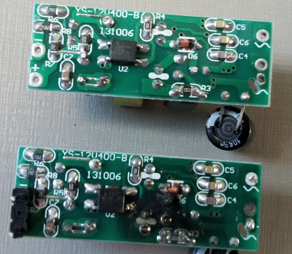
Pictures of the occurrence:
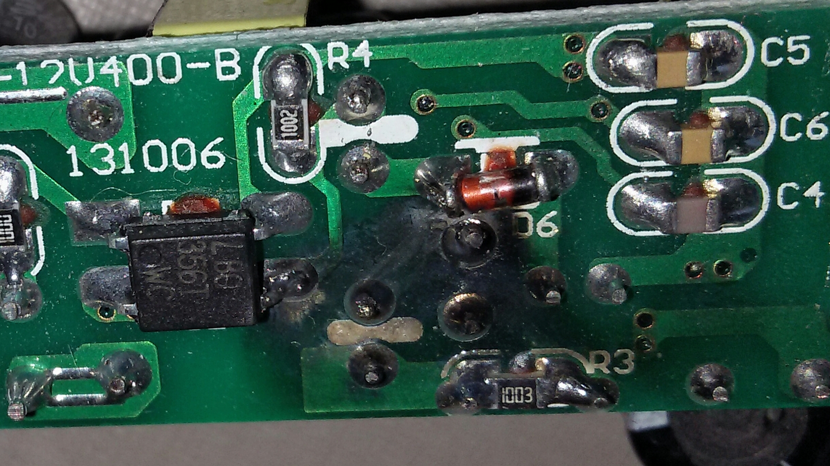
Botton one is the damaged one:
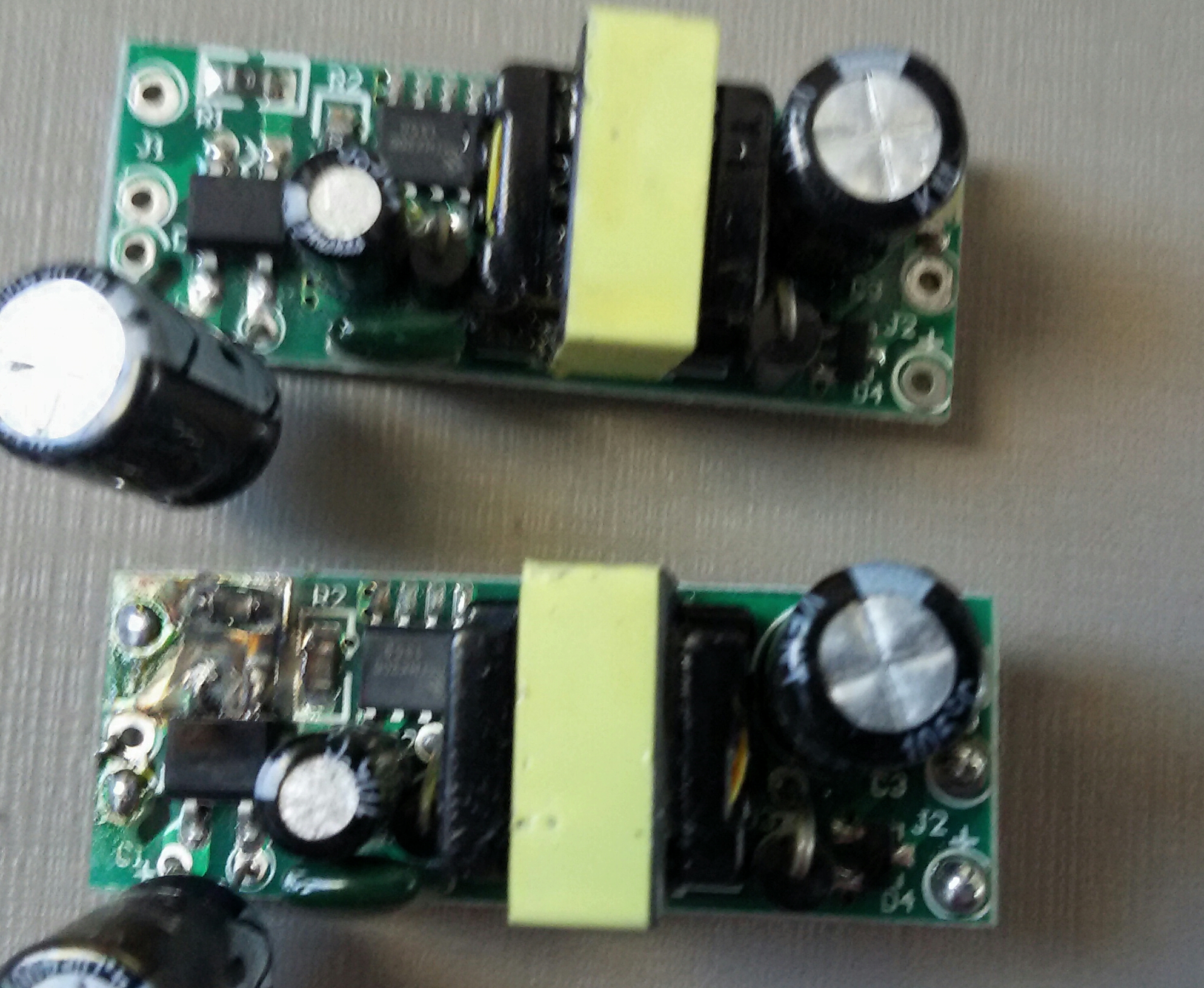
-
@rvendrame Whatever happened (looks like something went to ground; were you probing with a scope?), that MB6S was the source, because that rectifier is blow out.
I don't think you will be able to buff that one out...

-
@ServiceXp , no
-
@ServiceXp , no oscilloscope. I was Cheking why the power sensor was measuring 10w instead 3w or less.
The CT sensor was around the mains phase wire, and the psu was powering the sensor. I didn't change anything , just multimeter readings on DC side. Didn't touch the ac mains except to insert the current transformer around it.
I also connected a light bulb on same wire, in order to generate some load. The sensor was measuring the bulb correctly, however when the bulb was disconnected it read 10w, away too much for only an arduino.
-
@rvendrame I'm not sure if I really get your setup, but ground loops can be a very nifty cause of all kinds of stuff getting 'too hot'

Could this be the cause of the problem?
That 0 ohms resistor also looks like it been fried. What's its use on the board?
-
@rvendrame Hard to say then, but I'd bet an ice cream sandwich that something went to ground/neutral. It's the high voltage side that is blown out of that rectifier.. You may never know what the cause was.
-
@petewill when you start home automation at that time please share photos wit me.
how to setup the no. of relay, power supply, arduino, radio etc in WALL box.
-
@jemish yes, that's the plan. Once all the geniuses figure out how to do it I plan on making a how to video

-
Is there any news from the test guy?
-
yes , is there any news
-
@Didi, did you end up doing horrible things to these? You said something about flashbox?
-
If the fellow behind http://lygte-info.dk/info/usbPowerSupplyTestHow UK.html posts good results on his website, the supply chain should prepare for a flood of orders! I've seen those tests widely referenced, and I think a lot of people are looking for something safer but still cheap.
Don't be surprised if a positive review made it to HackaDay and the like as well.
(Get your ali orders in now, beat the rush - if you think it will come out well)
-
I'm also looking forward about test results. I've seen the module however never totally trusted; until I found this topic. The price and size are perfect for under-socket installation. If further results come out good, I'm eager to see in-wall projects.
-
This one is not "safe", but it is an In-Wall AC to DC converter. Transformerless. With a 3A Solid state relay:
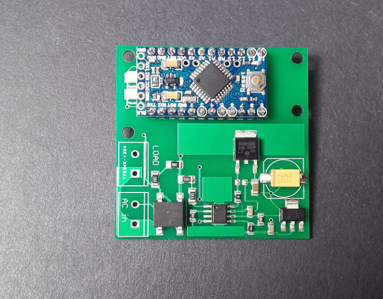
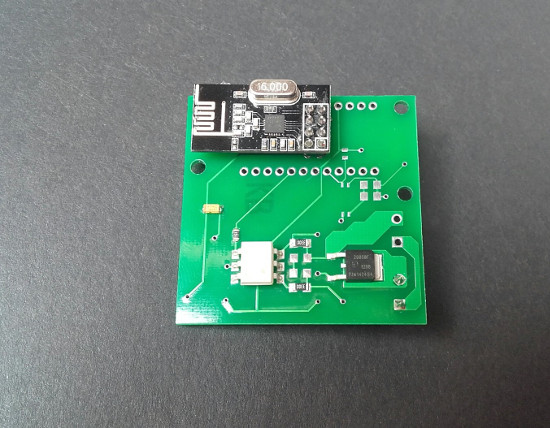
The converter output is 3.3V at 100mA and the solid state relay is a Triac.
-
Looks very nice, but you cannot use it for sensors or actuators that can be touched by hand and do not comply with the insulation standards, since parts of it will be connected to mains.
-
@Bertb Yes, it shouldn't be touched. It can be used with wall-mounted mains switches, though. Placed behind it.
-
Did anyone look at the SwitchMote PSU over at LowerPowerLab? More info here. The kit is fairly expensive ($30) but I wonder how much it would be to source the components yourself since someone else has done all the design work.
-
@TD22057 I would say the cost of this PSU is dominated by the Recom converter onboard. Farnell charges E14,58 for single pieces (http://nl.farnell.com/recom-power/rac02-05sc/ac-dc-converter-2w-5v-reg/dp/1903060?searchRef=SearchLookAhead).
Rest of the components will be a few Euro's, and ofcourse the PCB (which contains a number of milled slots for isolation).
All together you will get fairly close to $30 when building it yourself.
-
@ceech said:
Yes, it shouldn't be touched
Nice! just label board !LIVE!
Not safe due to no fuse? Do share, making your own boards with solder mask?
-
@DrJeff the board is not isolated from mains by e.g a transformer. This means traces carry live mains!
-
So basically it is like any other consumer Zwave switch or X10 just box it up (3D printer on stand by) with 2 micro buttons with a rocker face and I want 10.
 But sorry I digressed from the OP in my excitement.
-
@DrJeff As @Yveaux said the board does not have an insulation transformer. Yes, I make them. And it works fine, placed inside an enclosure is as safe as it could be. Would you make a box for it? I can send you one board if you like, for the measures.
