💬 Soil Moisture Sensor
-
I use A0, A1
2018-08-12 01:31:11.969 [vent.ItemStateChangedEvent] - MoistHum changed from 11 to 9642018-08-12 01:31:42.386 [vent.ItemStateChangedEvent] - MoistHum changed from 964 to 121
2018-08-12 01:31:42.440 [vent.ItemStateChangedEvent] - MoistBat changed from 42 to 43
2018-08-12 01:32:13.860 [vent.ItemStateChangedEvent] - MoistHum changed from 121 to 299
2018-08-12 01:32:45.300 [vent.ItemStateChangedEvent] - MoistHum changed from 299 to 129
2018-08-12 01:33:16.717 [vent.ItemStateChangedEvent] - MoistHum changed from 129 to -11
2018-08-12 01:33:48.132 [vent.ItemStateChangedEvent] - MoistHum changed from -11 to -101
2018-08-12 01:34:19.528 [vent.ItemStateChangedEvent] - MoistHum changed from -101 to 514
2018-08-12 01:34:50.943 [vent.ItemStateChangedEvent] - MoistHum changed from 514 to 1478
2018-08-12 01:35:22.355 [vent.ItemStateChangedEvent] - MoistHum changed from 1478 to -265
What do I connect wrongly? the results are not true
-
Hi, I'm trying to get my first sensor to work and I followed this guide https://www.mysensors.org/build/moisture
I got my gateway to work and the sensor got discovered in openhab. But I think the values I'm getting are quite odd and I don't think it's working as intended for me.
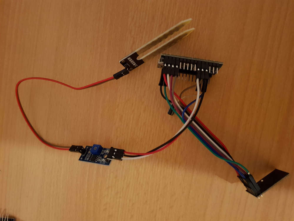
That's my setup, just like on the guide. When I put the sensor it into water, 2 LED start to light up on the small blue board.
I decreased the SLEEP_TIME for testing purpose and here's what I'm getting:
https://pastebin.com/e93P86aY (too many characters to post it directly here)
while this measuring, I put it several times into a cup with water and I dried it. Should negative values even happen? I'm not sure how to work with those values.
It feels like, it's just giving me random numbers without actually measuring something.
-
Hi @atzohy
The info in the page is confusing. The small board between the sensor and the arduino is an on-off level switcher. It provides a digital binary singnal so can't be connected to an analog pin on the arduino.
If you wish to measure the moisture level with an analogic scale, you need to eliminate that board and then use a voltage divider and an analog pin. The sketch will be also different. Everything in explained above in the thread.
You may want to read the full thread and then don't hesitate to come back with your questions.
-
Hi,
I have this message :
16 MCO:BGN:INIT NODE,CP=RNNNA---,FQ=16,REL=255,VER=2.3.2
26 TSM:INIT
28 TSF:WUR:MS=0
34 !TSM:INIT:TSP FAIL
36 TSM:FAIL:CNT=1
37 TSM:FAIL:DIS
39 TSF:TDI:TSL
10041 TSM:FAIL:RE-INIT
10043 TSM:INIT
10049 !TSM:INIT:TSP FAIL
10051 TSM:FAIL:CNT=2
10053 TSM:FAIL:DIS
10055 TSF:TDI:TSLWhat is the problem please ?
I'm noob.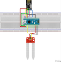
Thank you
-
Hi,
I have this message :
16 MCO:BGN:INIT NODE,CP=RNNNA---,FQ=16,REL=255,VER=2.3.2
26 TSM:INIT
28 TSF:WUR:MS=0
34 !TSM:INIT:TSP FAIL
36 TSM:FAIL:CNT=1
37 TSM:FAIL:DIS
39 TSF:TDI:TSL
10041 TSM:FAIL:RE-INIT
10043 TSM:INIT
10049 !TSM:INIT:TSP FAIL
10051 TSM:FAIL:CNT=2
10053 TSM:FAIL:DIS
10055 TSF:TDI:TSLWhat is the problem please ?
I'm noob.Thank you
@Diazovitch69 You can use the log parser : https://www.mysensors.org/build/parser
16 MCO:BGN:INIT NODE,CP=RNNNA---,FQ=16,REL=255,VER=2.3.2	Core initialization of NODE, with capabilities RNNNA---, CPU frequency 16 MHz, library version 2.3.2, release 255
26 TSM:INIT	Transition to Init state
28 TSF:WUR:MS=0	Wait until transport ready, timeout 0
34 !TSM:INIT:TSP FAIL	Transport device initialization failed
36 TSM:FAIL:CNT=1	Transition to Failure state, consecutive failure counter is 1
37 TSM:FAIL:DIS	Disable transport
39 TSF:TDI:TSL	Set transport to sleep
10041 TSM:FAIL:RE-INIT	Attempt to re-initialize transport
10043 TSM:INIT	Transition to Init state
10049 !TSM:INIT:TSP FAIL	Transport device initialization failed
10051 TSM:FAIL:CNT=2	Transition to Failure state, consecutive failure counter is 2
10053 TSM:FAIL:DIS	Disable transport
10055 TSF:TDI:TSL	Set transport to sleep
The initialization of the transport is failing. So there is a problem between your arduino? and your radio module.
You should check your wirings! -
Hi,
I have this message :
16 MCO:BGN:INIT NODE,CP=RNNNA---,FQ=16,REL=255,VER=2.3.2
26 TSM:INIT
28 TSF:WUR:MS=0
34 !TSM:INIT:TSP FAIL
36 TSM:FAIL:CNT=1
37 TSM:FAIL:DIS
39 TSF:TDI:TSL
10041 TSM:FAIL:RE-INIT
10043 TSM:INIT
10049 !TSM:INIT:TSP FAIL
10051 TSM:FAIL:CNT=2
10053 TSM:FAIL:DIS
10055 TSF:TDI:TSLWhat is the problem please ?
I'm noob.Thank you
@Diazovitch69 I have a hard time zooming in the provided wiring, so I can't check it. But as evb says, it looks like the radio isn't connected right. So either it's not wired correctly or you could have a broken radio.
The things I normally do when I encounter this, is first check and double check the wiring. I also measure the individual cables in the dupont cable. It happened to me once I had bought a broken cable. Or another problem I once had, was that the power and ground rail of the bread board weren't connected from the left to the right section. Some broad boards have them connected others don't have that so you need to connect them in the middle.
I even got a free arduino once. Because I was convinced everything was correct so I contacted the supplier and he send me a new Arduino. I replaced it and still the same problem lol. Then I measured and found the cause.
If you're sure the wiring is correct. I'd try out another radio. Be sure that power radio with 3.3v and not 5V.
-
Hi,
I see in the pictures of the connection that the soil sensor is attached to 3.3V, GND and D3 but I can't see where D3 is named. How do you obtain a read from D3 if it isn't named in the code?
@Newzwaver d3 is called just 3 in the arduino IDE for atmel boards. Only the analog pins have an A suffix. But pin 14 is also A0.
Not sure if it answers your question. I'm on a lunch break :)
Hello! It looks like you're interested in this conversation, but you don't have an account yet.
Getting fed up of having to scroll through the same posts each visit? When you register for an account, you'll always come back to exactly where you were before, and choose to be notified of new replies (either via email, or push notification). You'll also be able to save bookmarks and upvote posts to show your appreciation to other community members.
With your input, this post could be even better 💗
Register Login