Try this one.
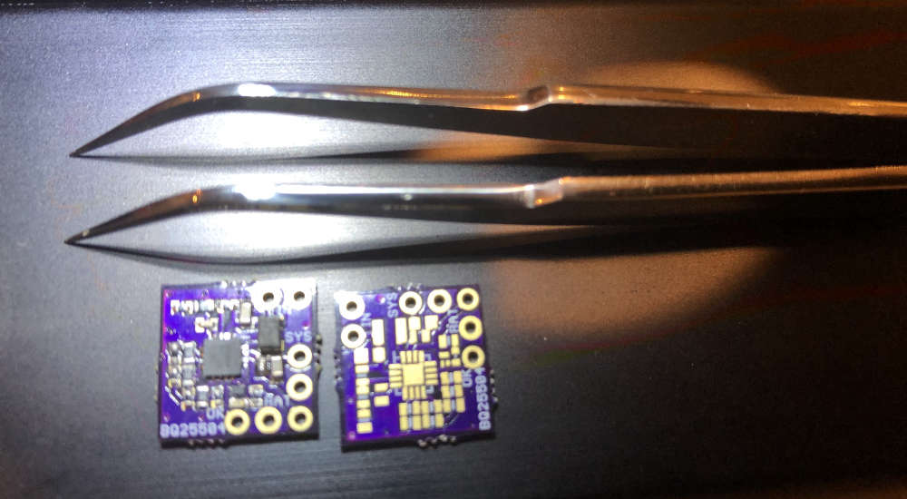
The smallest board I have ever assembled using just a hot fan. A solar battery charger based on BQ25504 from a solar panel. Almost all components are 0402. Far too small for my liking, but can go under the solar panel.
Best posts made by alexsh1
-
RE: What did you build today (Pictures) ?
-
2xAA powered PIR
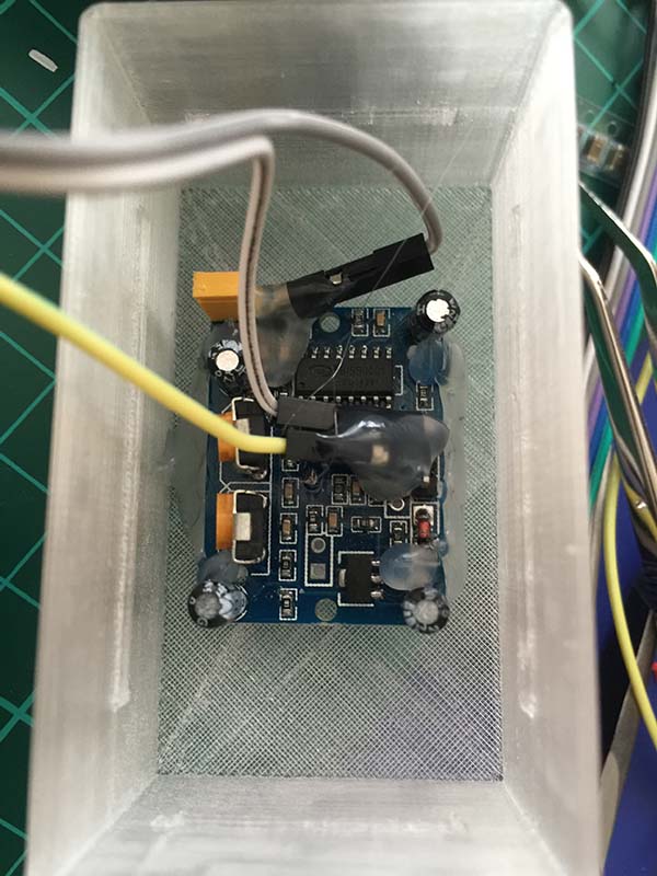
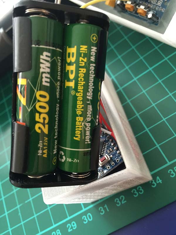
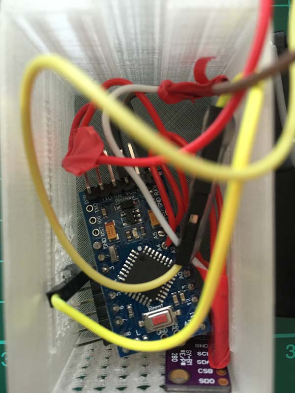
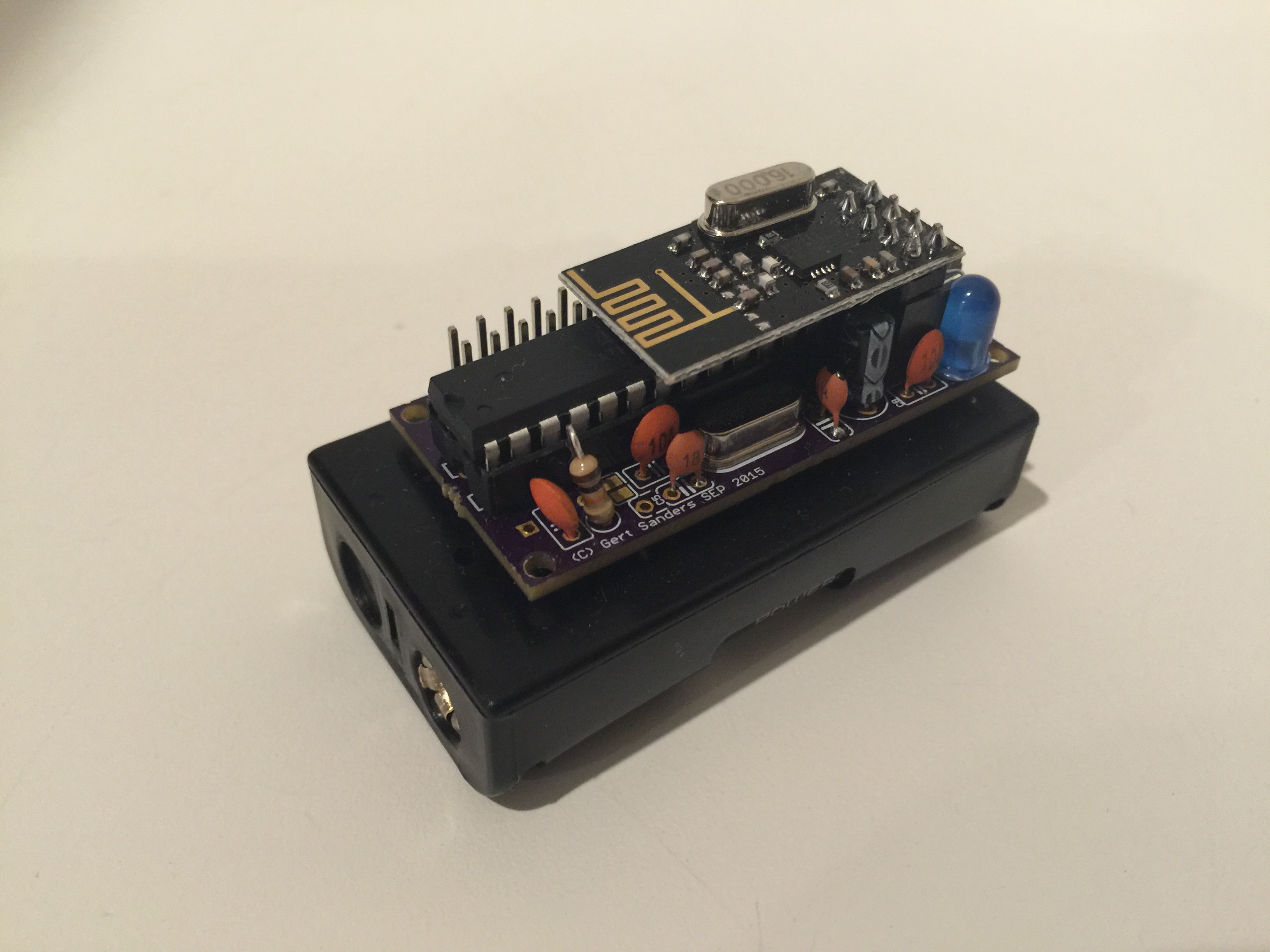
Took me a while to make it though the idea is very simple. I took this jModule https://www.openhardware.io/view/20/jModule and a BMP280 i2c board (I have a few spare ones) and hooked them up Mini Pro (modified for the battery use) as well as the PIR and the battery compartment. I have to admit I am cheating here - I am using 2xAA Ni-Zn and they are 1.6V each giving me a stable voltage 3-3.2V throughout its life.
I had to do a little modification to the PIR to be able to work at 3.3v. It does work really well. Cannot say much about the battery life as it depends. Sleeping current is low, but the life really depends on how many times the PIR is going to be triggered.Some photos at the end:
And the final product is ...(compared with DHT22)
-
RE: Step-by-step procedure to connect the NRF24L01+ to the GPIO pins and use the Raspberry as a Serial Gateway (MySensors 1.x)
@ahmedadelhosni said:
Is connecting the nrf directly to the pi causes any problems and u need to restart it ?
No, I have not had any big problems. The problem may only be the nrf24l01+ - I had to have a few changed plus fix the con to make it work. Wiring could be an issue. Also pay attention to CE pin.
CE Pin = Custom GPIO25 (I have Custom GPIO22) - this can be changed by the constructorExcellent write-up
-
RE: Fewer home automation postings? What's behind it?
@neverdie Nope! I meant riding
-
RE: 2.4" TFT: does it work with MySensors?
@jsiddall Yes, it does work. However, you may have to spend some time looking for a screen processor and schematics as Chinese are not providing much information.
-
Ask for schematics and have a look - there are four digital pins on your Arduino used for the SD card. Disolder these pins (some screens do not have them). These can be used for nrf24l01+ with Soft SPI (you have to enable it in MyConfig.h and change MISO, MOSO and SCK pins to correspond the pins you use).
-
Please do a bit research on Arduino forum. There is a sketch to help you to define a screen processor, there is a new library etc tons of information available.
-
It may take a while to do the whole research - there are many-many posts.
I have tried recently three different screens 2.8-3.2 (one similar to yours with analogue pins) with MySensors and all of them were working. Abeit one was very difficult - took me a while to
take it work due to lack of documentation.I posted some pictures in "Scene Controller" under "Development" - please have a look
PS @mfalkvidd provided excellent links
-
-
New Moteino M0 is out!
Hello
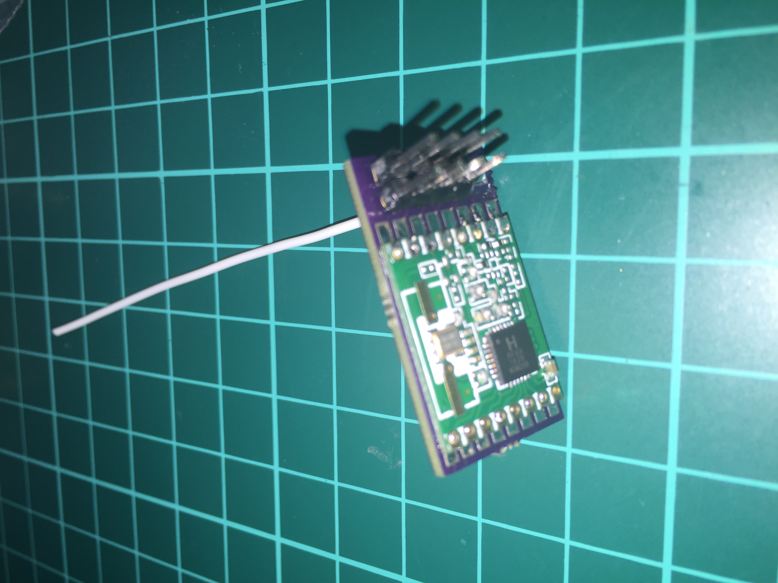
Some of you may have followed discussion at low power lab about a new ARM module. Here we go available to purchase now:
https://lowpowerlab.com/2018/05/27/moteino-m0-released/#more-2427
Felix also introduced a modular system (“sandwich board”). Absolutely fantastic!
-
RE: 💬 NRF2RFM69
I have just soldered rfm69w module to the adapter. All works just fine
-
RE: Please add a guide for how to connect use the RFM69(H)W
@hek I can confirm that Moteino Mega USB (and I think Moteino Mega as well) works out of the box:
Starting sensor (RRNNA-, 2.0.0-beta) Radio init successful. find parent send: 255-255-255-255 s=255,c=3,t=7,pt=0,l=0,sg=0,st=bc: find parent send: 255-255-255-255 s=255,c=3,t=7,pt=0,l=0,sg=0,st=bc: Init complete, id=255, parent=255, distance=255 find parent send: 255-255-255-255 s=255,c=3,t=7,pt=0,l=0,sg=0,st=bc:
-
RE: [solved] Moteino Mega -> cannot compile 2.2.0 beta
@scalz My avr is 1.6.18 (newest)
I'll pull the latest dev and try again.EDIT: Thanks @tekka - I have corrected pins_arduino.h for Moteino Mega (attached)
-
RE: atmega328p small (SMD) alternative with more memory?
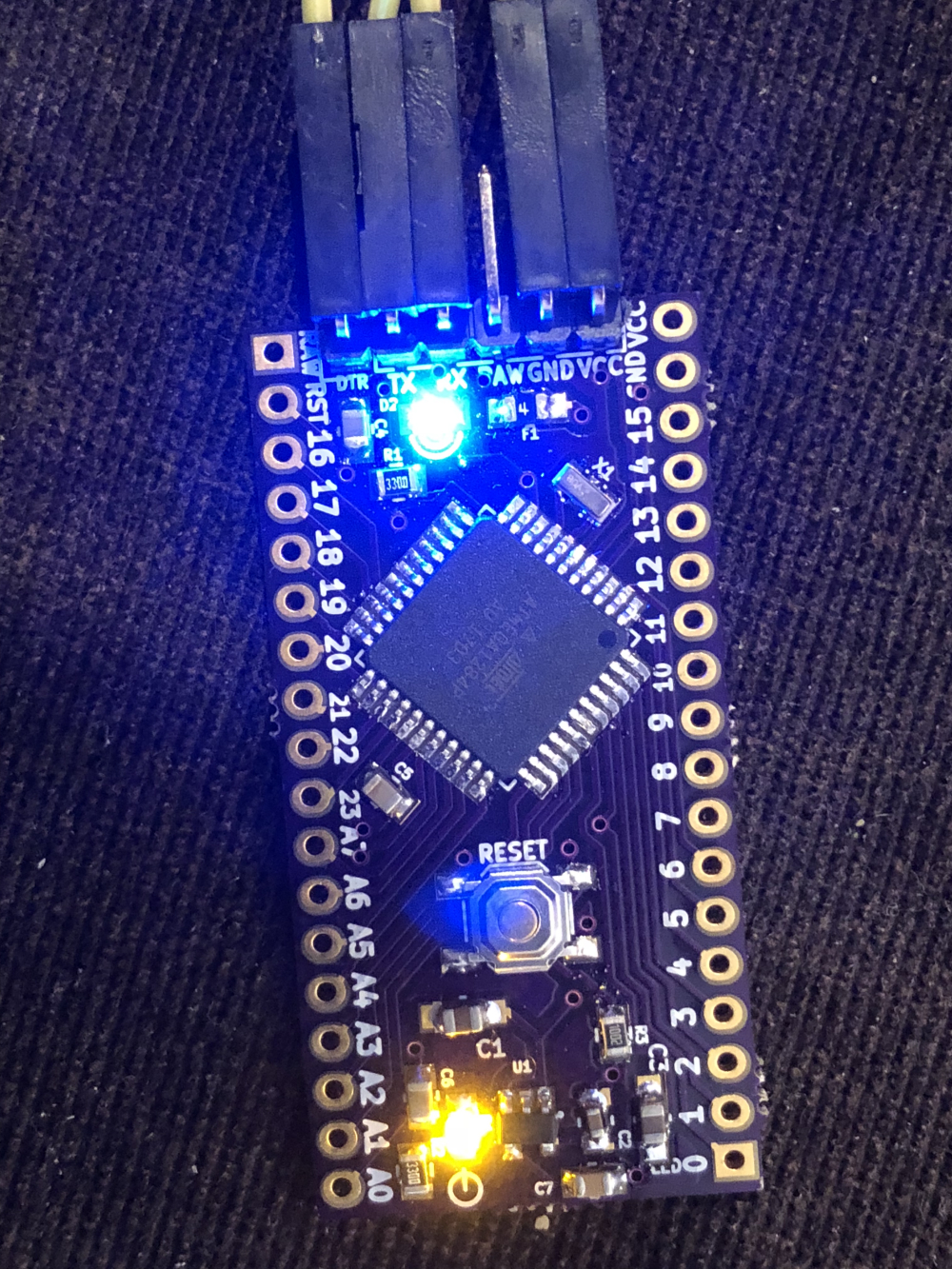
My new toy (atmega1284p) - Mightyduino
However, I have to think about connecting radio as this is just a bare board.
Size wise it is quite small -
RE: What did you build today (Pictures) ?
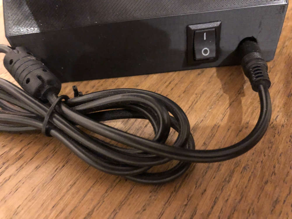
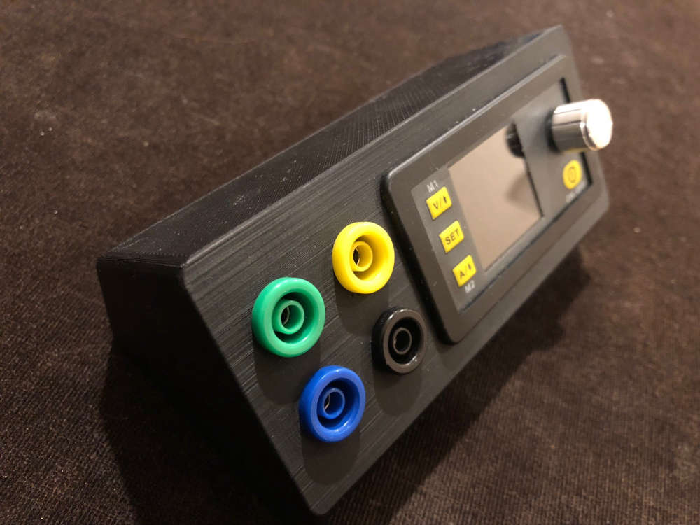
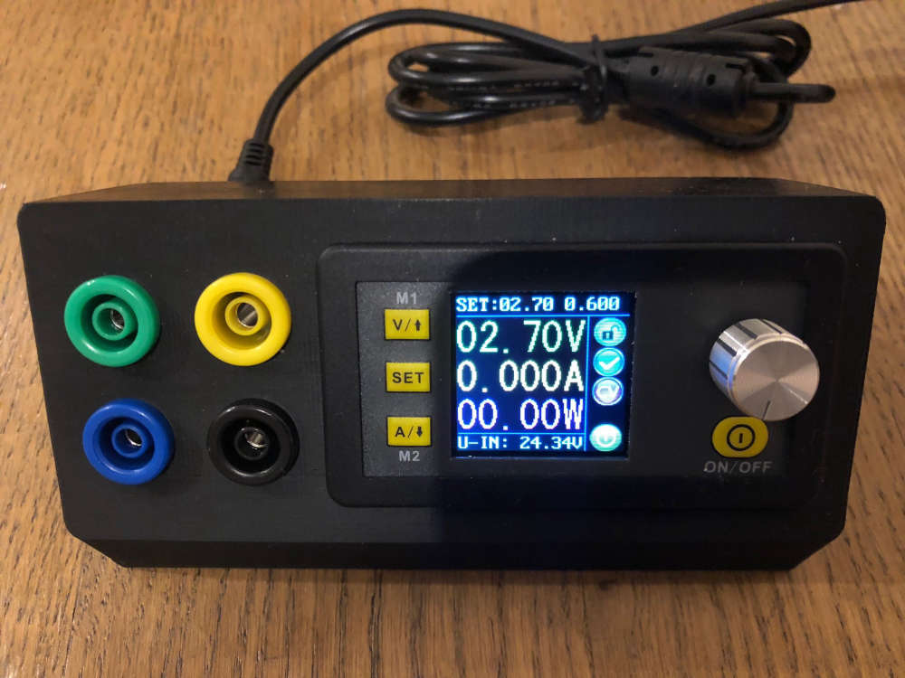
This is my new PSU - 3D printed enclosure and a few components
It is very precise. -
RE: 💬 Various bootloader files based on Optiboot 6.2
@mar.conte yes, you can measure consumption (should be in uA) while sleeping with a good voltmeter.
However, I really fail to understand what has Nick's sketch you mentioned to do with MySensors? I suppose some people here may be aware of sleeping issues, but again your problem has nothing to do with MySensors.
Please see the following - it may help you troubleshoot your issue
https://www.mysensors.org/build/battery -
RE: [solved] Sensor freezes - Low memory available, stability problems may occur.
@scalz I'm with you, but just like you I just do not have time for it. There is Teensy 3.2 with excellent footprint and 10 times speed and memory. So I just feel like if I'm going to spend time, it has to be not yesterday's technology.
-
RE: Which dust sensor do you use and why?
@vladimir The answer is it depends. If you are happy with +/- 40% error, you probably be better of with a generic dust sensor. I think the best would be if you do a bit of research online. This is would be a good start - http://aqicn.org/sensor/
Personally, I moved from a cheap sensor to Plantower PMS7003 (about $23). The amount of time one spends in calibrating and understanding cheap sensors, is just not worth it in my view.
-
RE: Scene Controller
This is a semi finished project. The power is fed via ICSP through 662k (under the red tape):
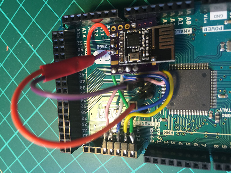
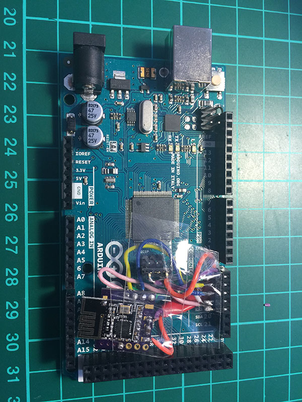
Now I need to isolate everything:
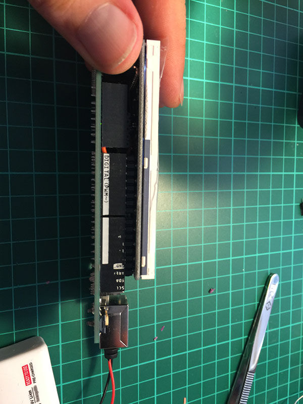
This is how Mega + the screen looks:
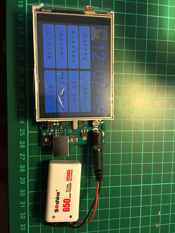
Now I need to figure out how to stick the battery between the screen and Mega
Any suggestions welcome! -
RE: 💬 MyMultisensors
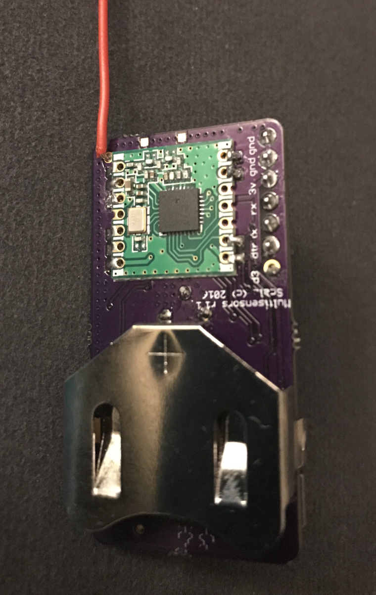
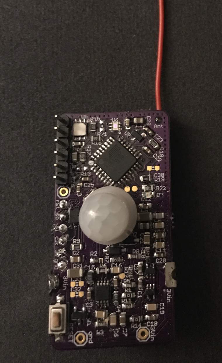
My sensor is now fully completed with all sensors and flash. I decided to go for 2450 battery
-
RE: Issues with NACK on RFM69HW
@ryanmt can you please try to use any AVR instead of Wemos for the GW?
Are you 100% sure you have HW version?Try with and without
define MY_IS_RFM69HW
-
RE: Sketch for Lightning Sensor
I have adopted the MOD-1016 module (https://www.embeddedadventures.com/datasheets/MOD-1016_hw_v8_doc_v4.pdf) for MySensors if anyone is interested:
/* Copyright (c) 2016, Embedded Adventures All rights reserved. Contact us at source [at] embeddedadventures.com www.embeddedadventures.com Redistribution and use in source and binary forms, with or without modification, are permitted provided that the following conditions are met: - Redistributions of source code must retain the above copyright notice, this list of conditions and the following disclaimer. - Redistributions in binary form must reproduce the above copyright notice, this list of conditions and the following disclaimer in the documentation and/or other materials provided with the distribution. - Neither the name of Embedded Adventures nor the names of its contributors may be used to endorse or promote products derived from this software without specific prior written permission. THIS SOFTWARE IS PROVIDED BY THE COPYRIGHT HOLDERS AND CONTRIBUTORS "AS IS" AND ANY EXPRESS OR IMPLIED WARRANTIES, INCLUDING, BUT NOT LIMITED TO, THE IMPLIED WARRANTIES OF MERCHANTABILITY AND FITNESS FOR A PARTICULAR PURPOSE ARE DISCLAIMED. IN NO EVENT SHALL THE COPYRIGHT HOLDER OR CONTRIBUTORS BE LIABLE FOR ANY DIRECT, INDIRECT, INCIDENTAL, SPECIAL, EXEMPLARY, OR CONSEQUENTIAL DAMAGES (INCLUDING, BUT NOT LIMITED TO, PROCUREMENT OF SUBSTITUTE GOODS OR SERVICES; LOSS OF USE, DATA, OR PROFITS; OR BUSINESS INTERRUPTION) HOWEVER CAUSED AND ON ANY THEORY OF LIABILITY, WHETHER IN CONTRACT, STRICT LIABILITY, OR TORT (INCLUDING NEGLIGENCE OR OTHERWISE) ARISING IN ANY WAY OUT OF THE USE OF THIS SOFTWARE, EVEN IF ADVISED OF THE POSSIBILITY OF SUCH DAMAGE. */ // Enable debug prints to serial monitor #define MY_DEBUG // Enable and select radio type attached #define MY_RADIO_NRF24 //#define MY_RADIO_RFM69 #define MY_NODE_ID 15 #include <Wire.h> #include <MySensors.h> #include <AS3935.h> // AS3935 MOD-1016 by Embedded Adventures volatile bool detected = false; //-----------------IMPORTANT-------------------- //---------------CHANGE SETTINGS HERE----------- #define IRQ_pin 2 #define AS3935_TUNE_CAPS 6 // <-- SET THIS VALUE TO THE NUMBER LISTED ON YOUR BOARD #define AS3935_INDOORS 1 // AS3935_INDOORS=1 indoors, AS3935_INDOORS=0 outdoors #define AS3935_NOISE_FLOOR 6 #define AS3935_ENABLE_DISTURBERS 1 // 0 or 1 #define CHILD_ID_DISTANCE 1 #define CHILD_ID_INTENSITY 2 MyMessage msgDist(CHILD_ID_DISTANCE, V_DISTANCE); MyMessage msgInt(CHILD_ID_INTENSITY, V_VAR1); void setup() { Serial.begin(115200); while (!Serial) {} Serial.println("MOD-1016 (AS3935) Lightning Sensor"); Serial.println("beginning boot procedure...."); Wire.begin(); mod1016.init(IRQ_pin); //-----------------IMPORTANT-------------------- //---------------CHANGE SETTINGS HERE----------- //Tune Caps, Set AFE, Set Noise Floor //autoTuneCaps(IRQ_pin); mod1016.setTuneCaps(AS3935_TUNE_CAPS); delay(2); #if AS3935_INDOORS == 1 mod1016.setIndoors(); #else mod1016.setOutdoors(); #endif delay(2); mod1016.setNoiseFloor(AS3935_NOISE_FLOOR); delay(2); #if AS3935_ENABLE_DISTURBERS == 1 mod1016.enableDisturbers(); #else mod1016.disableDisturbers(); #endif //mod1016.calibrateRCO(); delay(2); Serial.println("TUNE\tIN/OUT\tNOISEFLOOR"); Serial.print(mod1016.getTuneCaps(), HEX); Serial.print("\t"); Serial.print(mod1016.getAFE(), BIN); Serial.print("\t"); Serial.println(mod1016.getNoiseFloor(), HEX); Serial.print("\n"); pinMode(IRQ_pin, INPUT); attachInterrupt(digitalPinToInterrupt(IRQ_pin), alert, RISING); Serial.println("after interrupt"); // delay execution to allow chip to stabilize. delay(1000); } void presentation() { // Send the sketch version information to the gateway and Controller sendSketchInfo("Lightning Sensor MOD-1016", "1.0"); // Register all sensors to gw (they will be created as child devices) present(CHILD_ID_DISTANCE, S_DISTANCE); present(CHILD_ID_INTENSITY, S_CUSTOM); } void loop() { if (detected) { translateIRQ(mod1016.getIRQ()); detected = false; } } void alert() { detected = true; } void translateIRQ(uns8 irq) { switch(irq) { case 1: Serial.println("Noise detected"); break; case 4: Serial.println("Disturber detected"); break; case 8: Serial.println("Lightning detected!"); printandsendToGW(); break; } } void printandsendToGW() { int distance = mod1016.calculateDistance(); unsigned int lightning_intensity = mod1016.getIntensity(); if (distance == -1) Serial.println("Lightning out of range"); else if (distance == 1) Serial.println("Distance not in table"); else if (distance == 0) Serial.println("Lightning overhead"); else { Serial.print("Lightning ~"); Serial.print(distance); Serial.println("km away\n"); Serial.print("Lightning Intensity: "); Serial.println(lightning_intensity); send(msgDist.set(distance)); send(msgInt.set(lightning_intensity)); } }
You have to change the sketch according to your module settings
-
RE: atmega328p-au counterfeit
@yveaux Yes, the problem has gone as soon as the new chip was soldered and the firmware burned. A lot of valuable time wasted and a lesson learnt - no more Aliexpress for components. Only a reliable source - Digi-key, mouser, allow, Farnell etc.
-
RE: nrf24l01+ RPi2 direct connection problem
@salvato Thanks very much!
The makefile has to be changed toThis is for the standard PI
amend the following:
#define BCM2835_PERI_BASE 0x3F000000I can confirm - now it works and everything compiles fine!
-
RE: Basement Monitor
I hate to disappoint you @micah but @Mike-Musskopf has got a point:
-
MQ* sensors are power hungry. You may want to connect everything up to 240V via a small PSU. There is a big thread on mysensors about air quality detection.
-
DHT is not the best sensor for a battery application. Please check BME280 (pressure, temp and hum) or Si7021 (temp and hum) - these would be my favourite sensors for low power consumption.
Small tip - your Arduino Pros must be 3.3V and not 5V for the battery usage.
-
-
RE: Battery Attiny85 Door/Window wireless Sensor
Did you try changing nrf24l01+? There is a problem with a few fake ones
-
RE: NRF24l01+ vs. NRF24l01+ pa + lna
I just tried the ugly fix by @Oitzu on my GW and now I can confirm that the reception 3 walls away is much more stable. Generally speakIng my scene controller has been working intermittently and it is super stable now. My advice is as follows:
-
read the feedback on Alixexpress and order nrf24l01+ + PA from a reputable name. Personally I had to go through several modules.
-
Feed it from Arduino 5V pin via AMS1117.
This makes sure the feed is 3.3V solid. You may need to use LC filter to get the ripple out if you have a bad clone or a noisy feed -
make sure you solder a cap - 4.7uF or higher.
-
there are settings in MyConfig.h:
RF24_PA_LEVEL_GW
Which you may need to change.
-
Try to scan 2.4Ghz and change the channel accordingly
-
if nothing helps please re-do the steps above. Please note that some Arduino clones are terrible quality. This may have some contribution towards your issue.
-
-
RE: Ethernet vs Serial gateway performance.
@Kristiaan-Nugteren said:
So what kind of updates do these gateways get? Are these needed to improve stability and security?
No, this is just MySensors protocol version.
As @mfalkvidd said If there are upgrades to the MySensors protocol, the gateway may or may not need to be upgraded. -
RE: Scene Controller
Additionally, I have recently received a new Enhanced Nextion screen (again from Itead Studio) and a new ESP8266 PCB:
Much thinner so watch this space....
-
RE: sensors stop working after time
@Reza I have similar problem with a few sensors and I suspect it must be the code. They freeze after quite a few days
-
RE: Domoticz V_TEXT sensor now bidirectional
@sushukka finally! thanks for letting us know
-
RE: My own board (50mm x 30mm)
@rmtucker I'm using rfm69w with @GertSanders board (I think it is v1-1) via the same adapter you ordered. You need to solder IRQ pad in order for the board to work with rfm69. I tried to compile both a gateway and a sensor code and it worked. No need to have a crystal if you have the right bootloader on atmega328p. With or without crystal does not matter for radio. Radio has got its own crystal
-
RE: Scene Controller
@scalz I am not that smart yet to design my own boards. Having said that I have made a good progress on C++ and MySensors over a year. So designing my own PCB is a next logical step.
The problem is that my home has been fully automated. I have to challenge myself with a more difficult projects or move on to automate my neighbours house lol
The most difficult part though is finding the right case. Printing on 3D printer is not cheap as I do not have one and finding something of the shelf is literally impossible.Talking about the PCB, I took the one design by
Peter and Aidan:http://tech.scargill.net/new-pcb/
However, I'm redesigning the software part to make it a multi functioning scene controller for Domoticz.
-
RE: sensors stop working after time
@scalz I suspect that it happens during a sleep mode. I do not have the same problem with those nodes which do not go to sleep (powered from 240V). For example, my pulse meter node never froze.
Unfortunately, I never had time to go into details as to why this is happening. It could be related to hardware or power source unfortunately too. -
RE: Sensebender Micro
@stefaanv well, that's the problem - you must install Sensebender Micro (or I think you can use Arduino Pro Mini 3.3V) board. You MUST NOT provide more than 3.3V otherwise you may damage the board or radio. Please double check
Please refer to this link below to install the correct board in Arduino:
-
RE: Bosch BME680 Sensor
@heinz said in Bosch BME680 Sensor:
@alexsh1
No I am not using the BSEC library. I read the raw values of the resistance and calculate the first derivative for triggering the ventilation system. The ventilation system is turned on, when
(delta resistance)/minute > thresholdSometimes the ventilation is also triggered when I open my fridge. Then the smell of food coming out of the fridge also fires the trigger.
It is said that the sensor is very sensitive to any kind of silicone which is basically everywhere in the air wVErhen you have dishes created from silicone in your kitchen. Silicone poisens/blinds the sensor immediately for several hours.
So be careful when making experiments with it.OK, so you are using the first derivative (rate of change/time). Clear
This is amazing - it triggered when one opens the fridge? Must be very sensitive.Ok, let me tinker with the sensor and I'll post my feedback here.
-
RE: Cobine working DHT22 and LDR with a RelayWithButtonActuator
@Dick With sketches it is like this sometimes - troubleshooting is time consuming.
I would suggest the following. Try to comment out line by line on the LDR code, upload and see if it works. Try to insert as many Serial.print as you could to print the status of variables to the serial port.I do not have the LDR so cannot help you much on this one. I have multiple other sketches combined together working just fine.
-
RE: Motion Sensor debounce
I think the final product would be looking like this:
#define DUPLICATE_INTERVAL 30000 ..................... if (sleep(digitalPinToInterrupt(MOTION_INPUT_PIN), CHANGE, SLEEP_TIME)) { motionDetected = true; motionTrips++; sleep(DUPLICATE_INTERVAL); }
Testing now
-
RE: 💬 Building a Raspberry Pi Gateway
@nico you need a sensor to send data to GW and assuming you have GW added to Domoticz, Domoticz will add up corresponding values to "Devices"
-
RE: Bosch BME680 Sensor
@neverdie this is my observation as well that the sensor is showing strange values in the beginning but gradually they become more and more accurate. I have not tinkered long enough to have good viable results.
-
RE: [security] Introducing signing support to MySensors
@Anticimex I must admit that signing is working really-really nicely on my custom made nodes (Soft sign and ATSHA204A)
Apart from a small issue with the sensebender, which I believe is not a signing issue, it is working like a charm. All credit to you! Thank you
Starting sensor (RNNNAS, 2.0.0-beta) Radio init successful. HTU21D Sensor1.1 - Online! isMetric: 1 TempDiff :1098.00 HumDiff :136.75 T: 998.00 H: 36.75 send: 5-5-0-0 s=0,c=1,t=0,pt=7,l=5,sg=0,st=ok:998.0 send: 5-5-0-0 s=1,c=1,t=1,pt=7,l=5,sg=0,st=ok:36.7 send: 5-5-0-0 s=2,c=1,t=38,pt=7,l=5,sg=0,st=ok:3.29 send: 5-5-0-0 s=255,c=3,t=0,pt=1,l=1,sg=0,st=ok:106 Signing required send: 5-5-0-0 s=255,c=3,t=15,pt=0,l=2,sg=0,st=ok: Waiting for GW to send signing preferences... Skipping security for command 3 type 15 read: 0-0-5 s=255,c=3,t=15,pt=0,l=2,sg=0: Mark node 0 as one that do not require signed messages Mark node 0 as one that do not require whitelisting send: 5-5-0-0 s=255,c=0,t=17,pt=0,l=10,sg=0,st=ok:2.0.0-beta send: 5-5-0-0 s=255,c=3,t=6,pt=1,l=1,sg=0,st=ok:0 Skipping security for command 3 type 16 read: 0-0-5 s=255,c=3,t=16,pt=0,l=0,sg=0: Signing backend: ATSHA204Soft SHA256: 2C4A871ACCAE26760F41E547DD39B7B816FE22EEBCD8DFA2FE00000000000000 Transmittng nonce send: 5-5-0-0 s=255,c=3,t=17,pt=6,l=25,sg=0,st=ok:2C4A871ACCAE26760F41E547DD39B7B816FE22EEBCD8DFA2FE Signature in message: 01C31110DAE29D5DCD3771F68B6F29B5CCCF43A3D5397CC8 Message to process: 00050E0306FF4D Current nonce: 2C4A871ACCAE26760F41E547DD39B7B816FE22EEBCD8DFA2FEAAAAAAAAAAAAAA HMAC: 0CC31110DAE29D5DCD3771F68B6F29B5CCCF43A3D5397CC89A82A89D87E931B8 Signature OK read: 0-0-5 s=255,c=3,t=6,pt=0,l=1,sg=0:M send: 5-5-0-0 s=255,c=3,t=11,pt=0,l=24,sg=0,st=ok:Temp/Hum Sensor - HTU21D send: 5-5-0-0 s=255,c=3,t=12,pt=0,l=3,sg=0,st=ok:1.1 send: 5-5-0-0 s=0,c=0,t=6,pt=0,l=0,sg=0,st=ok: send: 5-5-0-0 s=1,c=0,t=7,pt=0,l=0,sg=0,st=ok: send: 5-5-0-0 s=2,c=0,t=13,pt=0,l=0,sg=0,st=ok: Init complete, id=5, parent=0, distance=1 TempDiff :971.94 HumDiff :0.02 T: 26.06 H: 36.72 send: 5-5-0-0 s=0,c=1,t=0,pt=7,l=5,sg=0,st=ok:26.1 send: 5-5-0-0 s=1,c=1,t=1,pt=7,l=5,sg=0,st=ok:36.7
-
RE: Signing ATSHA Key?
After you generated the keys and did your first node, do the following for soft signing:
Enable USE_SOFT_SIGNING
Enable LOCK_CONFIGURATION
Enable STORE_SOFT_KEY - must be the same
Enable STORE_SOFT_SERIAL - must be individual for each node/GW
Enable STORE_AES_KEY - must be the sameBelow the options above you have to insert your keys.
EDIT: just corrected what you should enable
-
RE: PCB and 3D print companies
@mfalkvidd I use 3D hubs regularly - excellent service and one had got a choice
-
RE: 💬 Building a Raspberry Pi Gateway
@nico I would suggest you open up a different post in the Troubleshooting section regarding this matter
1 post GW and sensor logs
2. How do you know that the GW was added to Domoticz? Logs please? -
RE: MySensors Raspberry port suggestions
@emc2 No, this is not a typo. This is a format. And yes, I have tried it with dots (127.0.0.1) - it did not compile.
-
RE: [solved] !TSM:FPAR:NO REPLY if using #define MY_RFM69_NEW_DRIVER
Solved! The GW radio turned down to be non-H so I have to remove #define MY_IS_RFM69HW to work fine. In case of the old driver, GW and the sensor were tested on the same laptop, i.e. close to each other and hence they worked even with MY_IS_RFM69HW option.
-
RE: Raspberry Pi 3 with 64-bit quad-core SoC, built-in Wi-Fi and Bluetooth announced for $35
@Igor-Katkov said:
Is there any use for all this CPU power in home automation scope?
I struggle to find any use for them.Yes -> compiling is going to be faster!!!
Seriously though my Raspberry currently looks very messyAt least Wifi and Bluetooth are built-in - just need to sort out three transceivers and I am good
-
RE: Use of BH1750 light sensor in low power node
You can measure voltage and see if it drops too much during sending. Unfortunately, CR2032 is not a very powerful power source.
Another idea would bee having sensor measurements done desperately. I have several sensors (BH1750 + TSL2561 + VEML6070 UV(coming shortly) MOD-1016 (lightning sensor)) running from a tiny Li-on 3.7v 350mA battery without any issues. -
RE: BH1750 library hangs
@joão-gouveia A good a reliable power source is a key unless you what to spend hours troubleshooting. Yes, FTDI could be the reason when used as a power source.
Another thing to try is to load an example sketch for BH1750, disconnect the FTDI adapter and use 2xAA batteries to power up your schematic. Then you can check your controller for a log. Unfortunately, you cannot check the log on the node.
-
RE: MH-Z14A CO2 sensor
OK, I manage to get it resolved now. Simple code really - I am going to convert it into MySensors now. One thing to note - there is an error in the formula. This is 5000ppm sensor, therefore "5000" multiplier has to be used in the formula.
// set pin number: const int sensorPin = 2; // the number of the sensor pin long ppm=0; unsigned long duration; void setup() { Serial.begin(9600); // initialize the sensor pin as an input pinMode(sensorPin, INPUT); } void loop(){ duration = pulseIn(sensorPin,HIGH,2000000); ppm = 5000 * (((duration)/1000)-2)/1000; Serial.println("CO2 = " + String(ppm) + " ppm"); delay(10000); }
-
RE: MoteinoMEGA on 2.0.1 error compiling
@hek I can confirm that v.2.1.1 compiles for Moteino Mega. Will update the software on my Mega shortly.
-
RE: Mysensors PH
@szybki946 said in Mysensors PH:
how to fix this error
Effectively you are asking somebody to complete this project for you - this is not just one simple correction. There were a few PH prob projects in the past (just use search), but you have to be careful and maybe need to convert the code from 1.5 to 2.xx. This is not difficult and there is a sticky post how to do that.
-
RE: MH-Z14A CO2 sensor
@epierre In this case you should use 5000 multiplier - please see above my sketch.
There is a mistake in the datasheet file - it has been written for 2000ppm model.Mine has got 20+ pins and it is 0-5000ppm
-
RE: [security] Introducing signing support to MySensors
@Anticimex It seems to me that 90% of all issues is actually RF.
Very annoying!Thanks for your help!
-
RE: Battery issue with whispernode
@cgeo there is no need to check temperature every minute. Many plug and play devices measuring temperature have a sleep time of 10-15mins. Unless you are doing some research that requires one minute readings, I do not see a reason why you need such frequent measurements.
Needless to say that it has a negative effect on the battery life -
RE: Air Quality Sensor
@moskovskiy82 For a fire smoke, you can use pretty much any gas or particle sensor - there are a quite few gases formed during the burning process. MQ2 is highly sensitivity and has a fast response time. I can recommend it for a fire detection usage. However, I have been disappointed in MQ* sensors in general - there are not accurate, require 24h heat-up time, consume a lot of power etc. The only advantage is the price.
To detect fire to can use a flame sensor - http://www.instructables.com/id/Flame-detection-using-Arduino-and-flame-sensor/
-
RE: Async sensor Libraries (SI7021, APDS-9306)
@scalz You could share your code too
-
RE: Singing 2.2.0
@anticimex My bad - you have actually said it at the top "This is because in 2.2, a checksum has been added to the security data in EEPROM to avoid usage of tampered or accidentally wiped data."
:(((
I need to get my reading glasses
Sorry -
RE: Safe In-Wall AC to DC Transformers??
@Samuel235 it is subjective. 300mA slow blow fuse will not cut it off if the current is 300mA or slightly above for a short time whereas the fast blow fuse will (at the higher current though in our example as you do not want to burn the fuse due to a spike). Unless you have a very sensitive electronics, in my experience both fuses would provide you adequate protection. In some cases (engines), you have to use a slow blow fuse as the start up current may blow the fuse.
Personally, I'm very much in favour of the fast blow fuse in this setup
-
RE: The dust sensor is now finally working
@neverdie No, you cannot. I looked into this a year ago as I do have allergy as well.
Unfortunately, without a specific equipment not much can be done. -
RE: Multiple BME280 sensor for Domoticz
@palmerfarmer said in Multiple BME280 sensor for Domoticz:
Hi,
I'm trying to build a node that uses x2 BME280 sensors for a whole house fan controller, one inside temp/hum and one outside. The BME280 has a selectable I2C address by grounding the SDO pin on the sensor. I have successfully tested this using the BlueDot_BME280.h library and sketches.
Problem I am having is turning this sketch into a working Mysensors node I can use in domoticz. I think I'm almost there but cannot see why i am getting an 'invalid use of non-static member function' message.
here is my hacked code...I thought i would try and get it working with one BME280 first..
Check if you use } or { correctly.
I can see one mistake:else
{
Serial.print(F("Temperature in Celsius from Sensor 1:\t\t"));
Serial.println(F("Null"));
Serial.print(F("Humidity in % from Sensor 1:\t\t\t"));
Serial.println(F("Null"));
Serial.print(F("Pressure in hPa from Sensor 1:\t\t\t"));
Serial.println(F("Null"));
{ (This should be } ) -
RE: Air Quality Sensor
@rollercontainer I followed David Gironi method to calibrate - it is described as follows:
Before you can use the sensor, it has to be calibrated. For this, connect the sensor to your circuit and leave it powered on for 12-24 h to burn it in. Then put it into outside air, preferably at 20°C/35% rel. hum. (humidity is not so crucial). Read out the calibration value as such
float rzero = gasSensor.getRZero();
Wait until the value has somewhat settled (30min-1h). Remember, this is an ADC measurement so you might not want to wait some time between reading the sensor and also do some averaging. Once you have determined your RZero, put it into the MQ135.h. Note: Different sensors will likely have different RZero!#define RZERO 76.63
Congrats, you have calibrated the sensor and can now read the CO2 ppm value in your sketch
float ppm = gasSensor.getPPM();
-
RE: The dust sensor is now finally working
@NeverDie Please see this thread re pollen count:
https://forum.mysensors.org/topic/3603/pollen-sensor-for-hay-fever-alert/6
I did not realise, but it has been two years now since I looked into this....
-
RE: UPS
I'm using on of these
http://www.pimodulescart.com/shop/
I have LiFePO4 4000mAh battery pack - this is enough to weather the longest power outage
-
RE: Smallest possible GW
@Samuel235 my two pennies' worth...probably it's not worth upgrading, but I liked the Bluetooth module and not going to use the wifi. Additionally, all libraries are going to be updated for rpi3 so eventually you will have to upgrade. Compiling is WAY much faster. At £25 this not a huge decision. I have many scripts in Domoticz and sometimes the web-interface is slowing down and even freezing so I'm hoping this will be gone on RPi3
-
RE: Improvement Xiaomi smart kettle (I need help!)
@vladimir I do not understand the purpose of switch a kittle remotely. If there is no water, what would you do?
Additionally, I think you'd find very little in internet on your topic. It required hacking into existing Xiaomi electronics. If you want to do that, you need to dismantle the kettle and reverse engineer it.
-
RE: Next generation dust sensor for MySensors
@gohan This is hard to say. Every sensor has got its pros and cons. You may be happy with $2-3 sensor or need a more precision sensor for $25. It depends.
I would say that PMS7003 is very advanced and precise enough. However, this is my subjective opinion.
-
RE: Battery based atmega328p sensor (no SMD)
@GertSanders said:
@alexsh1 said:
26650
Fully charged these batteries are 4.2V, which is too high for the radio. In terms of cost, they require a special Li-Ion battery loader. Cutout voltage is aroud 2.5V. Capacity wise they would allow a node to work 3 years. Personally I'm happy with something over 1 year at 10th of the cost.
Well, not exactly. Have a look here: http://forum.mysensors.org/topic/3309/powering-nodes-3-3v-with-18650-26650/7
The cost of LDO is about Eur 1 for 20 pieces including shipping from HK
No charger is needed (and I have one away) -> TP4056 with Battery protection is the answer. Just plug it into the USB to charge. The cost is Eur 2-3. The only cost here is battery itself. With PCB it is around Eur 10 vs 2xAA (or 2xAAA), which is what? Eur 4-5? Fine, but this is rechargeable and you can use it in other projects. -
RE: Ceech-Board Buyers
What the point of such a complaint in the hardware section about one of the best sellers providing an excellent support I personally have come across???
-
RE: Fewer home automation postings? What's behind it?
Just my 2 cents
What @NeverDie is saying is true - it may be seasonal or just a decline trend very hard to say.
I do see this across all HA forums.
Firstly, a normal temp/hum node is not exciting any more - it has to be more intellegent. Like Alexa, please tell me ...
Another thing is that generally with social media development, I did notice a lot of forums activity has declined or simply stopped.Let’s not forget that there are many plug and plug HA solutions and DIY may not appeal to all people
-
RE: 💬 Various bootloader files based on Optiboot 6.2
@GertSanders OK, I sorted it out.
I had to create "BlueBoard" and "standard" under "variants" and copy two corresponding files pins_arduino.h
At least I can compile now.Will try to upload a sketch later on and see if it works.
-
RE: 2.4" TFT: does it work with MySensors?
@the-cosmic-gate First things first. You need to sort out the problem with touch. Basically, you need to load the 'paint' sketch and be able to draw or paint on your screen. If it does not work, there is no point moving to softSPI/MySensors as you won't have a working scene controller (touch is important). Additionally, I'd suggest you try to stick to UTFT library.
You may spend a lot of time on this as these cheap screens normally have zero documentation. You can contact the seller and ask about schematic - this would help you to identify pinout. My first cheap TFT screen had pins A2-A6 used for touch if I remember correctly
-
RE: Fewer home automation postings? What's behind it?
@zboblamont Good for you. I still play with these:
-
RE: 💬 Various bootloader files based on Optiboot 6.2
@samuel235 Looks like you are right - without realising I did press update button thinking about a sketch rather than about the update
Corrected this issue aleady in the boards.txt
-
RE: rfm69 network issue
These test sketches work just fine including ACK
Node sketch (rfm69cw)
/* RFM69 library and code by Felix Rusu - felix@lowpowerlab.com // Get libraries at: https://github.com/LowPowerLab/ // Make sure you adjust the settings in the configuration section below !!! // ********************************************************************************** // Copyright Felix Rusu, LowPowerLab.com // Library and code by Felix Rusu - felix@lowpowerlab.com // ********************************************************************************** // License // ********************************************************************************** // This program is free software; you can redistribute it // and/or modify it under the terms of the GNU General // Public License as published by the Free Software // Foundation; either version 3 of the License, or // (at your option) any later version. // // This program is distributed in the hope that it will // be useful, but WITHOUT ANY WARRANTY; without even the // implied warranty of MERCHANTABILITY or FITNESS FOR A // PARTICULAR PURPOSE. See the GNU General Public // License for more details. // // You should have received a copy of the GNU General // Public License along with this program. // If not, see <http://www.gnu.org/licenses></http:>. // // Licence can be viewed at // http://www.gnu.org/licenses/gpl-3.0.txt // // Please maintain this license information along with authorship // and copyright notices in any redistribution of this code // **********************************************************************************/ #include <RFM69.h> //get it here: https://www.github.com/lowpowerlab/rfm69 #include <SPI.h> //********************************************************************************************* // *********** IMPORTANT SETTINGS - YOU MUST CHANGE/ONFIGURE TO FIT YOUR HARDWARE ************* //********************************************************************************************* #define NETWORKID 100 // The same on all nodes that talk to each other #define NODEID 2 // The unique identifier of this node #define RECEIVER 1 // The recipient of packets //Match frequency to the hardware version of the radio on your Feather #define FREQUENCY RF69_433MHZ //#define FREQUENCY RF69_868MHZ //#define FREQUENCY RF69_915MHZ #define ENCRYPTKEY "sampleEncryptKey" //exactly the same 16 characters/bytes on all nodes! #define IS_RFM69HCW false // set to 'true' if you are using an RFM69HCW module //********************************************************************************************* #define SERIAL_BAUD 115200 #define RFM69_CS 10 #define RFM69_IRQ 2 #define RFM69_IRQN 0 // Pin 2 is IRQ 0! #define RFM69_RST 9 #define LED 8 // onboard blinky int16_t packetnum = 0; // packet counter, we increment per xmission RFM69 radio; //RFM69 radio = RFM69(RFM69_CS, RFM69_IRQ, IS_RFM69HCW, RFM69_IRQN); void setup() { while (!Serial); // wait until serial console is open, remove if not tethered to computer Serial.begin(SERIAL_BAUD); Serial.println("Arduino RFM69HCW Transmitter"); // Hard Reset the RFM module pinMode(RFM69_RST, OUTPUT); digitalWrite(RFM69_RST, HIGH); delay(100); digitalWrite(RFM69_RST, LOW); delay(100); // Initialize radio radio.initialize(FREQUENCY,NODEID,NETWORKID); if (IS_RFM69HCW) { radio.setHighPower(); // Only for RFM69HCW & HW! } radio.setPowerLevel(31); // power output ranges from 0 (5dBm) to 31 (20dBm) radio.encrypt(ENCRYPTKEY); pinMode(LED, OUTPUT); Serial.print("\nTransmitting at "); Serial.print(FREQUENCY==RF69_433MHZ ? 433 : FREQUENCY==RF69_868MHZ ? 868 : 915); Serial.println(" MHz"); } void loop() { delay(1000); // Wait 1 second between transmits, could also 'sleep' here! char radiopacket[20] = "Hello World #"; itoa(packetnum++, radiopacket+13, 10); Serial.print("Sending "); Serial.println(radiopacket); if (radio.sendWithRetry(RECEIVER, radiopacket, strlen(radiopacket))) { //target node Id, message as string or byte array, message length Serial.println("OK"); Blink(LED, 50, 3); //blink LED 3 times, 50ms between blinks } radio.receiveDone(); //put radio in RX mode Serial.flush(); //make sure all serial data is clocked out before sleeping the MCU } void Blink(byte PIN, byte DELAY_MS, byte loops) { for (byte i=0; i<loops; i++) { digitalWrite(PIN,HIGH); delay(DELAY_MS); digitalWrite(PIN,LOW); delay(DELAY_MS); } }
Gateway sketch (Moteino Mega, rfm69hcw):
/* RFM69 library and code by Felix Rusu - felix@lowpowerlab.com // Get libraries at: https://github.com/LowPowerLab/ // Make sure you adjust the settings in the configuration section below !!! // ********************************************************************************** // Copyright Felix Rusu, LowPowerLab.com // Library and code by Felix Rusu - felix@lowpowerlab.com // ********************************************************************************** // License // ********************************************************************************** // This program is free software; you can redistribute it // and/or modify it under the terms of the GNU General // Public License as published by the Free Software // Foundation; either version 3 of the License, or // (at your option) any later version. // // This program is distributed in the hope that it will // be useful, but WITHOUT ANY WARRANTY; without even the // implied warranty of MERCHANTABILITY or FITNESS FOR A // PARTICULAR PURPOSE. See the GNU General Public // License for more details. // // You should have received a copy of the GNU General // Public License along with this program. // If not, see <http://www.gnu.org/licenses></http:>. // // Licence can be viewed at // http://www.gnu.org/licenses/gpl-3.0.txt // // Please maintain this license information along with authorship // and copyright notices in any redistribution of this code // **********************************************************************************/ #include <RFM69.h> //get it here: https://www.github.com/lowpowerlab/rfm69 #include <SPI.h> //********************************************************************************************* // *********** IMPORTANT SETTINGS - YOU MUST CHANGE/ONFIGURE TO FIT YOUR HARDWARE ************* //********************************************************************************************* #define NETWORKID 100 //the same on all nodes that talk to each other #define NODEID 1 //Match frequency to the hardware version of the radio on your Feather #define FREQUENCY RF69_433MHZ //#define FREQUENCY RF69_868MHZ //#define FREQUENCY RF69_915MHZ #define ENCRYPTKEY "sampleEncryptKey" //exactly the same 16 characters/bytes on all nodes! #define IS_RFM69HCW true // set to 'true' if you are using an RFM69HCW module //********************************************************************************************* #define SERIAL_BAUD 115200 #define RFM69_CS 10 #define RFM69_IRQ 2 #define RFM69_IRQN 0 // Pin 2 is IRQ 0! #define RFM69_RST 9 #define LED 15 // onboard blinky int16_t packetnum = 0; // packet counter, we increment per xmission RFM69 radio; void setup() { while (!Serial); // wait until serial console is open, remove if not tethered to computer Serial.begin(SERIAL_BAUD); Serial.println("Feather RFM69HCW Receiver"); // Hard Reset the RFM module pinMode(RFM69_RST, OUTPUT); digitalWrite(RFM69_RST, HIGH); delay(100); digitalWrite(RFM69_RST, LOW); delay(100); // Initialize radio radio.initialize(FREQUENCY,NODEID,NETWORKID); if (IS_RFM69HCW) { radio.setHighPower(); // Only for RFM69HCW & HW! } radio.setPowerLevel(31); // power output ranges from 0 (5dBm) to 31 (20dBm) radio.encrypt(ENCRYPTKEY); pinMode(LED, OUTPUT); Serial.print("\nListening at "); Serial.print(FREQUENCY==RF69_433MHZ ? 433 : FREQUENCY==RF69_868MHZ ? 868 : 915); Serial.println(" MHz"); } void loop() { //check if something was received (could be an interrupt from the radio) if (radio.receiveDone()) { //print message received to serial Serial.print('[');Serial.print(radio.SENDERID);Serial.print("] "); Serial.print((char*)radio.DATA); Serial.print(" [RX_RSSI:");Serial.print(radio.RSSI);Serial.print("]"); //check if received message contains Hello World if (strstr((char *)radio.DATA, "Hello World")) { //check if sender wanted an ACK if (radio.ACKRequested()) { radio.sendACK(); Serial.println(" - ACK sent"); } Blink(LED, 40, 3); //blink LED 3 times, 40ms between blinks } } radio.receiveDone(); //put radio in RX mode Serial.flush(); //make sure all serial data is clocked out before sleeping the MCU } void Blink(byte PIN, byte DELAY_MS, byte loops) { for (byte i=0; i<loops; i++) { digitalWrite(PIN,HIGH); delay(DELAY_MS); digitalWrite(PIN,LOW); delay(DELAY_MS); } }
-
RE: Outdoor rust prevention
Recently I had to change batteries in the outdoor Netatmo wind sensor
https://www.amazon.co.uk/dp/B016OHME1A/ref=cm_sw_r_cp_api_i_ivx.AbS3R1HDF
The lower battery compartment was completely flooded and guess what - battery contacts were corroded. This is my solution
There was a small water ingress from the top. I have used hot glue to prevent it in the future. Cleaned the battery contacts with a contact cleaner (it also puts a anticorrorion protective layer on the metal) and that’s it
-
RE: 💬 Easy/Newbie PCB for MySensors
@sundberg84 typically, I try to add the lc-filter to the booster as some of them are very noisy. This is very simple - 3.3µH Axial lead inducter and a large 220µF capacitor (I use the SMD version). This helps to smooth any ripple effect.
-
RE: rfm69 network issue
@scalz Sorted. One radio on the GW is with amplification so I had to add the following to the code:
#define MY_IS_RFM69HW #define MY_RF69_IRQ_PIN 2 // not sure if this line makes any difference
All works perfectly now.
-
USB-C PD PSU
Hello,
I have a USB-C PD 26850mAh power bank, which I used to charge my gadgets. I wanted to use the same power bank to charge my Microsoft laptop, which does not have USB-C PD port . USB-C PD can vary voltage / amperage from 5-20V upto 3A. And laptop must be supplied with 15V. How do I connect the two? Well, that’s the answer
This is a USB-C PD Buddy Sink - a little board with a chip which negotiates a precise voltage / amperage one sets-up. Absolutely brilliant!
Now I can use it to extract any voltage in the region 5-20V for any project.In theory can by mysensorised but I do not see any point in controlling it remotely
-
RE: 💬 Stamp size MySensor node
@AWI I just put a link to an eBay. You put "Keystone 3013" in the search and hit search
-
RE: Adapter for RFM69 on NRF24L01+ pinout-header
@GertSanders The range is BY FAR better. I am getting a very stable signal in the corners where nrf24l01+ has never worked. No more voodoo dancing trying to make nrf24l01+ work!
I have not measured the consumption yet as I would need a proper scope rather than using a multimeter. So I had to rely on this table: -
RE: 💬 Sensebender Gateway
@tbowmo it is already done. Thanks to your link I have now Sensebender Gateway board added.
Waiting for an ethernet board now, it has stuck in the post -
RE: Which are the *best* NRF24L01+ modules?
@parachutesj said:
@doug I did some quick tests and I can confim that the modules work better with less voltage. I made best experience with 2.5-2.6V. However they are still much much worse than all others I have and not worth the hassle IMHO.
How did you decrease the voltage on nrf24l01+ PA? I have a voltage regulator providing 3.3V.
-
RE: USB-C PD PSU
@gohan ok, do you have a phone / laptop charger USB-C PD (Power Deivery)? This is not a typical USB interface. With one PSU, one can charge a phone or a laptop. No need to have several chargers.
My issue is this. I have a laptop, which does not have USB-C interface. I also have a power bank powerful enough to provide 30W USB-C PD charging. I do use it for my mobile phone as well as iPad. Unfortunately, I could not charge my laptop (remember, no USB-C port?) until now. I have got the board (in the photo above). It takes power from USB-C PD and you can select any voltage from 5-20V on the output. I programmed 15V (this is my laptop voltage) and used this cable to charge the laptop.https://www.amazon.co.uk/dp/B01DT9X1LI/ref=cm_sw_r_sms_c_api_i_rBP.AbP80WV49
The same board can be used with USB-C PD charger for any project requiring higher than 5V voltage. You can program any voltage in the region 5-20V.
Some time ago I needed 13V power supply and ended up using 24V one and lowering voltage to 13V. -
RE: 💬 Sensebender Gateway
@tbowmo I can confirm now that everything is working fine after I tested the Sensebender GW with the third (yes, third!!!) shield. Thanks Thomas for your help!
-
RE: Air Quality Sensor
@Thanh-Viet Hello. Yes, I have Plantower G3 on order from Aliexpress and won't be able to test it before September. I think adopting it for MySensors is going to be easy
-
RE: USB-C PD PSU
Yes, you can buy it here
https://www.tindie.com/products/clayghobbs/pd-buddy-sink/
Or order the PCB and do it yourself here
https://oshpark.com/shared_projects/B7h1WKOi
This does require very fine SMD soldering!
-
RE: Air Quality Sensor
@paqor yes, in fact my MQ-135 was so unreliable that I had to move on to a different sensor
-
RE: 5v vs. 3.3v Pro Mini battery powered nodes
@yveaux My suggestion is very simple. If there is a device which consumes more than > 5-50uA sleeping on a battery powered node, it has to be completely disconnected while sleeping. This is where TPL5110 comes in. Obviously if an interrupt is used it does not work
-
RE: 💬 MyMultisensors
@scalz yes, it is oshpark- I usually use them as the quality is exceptional. And typically I only need 3-4 pcbs anyway.
Unfortunately, I do not have oven and do not use smd stencil, which means the process is very long and manual. A lot of hot air fan work under the magnifying glass, but given this is not a board with too many components, it works.You should get some commission from Arrow. I have just placed my order for eeprom and some parts ;))
-
RE: MH-Z14A CO2 sensor
I am glad you work it out yourself
I think when it comes to this sensor everything is well documented or available in the Internet -
RE: What did you build today (Pictures) ?
@yveaux This is simple. The Aliexpress seller sent me these instead of black and red ones. So I have been creative - black and blue is negative and yellow and green is positive. Did not bothered waiting for a few weeks for replacement.
-
RE: 💬 MyMultisensors
@scalz I did manage with 5V. Just de-soldered SI7021 and uploaded DualOptiboot. Other components are 5V tolerant. Having said that, I recall I did upload a different bootloader at 5V to Sensebender Micro (without nrf24l01+) without damaging SI7021.
R22 has to be changed for 330 Ohm as 1.5k was way too dark and not visible. I like bright LEDs you know :-))
-
RE: rfm69 frequency question
I wish I knew about it before as I ordered several Moteinos without radios, which are very cheap in the US, and then ordering 868Mhz radios separately.
Well, well - every day I learn something new -
RE: Sonoff, how it works?
@mhmd I never bothered to discover how original Sonoff firmware works. The whole idea that my home is managed via a remote Chinese server is just not appealing to me.
Plus nobody in the DIY community using a native Sonoff app. The whole idea to buy Sonoff is to hack it.I have several Sonoff relays and I am using ESP Easy (Let's control it) firmware:
-
RE: 💬 MyMultisensors
@Sergio-Rius either you have to use lua or there is a much simpler way to do it in Domoticz. Change type to "motion sensor" and then you have an option "off delay". Setup it to 60 seconds and PIR sensor will be off in 60 seconds. Very useful option and yes it is not enabled by default.
-
RE: How do I setup Raspberry Pi 2 with NRF24L01 as MySensor 2.0 Gateway with MyController as controller
@Christian-Simonsen said:
I have tried the below sketch from this page https://www.mysensors.org/download/sensor_api_20#sensor-nodes
But the sketch do not compile due to non defined NODE_ID. I tried to updated the code by changing NODE_ID to MY_NODE_ID and added a line to #DEFINE MY_NODE_ID 1This is not a default sketch, this is just a template to explain how it works. It won't compile (requires NODE_ID definition etc).
Try this sketch:// Enable debug prints to serial monitor #define MY_DEBUG // Enable and select radio type attached #define MY_NODE_ID 1 #define MY_PARENT_NODE_ID 0 #define MY_PARENT_NODE_IS_STATIC #define MY_RADIO_NRF24 #include <MySensors.h> #define CHILD_ID_LIGHT 0 #define LIGHT_SENSOR_ANALOG_PIN 0 unsigned long SLEEP_TIME = 30000; // Sleep time between reads (in milliseconds) MyMessage msg(CHILD_ID_LIGHT, V_LIGHT_LEVEL); int lastLightLevel; void presentation() { // Send the sketch version information to the gateway and Controller sendSketchInfo("Light Sensor", "1.0"); // Register all sensors to gateway (they will be created as child devices) present(CHILD_ID_LIGHT, S_LIGHT_LEVEL); } void loop() { int16_t lightLevel = (1023-analogRead(LIGHT_SENSOR_ANALOG_PIN))/10.23; Serial.println(lightLevel); if (lightLevel != lastLightLevel) { send(msg.set(lightLevel)); lastLightLevel = lightLevel; } sleep(SLEEP_TIME); }
-
RE: What did you build today (Pictures) ?
@nca78 there many other aspects. I’m using a low temp melting solder paste. I have been using only a top quality (no AliExpress) one from Chipquick. It has to be stored property in the fridge.
Using stencil may help. I’m not using it and have to doze the paste very precisely which is a challenge. This is why my soldering is not 100% consistent, but it works. With 0402 components it is not easy - the pad size is very small.
However, I must admit, 0402 are far too small. In the process, unless your space / lab is very well organised many components are lost. And a good magnifying glass / microscope is a must too. In the future, i’ll try to stick to 0805 or larger - these are a bit larger and more visible.
All in all, this is not as difficult as many people may think. With a little bit of practice, this can be done.
-
RE: 💬 Aeos : a NRF52 versatile, up to 9in1, device
@scalz Thumbs up for a 2450! You have it on your other sensor and I'm using it for PIR is makes sense. 2032 is fine for a long sleeping sensor, but PIR will drain it very quickly.
-
RE: solid sate relay
@parachutesj this is the way SSRs work. I do not think you can test them without a load