Just wanted to share my tonight creation
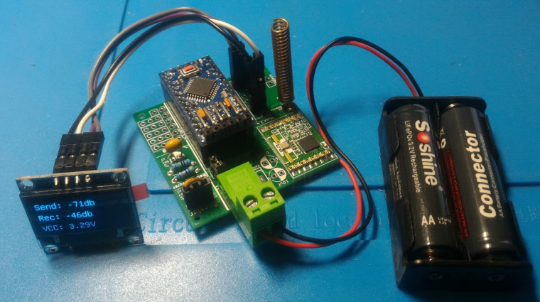
It shows Send and Receive RSSI and vcc (that btw is measured via voltage divider and is spot on with my multimeter)
Posts
-
Portable RFM69 Signal Scanner -
nRF5 action! -
BlackBox: binary, lightweight communication protocol handler source code generator. -
Troubleshooting communication [solved]In fact @sundberg84 usually advices to have the antenna sticking out of the pcb underneath as the ground planes tend to what they are made for: shielding EM. Also trace antenna orientation plays a role too
-
Will MySensors work for me? -
Is there a way to check presence of a MySensors network, and proceed without if not found ? -
Supercap Solar Powered Mysensors nodes as cheap as possibleI am currently testing a couple of concepts to power an outdoor node for temperature and humidity with readily available stuff:
-
2.7v: using this supercap + this module, just hook up any 6v solar panel to Vin and the supercap on the Vout with a diode in between that will block any reverse current and most important will drop voltage by ~0.7v to make it suitable for the supercap. Then I connected a standard EasyPCB from @sundberg84 with standard voltage divider, SHT31 sensor and this booster
-
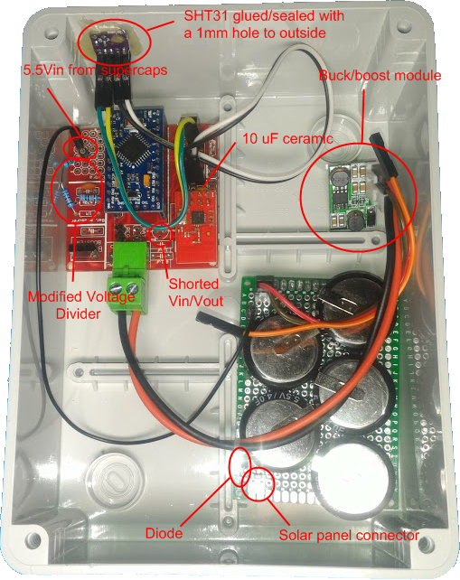
5.5V: using 5 of theese connected directly to 6v solar panel with a diode in between for the above reasons, then connected them to the Vin of the buck-boost module and node connected to the Vout. This time I had to do some changes to EasyPcb: I shorted REG jumper, shorted Vin and Vout on the regulator footprint just above the Arduino and made a different voltage divider on the prototype area with R1 1.22M and R2 300K in order to read a maximum of 5.57v
((1e6+220e3+300e3)/300e3)*1.1 = Vmax = 5.57 Volts
5.57/1023 = Volts per bit = 0.005448028
5.5V inside
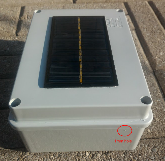
Finished: the solar panel has been glued with transparent silicon for the entire perimeter
-
-
RFM69 antennas comparisonI wanted to share my finding following my RFM69 signal scanner I previously built. I used 2 types of antennas:
-
Hand made like the one mentioned by @sundberg84 in [his project](https://www.openhardware.io/view/389/EasyNewbie-PCB-RFM69-HWW-edition-for-MySensors
I let them run several hours reporting TX power since the new rfm69 driver adjusts power output to the default target RSSI of -80db
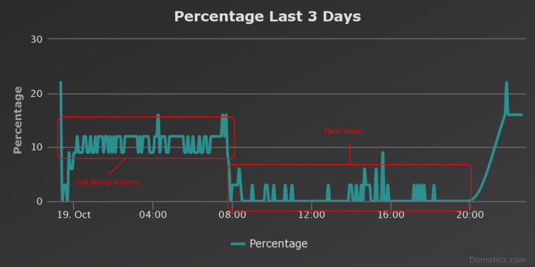
The test was done on the same spot (my desk) and the gw about 5 meters away (1 floor difference, and a couple of walls in between; gw running the coil spring antenna).
I am currently testing the SMA antennas and results are better than the hand made antenna with a TX power of 35/40% instead of 55/60%. My guess is the hand made antenna had to be squeezed inside the box getting a wrong orientation, while the SMA one is outside and it can stay perfectly vertical.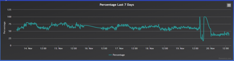
-
💬 Building a Raspberry Pi Gateway -
MQTT IR Remote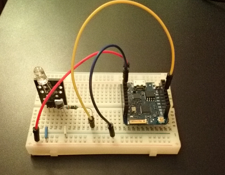
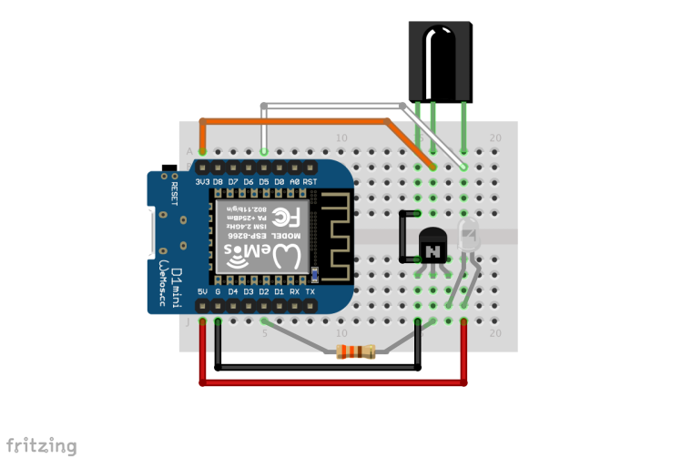
It is actually very simple project: I followed this guide -> http://www.sysrun.io/2017/02/22/use-a-esp8266-to-control-your-ac-via-mqtt/ and used a pn2222a to boost the IR Led like I have seen in this picture
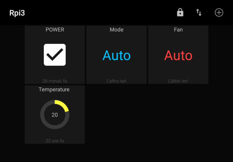
For the control user interface I used MQTT Dash: the app is very simple, just add the appropriate dashboard element to each of the topics.
For MQTT service I used Cloud MQTT and it works perfectly.
This project started as a request from my father to be able to control his Daikin heat pump / AC and since he is not a very computer enthusiast, I had to find something really simple and stand alone without any other additional controllers. The user interface had to be very simple so the only 4 main functions were used, since he was requiring just to be able to switch it on remotely without any time schedule.
Yesterday I did some tests and the communication is really instantaneous. I was a little disappointed as I was able to send commands from the other side of the room only with led pointing a the AC unit (from below the unit it was not a problem at all). Next step would be to open the unit and try to find a 3.3/5V source to power the Wemos and put it inside.Of course the IR library supports other brands and I think it can be converted to mysensors use by replacing the MQTT communication with the usual mysensors functions.
-
Which are trustworthy brands for a simple USB wall charger?It's a compromise between paying premium bucks for a branded charger and having a still tested certified charger still made in China (as per 99% of these kind of products)
-
Things to sell!3 kids are indeed time consuming, but don't sell those yet and use them to teach your kids how to solder and code 😁
-
Ethernet GW vs MQTTFirst you can set username and password, second the gateway is connecting to a broker while ethernet is accepting incoming connections in clear text and no security of any kind ; also if you are accepting connections it is more likely to have a security risk than only outgoing connections
-
USB PowerMeterI'd suggest you to look at Tasker app, otherwise it could get a little complicated and if you aren't very familiar with mains power it's better to stay away from it ☺️
-
help to sketch. motion sensor with ackIf I remember well the send function returns a boolean according to the success of the send. You can check for the result and do a cycle
-
Raspberry Pi SD Card wear out?BTW, I noticed dietpi already has a 460MB tempfs mounted as /tmp so I changed domoticz script to use that for log and it is working
-
Battery status does not show in DomoticzFrom Domoticz forum > if you edit /etc/init.d/domoticz.sh you can do this:
DAEMON_ARGS="-daemon -www 8080 -log /home/pi/log/domoticz.log -loglevel 0"
Just don't forget to put back the original config as the log file would grow quite a lot
-
Powering mote 24/7 using only a supercap and solarHas anyone seen this solution for balancing the supercaps?
https://www.youtube.com/watch?v=rWN7YOuhcO0 -
Do I need to implement the IRQ on future PCBs for nodes?Make a route for irq with a couple of pads that you can bridge them to enable the irq to either d2 or d3 so that you can disable the irq feature in case you need those pins for something else.
-
PIR sensor or kinda?Something like this? https://learn.adafruit.com/adafruit-amg8833-8x8-thermal-camera-sensor/overview