Diode is bad.
You can shorting it.
But then you can power this Arduino only from USB or from +5V in the same time!!!
Not both !!! This can damage your USB port.
Posts made by kimot
-
RE: Killing Nanos, one after the other
-
RE: Temperature serial sketch
@Olaf-Jacobs said in Temperature serial sketch:
First I had 4x DS18B20 temperature sensors hooked up to gpio4 on the pi without the resistor, this worked fine for some time till this gave some issues
Can you write what issues.
Why you connect DS18B20s to RPi without resistor ?
Is it some experiment? -
RE: ๐ฌ Leaky - water detector
@Sixkillers
You can wake up every hour, but hold wifi modem off, increment "wake up counter" and go to deep sleep.
Running time between deep sleeps will be very short
And connect to wifi one per day for example.
And make some tweaks for wifi connection:
For inspiration from Step 6 here:https://www.instructables.com/ESP8266-Pro-Tips/
And final tweak here:
https://www.bakke.online/index.php/2017/06/24/esp8266-wifi-power-reduction-avoiding-network-scan/
-
RE: ๐ฌ Leaky - water detector
@openhardware-io
I think this is not too useful concept.
In circuit diagram, there is no connection GPIO16 to RESET - so no deep sleep mode.
It seems, your node only connect to server when water leaks.
But what after two years, you do not know if battery are still good and your detector alive.
Better way use deep sleep, after some number deep sleep cycles ( one per day? ),
connect to wifi and send battery voltage for example.
If this message is missed, your controller can send you battery replacement message. -
RE: Hi everyone newbish question here
@fdlou147
Ethernet ( with POE ) is very very expensive way to connect your sensors.
Look for prices 24port switches with POE for example.
And 24 nodes is not enough.... -
RE: Modular sketch to be configured with JSON (idea)
Super...
You add software for relay, switch or new temperature sensor through FOTA...
And then go to your node, remove it and connect this devices to it in fact.
No, you really do not need FOTA for this.
But for repairing some bugs in your program yes.
Other case is for example node ID, mqtt topic, some calibrations, offsets, Domoticz sensor IDX etc. -
RE: Trying to develope a whole house energy meter using My Sensors
@PedroHernandez
If you build sensor with ethernet connectivity, simply send your data to Domoticz via http call using Domoticz JSON API. -
RE: ๐ฌ Temperature Sensor
Domoticz globally or only with MySensors ?
My Domoticz is the same version like yours.
Temperatures from ESPeasy are with two decimals on Temperature sensors page, but on devices page only one decimal.
Exactly the opposite like you wrote. -
RE: 2 Arduinos talk to each other over RS485
https://github.com/MajenkoLibraries/ICSC
Examples are there too.
( MySensors uses this code for 485 transport layer too )
Or another very simple example:
-
RE: Laundry sensors
I would simply endured.
Once clean clothes go away and they will go out of the house dirty, smelly or naked...
Then they empty basket sure. -
RE: RPi 3 with Domoticz and RF-link (RFXcom) 'TSP-fail'
@esfnl
You are completely wrong and mix different things together.
Firstly - you wrote RFXcom (with long range antena ) and then mention link to RFLink.
Both devices have got separete device in Domoticz:
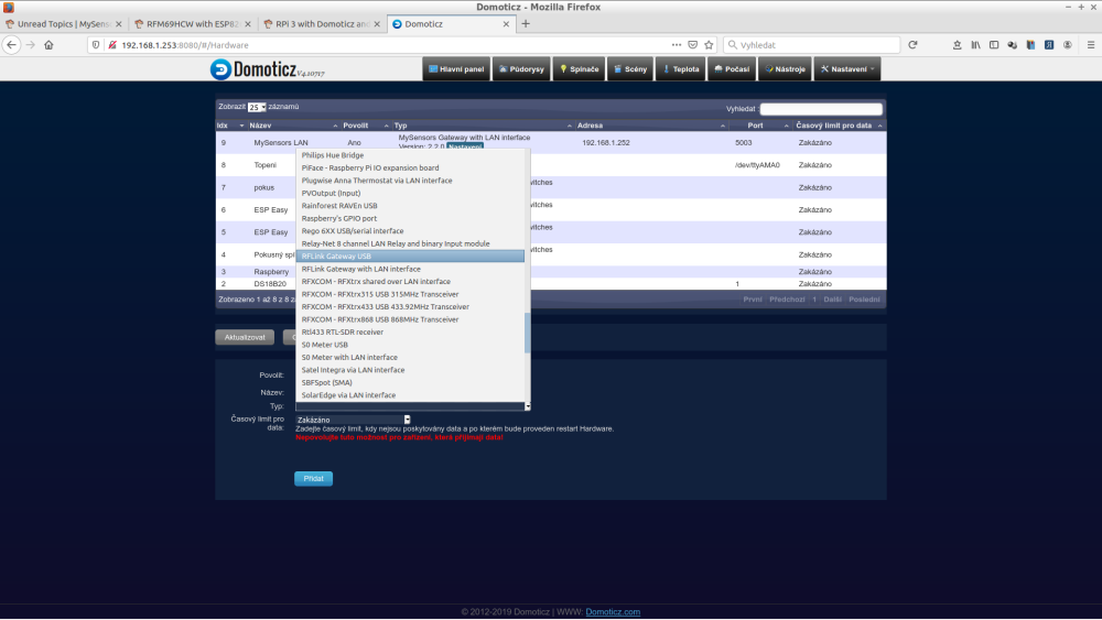
Secondly - RFLink and RFXCom are for intergration most commercial sensors and transducers to 433MHz.
You do not need install MySensors gateway on RPI for use them.
Simply connect them and select in Domoticz devices with appropriate interface.
Then you will see all sensors in your surroundings.
Mostly your neighbors meteostantions, heatpumps etc.
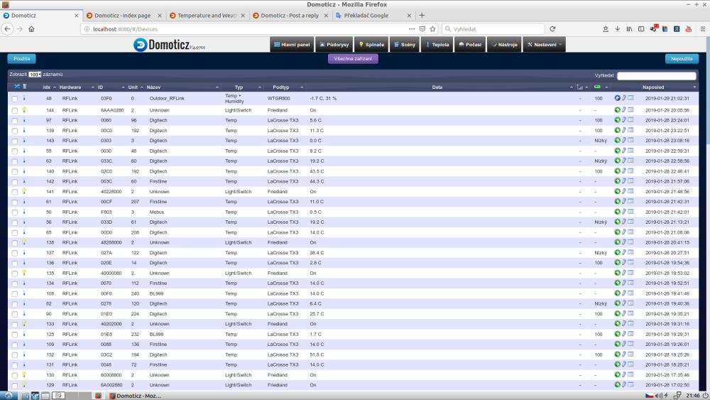
Here is my RFLink sensors list after couple of hours - none from me, all neighbors.
And I live on village ....
No block of flats.
( It is twice as long as you see )
I do not know RFXCom, but RFLink can receive data from MySensors nodes.
According your link, I do not test it.
ONLY receive - so no AUTO ID for nodes, no answer for presentation etc.
If you want use MySensors, I suggest build separate USB gateway and connect it to Domoticz and select
"MySensors Gateway USB" in device list.
That all.
No "./configure" and all this. -
RE: WI-FI IOT modules
@mfalkvidd
Look for ESP-NOW ...
But it is limited to max 20 nodes per one network.
( Without encryption. With encryption, number of nodes is more limited - 6 or 10 ) -
RE: PIR Sensor Gives False High in 55 Minutes (Can't find a way to solve)
Simplify your code maximally.
Remove PIR and UNO and connect D3 and D7 to correct levels.
Remove SoftwareSerial and all SMS function.
Only check serial debug messages for 4-5 hours run.
If it will work, then little by little add other functions.
My tip is problem with combination HW serial and SoftwareSerial. -
RE: is mesh n/w possible using RFM69 without using gateway?
@abt
Look at LowPowerLab RFM69 examples.
In gateway sketch you can see how to handle incoming messages, in others how to send messages.
Combine this two and you obtain node, which is able to send messages to any node and receive messages too.
But it is not realy "mesh" , it is normal "peer to peer" network.
RFM69 has got good range, so in normal house real mesh is not needed, I think.
What I consider real mesh is MySensors with parent nodes or ESP-MESH:https://docs.espressif.com/projects/esp-idf/en/latest/api-guides/mesh.html
-
RE: Sonoff gateway: sketch uploads fine but doesn't run
@user2684
Try:
Install ESPTOOLrun command ( it is for Linux - use com with its number in Windows )
esptool.py --port /dev/ttyUSB0 flash_id
Sonnof must response with its chip ID
Something like this:
Connecting... Manufacturer: e0 Device: 4016
If it does, chip and connection is ok....
-
RE: Multisensor with DSB18B20 and relay
@kvn298
Each sensor must have unique child ID.
Your presentation:
DS18B20 ID=0 to max number of DS18B20
Relay ID=1
So second DS have got the same ID like relay. -
RE: My experiences with MySensors
@boozz
I am not user "roadman", but I am using MySensors and ESP8266 ( Wemos) so hopefully I can answer some of your questions.I am using only one wifi access point (AP or router) in my home without problems.
But you can use one AP for your computers and TV and etc. and other for your sensors.
AP hw is cheap....My house is 8x12 meters and wifi AP is in 2nd floor about in center of house.
It covers the entire house and very close ( 3m )out of house.
Near this wifi AP is RFM69 MySensors gateway, which covers up to the edge of my property 60 meters away.
( may further )MySensors is goot for nodes a far away in my garden and for nodes with low energy consumption and fast reaction when wake up.
When MySensors node is sleeping and then wake up, it immediately continues in program flow immediately from the place of "sleep" command.
Wemos, when sleeping an wake ups, reboots and must connect to AP, which takes 8s to 2s when we do some tweakings.But Wemos is very user friendly.
You can use some "ready use" solutions like ESPeasy or Tasmota and configure your node trough its web page.
Configure means select which sensor connect to which pin, send value to which contrtoller etc.Write some programs or scripts:
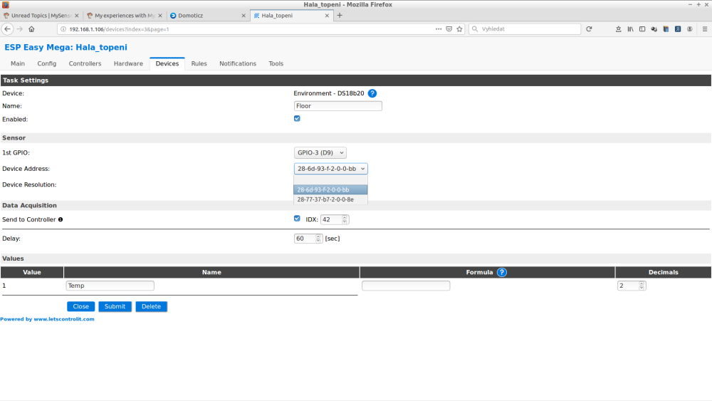
All without the need to compile a new program.
And you can send to your controller what you want, not just what is implemented in MySensors.
( Using JSON API in my case with Domoticz )
And your controller can send anything to your node.And for "MESH" topology.
Arduino "painlessMesh" library for ESPs exists.
But I think it is more easier to use more AP units - they are cheap .... -
RE: Graphing of time measured events - Solved
Domoticz has a nice dummy counter or dummy incremental counter, where you can enter the unit quantity.
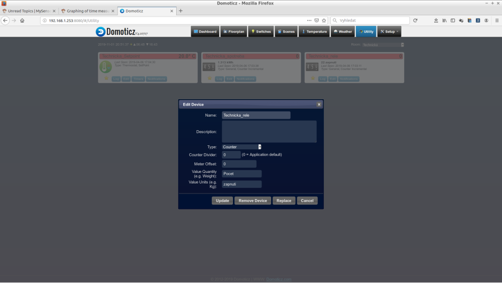
MySensors unfortunately is unable to send data to these counters.
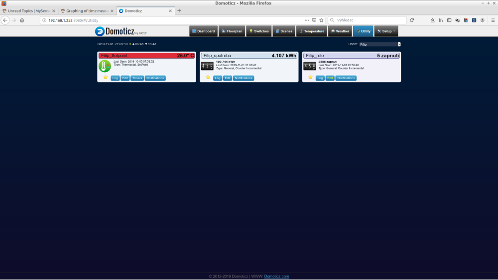
I am using them with ESP8266 to send energy consumption of my floor heating or number of actions of my relays.
So I recommend to use DzVents scripts in Domoticz instead of node-red.
I see two ways.
1.
Send from node for example in watts or m3 or litters.
With DzVents translate this value to time in minutes in Domoticz created dummy counter.Write DzVents script for your switch, which saves time for ON action and when OFF action occurs, calculate time interval and adds minutes to dummy counter.
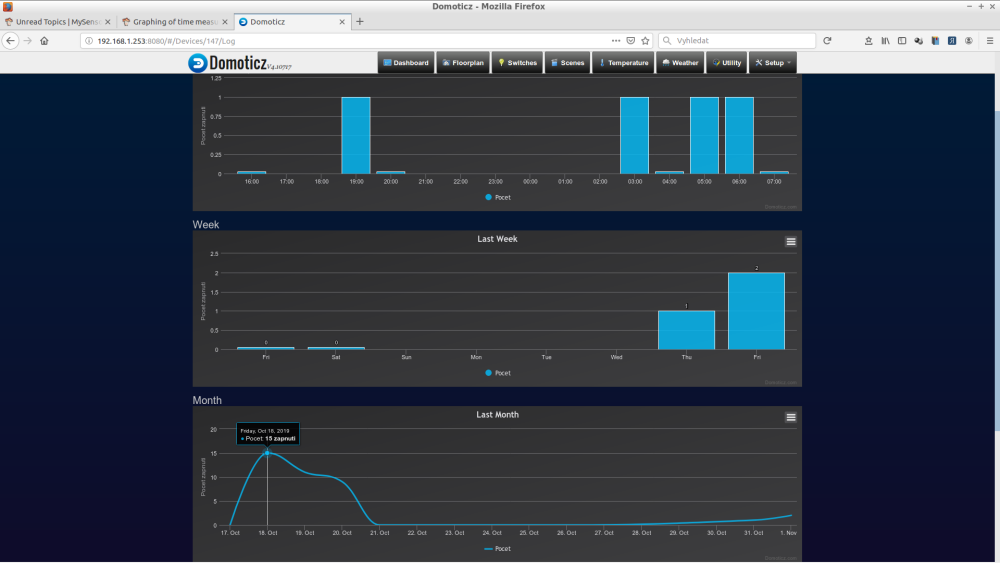
Then you can see the beautiful statistics for each day of the entire year back and the actual total value too.
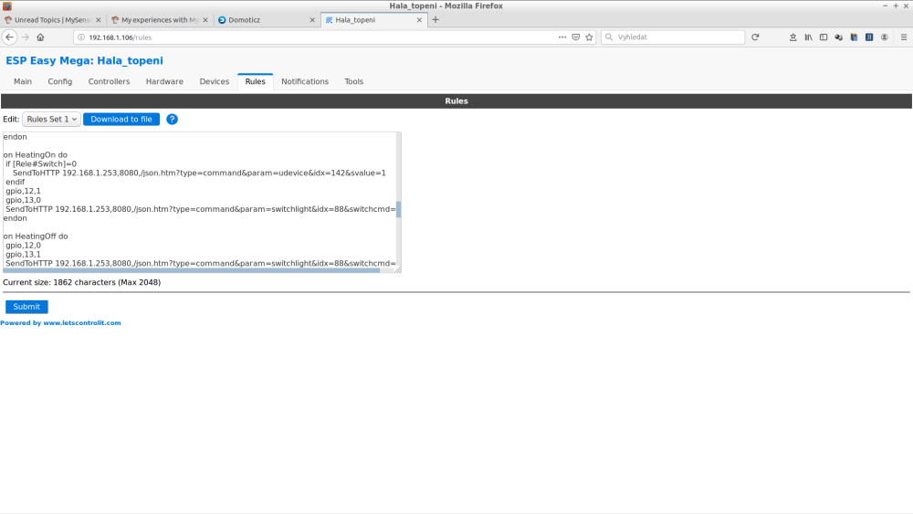
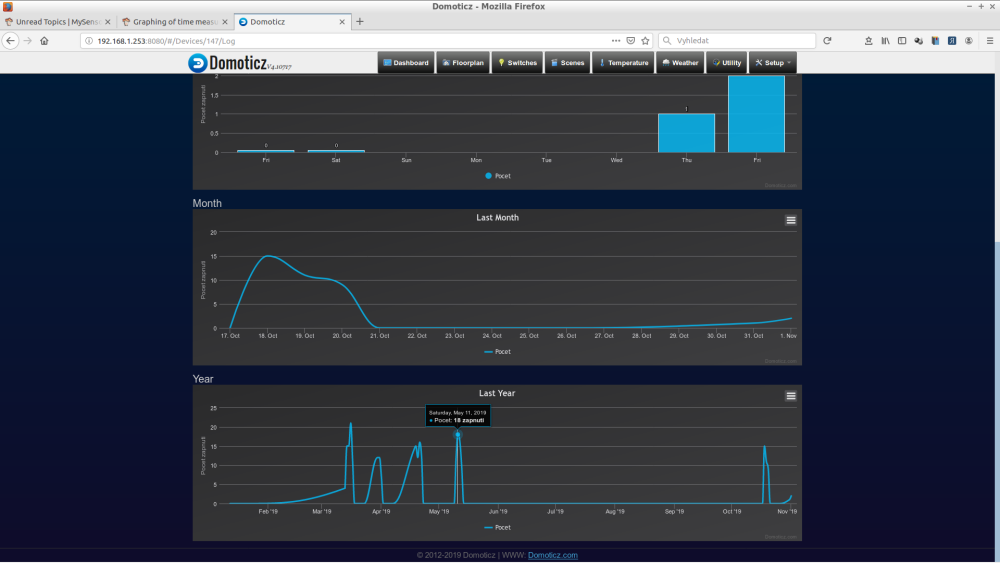
For example here for my relay actions:
( "zapnuti" = "relay on" ) -
RE: HM-TRP Gateway
It is 6 bytes sliding window which is filled from end and compared for correct byte order.
Here is _header loaded with data:_header[5] = inch
Maybe this helps:
-
RE: Door sensor with wifi
@jurimetrics
Yes, good battery life time, but not good response time.
You open the door and receive message about it after couple of seconds.
With Arduino and rfm69 or NRF24 it is much better. -
RE: HM-TRP Gateway
@chanky said in HM-TRP Gateway:
HM-TRP transceiver
Look at "MyTransportRS485.cpp and try adapt for your module which has serial communication too.
Initialize your module in "bool transportInit(void)" ?And etc.
A lot of work .....
-
RE: Door sensor with wifi
With battery powered sleeping wifi device will be always delay after door switch sensor action and message sending.
Find AP, connect to it etc.
Couple od seconds.
Maybe good for alarm, but not for switch light. -
RE: SerialGateway problem with install
So I think you do not need mysgw on RPi. I do not use openHAB, but Domoticz, but it must be similar.
Load serial gateway sketch to Arduino with radio module, connect this Arduino to USB port of your RPi and select serial gateway in openHAB. -
RE: SerialGateway problem with install
I do not understood your setup.
I see ttyUSB0, but your gateway runs on RPi - so nothing connected in USB.
I suppose radio module connected directly to your RPi. Or if your radio is connected to Arduino, load serial gateway sketch to that Arduino, not in RPi. -
RE: Node not working after adding some wires and a capacitor
Your NRF is 2.4GHz. Your Wemos and home WiFi network is 2.4GHz too.
Maybe your WiFi router randomly switch wifi channels to the chanel of your NRF network.
Try set fixed channel on your router. -
RE: ENC28J60 Ethernet gateway
ENC28J60 for a stable gateway is not a good idea.
Buy some Wiznet... -
RE: ๐ฌ RS485 Ethernet Gateway
I see in your code that you use:
#define MY_NODE_ID AUTO
Many users here have got a problem with the automatic allocation node ID with MySensors RS485 transmission protocol.
They must use manual ID allocation.
It really works for you?
Maybe the new versions of MySensors has this feature working.
It will be good news for me and others. -
RE: How can I monitor the humidity of a wall (house)
@pierrot10
And what about using normal soil moisture sensor and replace its pcb electrodes with something tougher.
Stainless steel nail knocked into wall or drill hole and put carbon rod from disassembled AA battery into it.
And experiment with electrode distance. -
RE: Mysensor usb gateway serial problem
@dany17
If you want to use arduino connected via usb to computer and your sensors connected to that arduino with MySensors, I recommend starting with sketch "GatewaySerialRS485" from MySensors examples and present your sensors in this sketch.
But honestly, I don't think you have enough experience for this task yet.
For example:byte value = analogRead(0); if (value == LOW){ delay(10); digitalWrite(gate, LOW); digitalWrite(relay1, LOW); delay(2000); digitalWrite(gate, HIGH); } if (value == HIGH){ delay(10); digitalWrite(gate, LOW); digitalWrite(relay1, HIGH); delay(2000); digitalWrite(gate, HIGH);
You compare analog readed value if it matches the exact value?
In how many cases does this occur?
And you know the value of the definition values LOW and HIGH in Arduino? -
RE: ESP8266 Gateway with AP mode instead of hardcoded ssid etc
But if you move ( or sold ) your gateway to different network, what seems as reason for selecting SSID and password,
you still need recompile your code due to different IP of your controller. -
RE: best solution to monitor and log power usage
Some Sonoff switching devices has got power metering.
Upload ESPeasy or Tasmota firmware and connect with HA.... -
RE: Encryption with RFM69 [solved]
#define MY_RFM69_ENABLE_ENCRYPTION
All nodes and gateway must have this enabled, and all must be personalized with the same AES key.
You need a helper-sketch specifically for this purpose- SecurityPersonalizer.ino
-
RE: Getting started with Wemos d1 mini & RFM69HW
Why you are using Wemos like normal node with RFM radio?
I assume you are building ethernet gateway with Wemos and RFM69.
Simply use my sketch fot gateway and your uno like node and try. -
RE: Getting started with Wemos d1 mini & RFM69HW
For your setup:
( change frequency and HW version)#define MY_RADIO_RFM69 #define MY_RFM69_FREQUENCY RFM69_433MHZ // Set your frequency here #define MY_IS_RFM69HW // Omit if your RFM is not "H" #define MY_RFM69_IRQ_PIN D1 #define MY_RFM69_IRQ_NUM MY_RFM69_IRQ_PIN #define MY_RFM69_CS_PIN D8 // NSS. Use MY_RFM69_SPI_CS for older versions (before 2.2.0)
With this setup and GW sketch from MySensors examples I am running this GW almost year without problem.
On Wemos D1// Enable debug prints to serial monitor #define MY_DEBUG // Use a bit lower baudrate for serial prints on ESP8266 than default in MyConfig.h #define MY_BAUD_RATE 9600 // Enables and select radio type (if attached) //#define MY_RADIO_NRF24 #define MY_RADIO_RFM69 #define MY_IS_RFM69HW // Omit if your RFM is not "H" #define MY_RF69_IRQ_PIN D1 #define MY_RF69_IRQ_NUM MY_RF69_IRQ_PIN #define MY_RFM69_CS_PIN D8 // NSS. Use MY_RF69_SPI_CS for older versions (before 2.2.0) //#define MY_RADIO_RFM95 #define MY_GATEWAY_ESP8266 #define MY_ESP8266_SSID "SSID" #define MY_ESP8266_PASSWORD "password" // Enable UDP communication //#define MY_USE_UDP // If using UDP you need to set MY_CONTROLLER_IP_ADDRESS below // Set the hostname for the WiFi Client. This is the hostname // it will pass to the DHCP server if not static. //#define MY_ESP8266_HOSTNAME "sensor-gateway" // Enable MY_IP_ADDRESS here if you want a static ip address (no DHCP) #define MY_IP_ADDRESS 192,168,1,252 // If using static ip you can define Gateway and Subnet address as well #define MY_IP_GATEWAY_ADDRESS 192,168,1,254 #define MY_IP_SUBNET_ADDRESS 255,255,255,0 // The port to keep open on node server mode #define MY_PORT 5003 // How many clients should be able to connect to this gateway (default 1) #define MY_GATEWAY_MAX_CLIENTS 2 // Controller ip address. Enables client mode (default is "server" mode). // Also enable this if MY_USE_UDP is used and you want sensor data sent somewhere. //#define MY_CONTROLLER_IP_ADDRESS 192, 168, 1, 17 // Enable inclusion mode //#define MY_INCLUSION_MODE_FEATURE // Enable Inclusion mode button on gateway //#define MY_INCLUSION_BUTTON_FEATURE // Set inclusion mode duration (in seconds) //#define MY_INCLUSION_MODE_DURATION 60 // Digital pin used for inclusion mode button //#define MY_INCLUSION_MODE_BUTTON_PIN 3 // Set blinking period //#define MY_DEFAULT_LED_BLINK_PERIOD 300 // Flash leds on rx/tx/err // Led pins used if blinking feature is enabled above //#define MY_DEFAULT_ERR_LED_PIN 16 // Error led pin //#define MY_DEFAULT_RX_LED_PIN 16 // Receive led pin //#define MY_DEFAULT_TX_LED_PIN 16 // the PCB, on board LED #if defined(MY_USE_UDP) #include <WiFiUdp.h> #endif #include <ESP8266WiFi.h> #include <MySensors.h> void setup() { // Setup locally attached sensors } void presentation() { // Present locally attached sensors here } void loop() { // Send locally attached sensors data here }```
-
RE: Water meter : grey scale sensor
And why you do not remove a half of plastic cover above rotating sensor wheel to put sensor closer?
-
RE: Reset values measured by Power Meter Pulse?
@koewacko
You can set negative offset 86kWh in Domoticz counter setup. -
RE: What did you build today (Pictures) ?
@zboblamont said in What did you build today (Pictures) ?:
umbillicals
It is rubber hoses with metal braiding.
But rubber degrades and this equipment is the most common cause of water leakage. -
RE: What did you build today (Pictures) ?
I think very useful device.
Stainless screw like detectors - no corrosion.
And all the time this device sits in dry area - no corrosion.
But software must call controller ( with battery level for example ) sometimes, say one per a day, to inform it is alive.
And if controller does not receive this message - sends alert.
I am using this for all my nodes - very easy in Domoticz.
If node dies, Domoticz send me e-mail ( and SMS ) with information.And 40 years with this hoses for example ?
Try it .....
-
RE: ๐ฌ Battery Powered Sensors
@tiana
Forever sleeping door sensor with low battery?"when last massage is send the node will never power the radio module"
Why door sensor, if it never sends message?
-
RE: ๐ฌ Battery Powered Sensors
@tiana
And for what will be that offline node usefull? -
RE: ๐ฌ Battery Powered Sensors
@tiana
Create dummy contact sensor on your node and if node sends last message, it will trigger this contact before "die".
So controller knows, that it was last message and node is off.
But better is allow controller do its job, like wrote all others.
I personally check battery level and "no incoming messages in supposed interval" to send alert to my e-mail ( and SMS ).
In this example tank level sensors sends every 10min, so after 3 messages lost, I will be informed. -
RE: Pls Help: Sensor value shows in Domoticz Hardware TAB, but wont show on Switches
@eme
I am not sure if Domoticz can know, what you want.
I am not MySensors expert, but there are some weird things in your code:#define CHILD_ID 0 MyMessage msgNEPA(0, V_STATUS); MyMessage msg(CHILD_ID, V_STATUS);
msg and msgNEPA are identical, but you use it in different ways ....
MyMessage msgTank1(1, V_VOLUME);
For CHILD ID 1 type of message V_VOLUME, but in loop:
for (int sensor=1, pin=RELAY_PIN; sensor<=NUMBER_OF_RELAYS; sensor++, pin++) { // Register all sensors to gw (they will be created as child devices) present(sensor, S_BINARY); pinMode(pin, OUTPUT); // Then set relay pins in output mode savedState = loadState(pin); // Set relay to last known state (using eeprom storage) digitalWrite(pin, savedState?RELAY_ON:RELAY_OFF); DEBUG_PRINT(F("Presented Relay st : ")); DEBUG_PRINTLN(F(pin)); send(msg.set(savedState? 0 : 1)); }
You present CHILID ID 1 like S_BINARY
And then you set to this binary sensor volume value:
send(msgTank1.set(tank_level("liters")));
And in the same presentation loop you send value only to child id 0, because msg.set send to ID 0
-
RE: No working window appaers after start.
mosquitto -v #start in verbose mode
If your mosquito is already running, you cannot start it again.
First stop it:
sudo service mosquitto stop sudo systemctl stop mosquitto.service
And then try your:
mosquitto -v
-
RE: No working window appaers after start.
@mslv129jdg said in No working window appaers after start.:
Error: Address already in use
I do not use Mosquito, but maybe it is already running automatically after RPI starts?
-
RE: ds18b20 on 2xAAA battery
@pihome
said in ds18b20 on 2xAAA battery:i wanted to ask what others are doing and how they are managing voltage for voltage hungry sensors
One useful "switch" you have got on your PRO MINI.
My from ebay has got LDO marked LG33, which is MIC5219 LDO with shutdown pin capability.
So remove one from arduino hacked for ultra low consumption and use it for switch power hungry sensors.Or only unsolder and bend up from pcb output and shutdown pin of LDO.
Then you can use 3AAA to power directly VCC ( 4.5V ). Connect this to RAW pin ( input LDO ) too.
Your sensors connect to unsoldered LDO output pin and shutdown pin connect with some output IO to drive your sensors ON/OFF.
Problem can be, that sensors run on 3.3V and your Arduino runs on 4.5V.
So you can put some diodes in series between battery and Vcc pin. Each diode ( not LED ) drops about 0.6V ( try different diodes ).
Another interesting idea with this LDO can be seen here: -
RE: Problems with the neighbours
@stevanov
It seems, that both of you use MySensors in "outofbox" state.
You do not write which radio module are using.
If RFM69 - change netwotk ID, with NRF24 change channel or network ID
Somewhere in config files.MyConfig.h
#define MY_RF24_CHANNEL (76) /** * @def MY_RF24_BASE_RADIO_ID * @brief RF24 radio network identifier. * * This acts as base value for sensor nodeId addresses. Change this (or channel) if you have more * than one sensor network. */ #ifndef MY_RF24_BASE_RADIO_ID #define MY_RF24_BASE_RADIO_ID 0x00,0xFC,0xE1,0xA8,0xA8 #endif /** * @def MY_RFM69_NETWORKID * @brief RFM69 Network ID. Use the same for all nodes that will talk to each other. */ #ifndef MY_RFM69_NETWORKID #define MY_RFM69_NETWORKID (100) #endif
Of course you must reprogram all nodes and gateway :o(
Or talk with your neighbours and ask them using different network ID if they only starting building their network and have got smaller number of sensors.
-
RE: ds18b20 on 2xAAA battery
@pihome
very power hungry (Quiescent current 13uA) ?
And do you know, that with AAA (1000 mAh) it is 8 years in standby?
Maybe self discharge is greater.
Alternetively use 3xAAA with low quiescent current 3.3V LDO. -
RE: Want Wired Ethernet For All Sensor Nodes / Gateway
Sorry, but if you have got ethernet on each node, why using MS gateway? Simple use pure MQTT and publish to the broker. You only need MQTT library, not all MySensors in this case.
-
RE: Battery Tank level node and Openhab
I do not know openhab, but in Domoticz this info ( battery and radio level ) I can see only in all devices list tab. Not like special sensor.
-
RE: Lux sensor (BH1750) sending battery level (V)
@bgunnarb
But readVcc returns longlong readVcc() { long result; // Read 1.1V reference against AVcc ADMUX = _BV(REFS0) | _BV(MUX3) | _BV(MUX2) | _BV(MUX1); delay(2); // Wait for Vref to settle ADCSRA |= _BV(ADSC); // Convert while (bit_is_set(ADCSRA,ADSC)); result = ADCL; result |= ADCH<<8; result = 1126400L / result; // Back-calculate AVcc in mV return result; }```
-
RE: Monitoring 2 x 18650 batteries
My way for monitoring battery.
Usually I have not got precise resistor with tolerance +-0.5% etc. for correct calculation, so I build resistor divider with what I approximately found.
Load my device with simple sketch, which reads data from ADC and write this raw ADC data to serial port.
I make notice, that for example 1009 corresponds to 6041mV with fresh battery measured with multimeter.
In my final sketch then using "magic" map Arduino function:int raw_volt = analogRead(A1); int volt = map(raw_volt, 0, 1009, 0, 6041);
Not very useful for "mass production", but for my prototyping it is ok.
-
RE: Nano minimum voltage
@bjacobse said in Nano minimum voltage:
Datasheet: The device operates between 1.8-5.5 volts.
and this means to bypass/remove the voltage regulator on the Nano boardBut it do NOT means with 16Mhz crystal on Arduino Nano ...
-
RE: Nano minimum voltage
Why "plus" 7805.
Nano has got voltage regulator on board.
Original Arduinos 7805 I think, clones LM1117 usually. -
RE: Never been able to get MySensors to work
Sorry, but you select most difficult way for build your sensor network.
You spare one arduino like serial gateway or one Wemos like ethernet wifi gateway and two years hacking RPI gateway with no result.
And you choose bad radio module too, I think. Instead of NRF24 use RFM69 and no more problems with distance in your home and mesh network function no needed.
For all beginners I recommended step by step solution of problems, if something do not works.
For example, first try simple communication between two modules using basic examples from RFM69 library for example.
If it works, you have got certainty, that your hardware is OK ( radio properly connected to arduino ).
Then you can load sketches for gateway and normal node to both modules and I bet, it will work. -
RE: 2 Arduinos using the one radio. Possible?
I think it is not very difficult sharing radio between two Arduinos.
But only for sending ...
Simply hold CS signal off for both Arduinos.
And connect both of them by signal, which tell each other if it is sending.
Other Arduino must wait for indication, that radio is free.
And radio initialisation only from one of them too. -
RE: Atmega328P + RFM69HW(868) not working
Try my 100% working testing setup:
Wemos D1 gateway:
/** * The MySensors Arduino library handles the wireless radio link and protocol * between your home built sensors/actuators and HA controller of choice. * The sensors forms a self healing radio network with optional repeaters. Each * repeater and gateway builds a routing tables in EEPROM which keeps track of the * network topology allowing messages to be routed to nodes. * * Created by Henrik Ekblad <henrik.ekblad@mysensors.org> * Copyright (C) 2013-2015 Sensnology AB * Full contributor list: https://github.com/mysensors/Arduino/graphs/contributors * * Documentation: http://www.mysensors.org * Support Forum: http://forum.mysensors.org * * This program is free software; you can redistribute it and/or * modify it under the terms of the GNU General Public License * version 2 as published by the Free Software Foundation. * ******************************* * * REVISION HISTORY * Version 1.0 - Henrik EKblad * Contribution by a-lurker and Anticimex, * Contribution by Norbert Truchsess <norbert.truchsess@t-online.de> * Contribution by Ivo Pullens (ESP8266 support) * * DESCRIPTION * The EthernetGateway sends data received from sensors to the WiFi link. * The gateway also accepts input on ethernet interface, which is then sent out to the radio network. * * VERA CONFIGURATION: * Enter "ip-number:port" in the ip-field of the Arduino GW device. This will temporarily override any serial configuration for the Vera plugin. * E.g. If you want to use the defualt values in this sketch enter: 192.168.178.66:5003 * * LED purposes: * - To use the feature, uncomment any of the MY_DEFAULT_xx_LED_PINs in your sketch, only the LEDs that is defined is used. * - RX (green) - blink fast on radio message recieved. In inclusion mode will blink fast only on presentation recieved * - TX (yellow) - blink fast on radio message transmitted. In inclusion mode will blink slowly * - ERR (red) - fast blink on error during transmission error or recieve crc error * * See http://www.mysensors.org/build/esp8266_gateway for wiring instructions. * nRF24L01+ ESP8266 * VCC VCC * CE GPIO4 * CSN/CS GPIO15 * SCK GPIO14 * MISO GPIO12 * MOSI GPIO13 * GND GND * * Not all ESP8266 modules have all pins available on their external interface. * This code has been tested on an ESP-12 module. * The ESP8266 requires a certain pin configuration to download code, and another one to run code: * - Connect REST (reset) via 10K pullup resistor to VCC, and via switch to GND ('reset switch') * - Connect GPIO15 via 10K pulldown resistor to GND * - Connect CH_PD via 10K resistor to VCC * - Connect GPIO2 via 10K resistor to VCC * - Connect GPIO0 via 10K resistor to VCC, and via switch to GND ('bootload switch') * * Inclusion mode button: * - Connect GPIO5 via switch to GND ('inclusion switch') * * Hardware SHA204 signing is currently not supported! * * Make sure to fill in your ssid and WiFi password below for ssid & pass. */ // Enable debug prints to serial monitor #define MY_DEBUG // Use a bit lower baudrate for serial prints on ESP8266 than default in MyConfig.h #define MY_BAUD_RATE 9600 // Enables and select radio type (if attached) //#define MY_RADIO_NRF24 #define MY_RADIO_RFM69 #define MY_IS_RFM69HW // Omit if your RFM is not "H" #define MY_RF69_IRQ_PIN D1 #define MY_RF69_IRQ_NUM MY_RF69_IRQ_PIN #define MY_RFM69_CS_PIN D8 // NSS. Use MY_RF69_SPI_CS for older versions (before 2.2.0) //#define MY_RADIO_RFM95 #define MY_GATEWAY_ESP8266 #define MY_ESP8266_SSID "SSID" #define MY_ESP8266_PASSWORD "password" // Enable UDP communication //#define MY_USE_UDP // If using UDP you need to set MY_CONTROLLER_IP_ADDRESS below // Set the hostname for the WiFi Client. This is the hostname // it will pass to the DHCP server if not static. //#define MY_ESP8266_HOSTNAME "sensor-gateway" // Enable MY_IP_ADDRESS here if you want a static ip address (no DHCP) #define MY_IP_ADDRESS 192,168,1,252 // If using static ip you can define Gateway and Subnet address as well #define MY_IP_GATEWAY_ADDRESS 192,168,1,254 #define MY_IP_SUBNET_ADDRESS 255,255,255,0 // The port to keep open on node server mode #define MY_PORT 5003 // How many clients should be able to connect to this gateway (default 1) #define MY_GATEWAY_MAX_CLIENTS 2 // Controller ip address. Enables client mode (default is "server" mode). // Also enable this if MY_USE_UDP is used and you want sensor data sent somewhere. //#define MY_CONTROLLER_IP_ADDRESS 192, 168, 1, 17 // Enable inclusion mode //#define MY_INCLUSION_MODE_FEATURE // Enable Inclusion mode button on gateway //#define MY_INCLUSION_BUTTON_FEATURE // Set inclusion mode duration (in seconds) //#define MY_INCLUSION_MODE_DURATION 60 // Digital pin used for inclusion mode button //#define MY_INCLUSION_MODE_BUTTON_PIN 3 // Set blinking period //#define MY_DEFAULT_LED_BLINK_PERIOD 300 // Flash leds on rx/tx/err // Led pins used if blinking feature is enabled above //#define MY_DEFAULT_ERR_LED_PIN 16 // Error led pin //#define MY_DEFAULT_RX_LED_PIN 16 // Receive led pin //#define MY_DEFAULT_TX_LED_PIN 16 // the PCB, on board LED #if defined(MY_USE_UDP) #include <WiFiUdp.h> #endif #include <ESP8266WiFi.h> #include <MySensors.h> void setup() { // Setup locally attached sensors } void presentation() { // Present locally attached sensors here } void loop() { // Send locally attached sensors data here }
Node - motion sensor:
/** * The MySensors Arduino library handles the wireless radio link and protocol * between your home built sensors/actuators and HA controller of choice. * The sensors forms a self healing radio network with optional repeaters. Each * repeater and gateway builds a routing tables in EEPROM which keeps track of the * network topology allowing messages to be routed to nodes. * * Created by Henrik Ekblad <henrik.ekblad@mysensors.org> * Copyright (C) 2013-2015 Sensnology AB * Full contributor list: https://github.com/mysensors/Arduino/graphs/contributors * * Documentation: http://www.mysensors.org * Support Forum: http://forum.mysensors.org * * This program is free software; you can redistribute it and/or * modify it under the terms of the GNU General Public License * version 2 as published by the Free Software Foundation. * ******************************* * * REVISION HISTORY * Version 1.0 - Henrik Ekblad * * DESCRIPTION * Motion Sensor example using HC-SR501 * http://www.mysensors.org/build/motion * */ // Enable debug prints #define MY_DEBUG // RFM69 #define MY_RADIO_RFM69 #define MY_IS_RFM69HW //#define MY_RFM69_NEW_DRIVER // ATC on RFM69 works only with the new driver (not compatible with old=default driver) //#define MY_RFM69_ATC_TARGET_RSSI_DBM (-70) // target RSSI -70dBm //#define MY_RFM69_MAX_POWER_LEVEL_DBM (10) // max. TX power 10dBm = 10mW // RFM95 //#define MY_RADIO_RFM95 //#define MY_RFM95_ATC_TARGET_RSSI_DBM (-70) // target RSSI -70dBm //#define MY_RFM95_MAX_POWER_LEVEL_DBM (10) // max. TX power 10dBm = 10mW #define MY_NODE_ID 20 #include <MySensors.h> uint32_t SLEEP_TIME = 120000; // Sleep time between reports (in milliseconds) #define DIGITAL_INPUT_SENSOR 3 // The digital input you attached your motion sensor. (Only 2 and 3 generates interrupt!) #define CHILD_ID 1 // Id of the sensor child // Initialize motion message MyMessage msg(CHILD_ID, V_TRIPPED); void setup() { pinMode(DIGITAL_INPUT_SENSOR, INPUT_PULLUP); // sets the motion sensor digital pin as input } void presentation() { // Send the sketch version information to the gateway and Controller sendSketchInfo("Motion Sensor 2", "1.0"); // Register all sensors to gw (they will be created as child devices) present(CHILD_ID, S_MOTION); } void loop() { // Read digital motion value bool tripped = digitalRead(DIGITAL_INPUT_SENSOR) == HIGH; Serial.println(tripped); send(msg.set(tripped?"1":"0")); // Send tripped value to gw // Sleep until interrupt comes in on motion sensor. Send update every two minute. sleep(digitalPinToInterrupt(DIGITAL_INPUT_SENSOR), CHANGE, SLEEP_TIME); }
Antena - piece of wire on both sides.
Receiving distance - min 60m ( gateway at home, sensor in garden )
-
RE: Can we increase the number of nodes from 254 to 1024 or more?
Do not forgot, that some radios ( RFM69 ) allow only 255 address in one network.
No way connect more nodes to all receiving all messages ... -
RE: Solar powered node, that should only send occasionally
I am using HC-SR04 for reading water level too.
My measuring range is 110 cm = empty tank, 2 cm = full tank. ( this is now ).Only problem I have got - when it is raining, some water drops condenses on sensor at night and sensor sends zero value.
Or I need better cover for my sensor ...
I eliminate by Domoticz code these bad readings.I send to Domoticz actual distance and battery voltage every 10 minutes and calculate volume in m3 and percentage and water influx or consumption.
I am using battery powered Arduino Mini with MySensors network.
Only power led removed - consumption in sleep 70microA.
I am cutting off power for SR04 during sleep with small relay too and then it power on again.
There is a little delay before distance measuring and I read three times distance and use only last reading, because independently on delay time, first readings returns zero value sometimes after power on sr04...Another problem is, that I power SR04 directly from battery, which voltage changes a little according ambient temperature.
Using voltage stabilizer for SR04 will be necessarily.
It was very quick project ... -
RE: WakeOnLan over nrf24 radio
@tommas
And what about setting it in BIOS of your PC?
It is normal function for PC. -
RE: Ideal Sensor read interval
It depends on type of your radio module too. With 868Mhz modules you can transmit for example only 1 percent of time per hour. ( In our country )
So if you send every minute, your transmit time can be max 0.6 sec. -
RE: help with serial gateway on raspberry pi
@fernando-alvarez-buylla
I think you only need define your gateway in Domoticz.
That Is all.
-
RE: Failed to make encryption work on a barebone ATMEGA328P
@encrypt
I am not sure, if we speak about the same AES key.
I mean encryption key for RFM69 chip, because you select using encryption by this radio in your network.
But I am on my mobile only, so it is dificult study source codes Now. -
RE: Failed to make encryption work on a barebone ATMEGA328P
@encrypt
I do not see encryption kye for RFM69 in your code... -
RE: Pan Tilt stepper motors
When you switch off power for servos, they will stay in last position. And they have got a gear so not too easy self moving like single steppers.
And pan tilt kits are very cheap. -
RE: RF Nano = Nano + NRF24, for just $3,50 on Aliexpress
@alowhum
For me top user friendly is ESPeasy.
Through web interface selecting which sensors on which pins connected and to which controller send data.
When user become more experienced, he can use rules to write some "programs".
No recompilation needed.
But not useful for battery powered nodes which needs receive some data. -
RE: Pan Tilt stepper motors
And what kit with stepper motors? Or you mean servo motors ?
-
RE: Female-female header connectors?
You realy think, that it Is useful fรณr connecting two male connectors together, what way asked?
-
RE: DHT and DOOR sensor
@terence-faul
comment step by step blocks of code for DOOR switch and try when it start to work. -
RE: Using an 802.11g wifi transport
If you plan using ESP chips or Raspberry as your sensors node, I think better way is ESPeasy or similar sw for ESPs.
-
RE: ๐ฌ MyThermostat
How do you solve a situation where a SSR breakdown occurs and you are hunderts km away from home?
I think some classic relay is necessary in this application to handle error conditions.
Similarly, measuring the temperature in the blast near SSR is not very accurate. -
RE: How to protect rain sensor from oxidation?
Piezo detector exists for detecting the impact of the drop.
-
RE: ๐ฌ RS485 MCU Module
It is a very interesting board for RS485 applications (modbus etc.).
But not quite right for Mysensors serial bus. RS485 is not designed for multimaster bus.
CAN bus drivers are most preferable. -
RE: Combined electricity, gas and water use sensor
You are probably the exception that you have electricity, gas and water gauges side by side and you can read them with one device.
-
RE: WAF in jeopardy today
@dbemowsk
Yes, sometimes it got USB1 instead of USB0.
You can create fix symlink for your USBtoSerial adapter and then write for example ttySonoff and allways will be right. -
RE: Thanks to all
@fernando-alvarez-buylla
ESP with Tasmota or ESPeasy is good solution for sensors where power is available. But if you must use battery, you must find something different. And then MySensors with RFM69 radio (not your 2.4GHz NRF24L01 ) can be good choice. It has a lot of better distance on 848 or 433MHz. -
RE: Problem with sensors on arduino and domoticz
@hyperflemme
Use gateway sketch and add sensor presentation and sensor data sending like in node sketch.example from this forum:
void presentation() { // Present locally attached sensors here // Send the sketch version information to the gateway and Controller sendSketchInfo("AWI_ESP 120", "1.0"); // Register all sensors to gw (they will be created as child devices) present(CHILD_ID, S_DIMMER, "AWI_ESP 120" " dimmer"); present(CHILD_ID2, S_INFO, "AWI_ESP 120" " text"); } void loop() { // Send locally attached sensors data here send(msg.set(messageCounter)); // Send message to gw messageCounter = ++messageCounter % 100 ; // wrap send(msg2.set("Hallo")); // Send message to gw // Send update every SLEEP_TIME wait(SLEEP_TIME) ; } void receive(const MyMessage &message) { // messages from node or controller //char printBuf[40] ; //Serial.print(message.getInt()); //sprintf(printBuf, "Message node: %d %d OK\n", message.sender, message.getInt()); } //Serial.print(printBuf) ; //sprintf(printBuf, "Messages: %d Errors: %d\n", messageCounter, messageErrorCounter); //Serial.print(printBuf) ;
Search forum here, you are not alone with this solution.
-
RE: WAF in jeopardy today
You must install esptool:
https://diyprojects.io/esp-easy-flash-firmware-esptool-py-esp8266/
or
https://github.com/arendst/Sonoff-Tasmota/wiki/Esptool#esptool-executable-windows--linuxAttention, there are some dependencies...
Then normally go to folder where .bin file is placed and run command:
esptool.py --port /dev/ttyUSB0 --baud 115200 write_flash 0x00000 ESP_Easy_v2.0-20180322_normal_ESP8285_1024.bin
or
python esptool.py .........................
not ./esptool.py
But I suggest first try :
esptool.py --port /dev/ttyUSB0 flash_id
To check if every is OK ( port, etc )
-
RE: Problem with sensors on arduino and domoticz
I think we still do not know the topology of your network and we use different terms.
For most of us a "sensor" is - temperature sensor, humidity sensor, pressure sensor, etc. These sensors are connected to Arduino, which we call the "node".
These node are connected through radio or RS485 to Arduino which works like gateway and send received messages from nodes to controller ( Rpi with Domoticz ).
Usually gateway have got no sensors and you can use pure gateway sketch from examples.
But you can connect sensors directly to gateway, but you must modify gateway sketch then.- setup your sensors
- present your sensors
- send values form your sensors.
And of course NO SLEEP FUNCTION in sensor send code.
Places, where put it is marked by comments in gateway sketch:
void setup() { // Setup locally attached sensors } void presentation() { // Present locally attached sensors } void loop() { // Send locally attached sensor data here }
Usual topology:
I think your topology:
-
RE: WAF in jeopardy today
@dbemowsk
It is from here:
https://github.com/letscontrolit/ESPEasy/releases/tag/v2.0-20180322I connect it like you wrote.
-
RE: RS485 & SoftwareSerial
@paweld
And must you really use SoftwareSerial and not AltSoftSerial, which is default for MySensors RS485 link layer?
You do not need include SoftwareSerial in your sketch then. -
RE: WAF in jeopardy today
@dbemowsk
I have 12 of these new and working without any problems.
There is a missing gpio14 pin, where I connected the DS18B20, but I used the RX pin instead.
PCB design is more solid to me - you can even see the power fuse.
ESPeasy flashing without problem using esptool.
My way to program new Sonoffs:To check comunication:
esptool.py --port /dev/ttyUSB0 flash_idErase flash:
esptool.py --port /dev/ttyUSB0 erase_flashProgram ESPeasy bin:
esptool.py --port /dev/ttyUSB0 --baud 115200 write_flash 0x00000 ESP_Easy_v2.0-20180322_normal_ESP8285_1024.binLook here:
https://www.letscontrolit.com/forum/viewtopic.php?f=4&t=6415&p=35265#p35265 -
RE: RS485 & SoftwareSerial
A long time before I try serial gateway from MySensors example and it works without any modification.
My configuration:
Domoticz
Pro mini like serial gateway - hw serial to Domoticz, sw serial to another Pro mini with serial motion node example with serial sw from MySensors too.
But no RS485 drivers, only sw serial tx and rx pins cross wired.
And do not forgot assign node_id in your sketch. -
RE: WAF in jeopardy today
Can you connect to Sonoffs web pages?
Or can you see its SSID if they are in AP mode?
My Sonoffs Basic is switched off four times per every day and works like charm.
No DHCP, fixed IP, Domoticz. It is the most stable part of my sensors network.
It Is not probable, that all of yours are bad.
It must je different problem. -
RE: Problem with sensors on arduino and domoticz
@hyperflemme
Than in your second sketch ( with sensors )
define MY_GATEWAY_SERIAL
is missing.
This sketch works like normal node without this, not as gateway with sensors connected. -
RE: 433mhz chinese burglar alarm and openHAB
I am not using OpenHAB but Domoticz.
But I think, that RFLink or RFXCom will help you with OpenHAB top. -
RE: Determine if pin interupt or awakens from sleep
Create a global variable and set to 0.
In the interrupt handler subroutine, set it to 1.
Check its status in the main program to determine if an interruption has occurred.if (my_global_variable == 1) my_global_variable = 0; {do this} / Action if an interrupt has occurred if (awkens from sleep) {do that}```
-
RE: Need some help with this sensor setup for RF remote
RFLink to your controller plus 4 button RF senders from ebay.
-
RE: Problem with sensors on arduino and domoticz
Do you connect your sensor to the same mega2560 which works like serial gateway or are you using different mega2560 connected through radio to serial gateway mega2560?
-
RE: [SOLVED] Puzzle over water meter .sensor
@zboblamont
I'm sorry to let you know that you are using Atmega328p outside the manufacturer-guaranteed specifications.
My apology again
But your super "Whisper NODE AVR" with onboard booster is very nice, but this booster "boost" to 3,3V.
And 16Mhz is out of range for ATmega328p at 3.3V
It wants a lot of courage to sell such a product for boys from WisenLook at circuit diagram:
https://bitbucket.org/talk2/whisper-node-avr/src/bad0f4f997dc9bae952d9aafd13397e1015eb602/Documentation/Whisper_Node-AVR_0.3.pdf?at=master&fileviewer=file-view-defaultI believe that it works in most cases, but there can be situations - noise, EMI, when a problem occurs for this reason.
Something like PRO-MINI with 8MHz is safer for me and I do not have problems with random events. -
RE: [SOLVED] Puzzle over water meter .sensor
Arduino 3V at 16MHz is out of specification. You cannot be surprised by no standart behavior.
-
RE: 2 dallas temp + 4 relays
For low number of DS18B20 and if you have got enough free pins,
I suggest use separate Arduino pin for each DS18B20.
Then your code is absolute universal and you always know, which pin what measure.
Do not matter, which DS18B20 you use.
With your method, you must read each DS18B20 signature - hardcoded it, compile and flash.
When sensor needs replacement due to malfunction - whole process again. -
RE: Sensor required to detect PVC insulated COPPER wire
@hard-shovel
But mesh is on other direction too - parallel with movement and sure not still at the same position and pure parallel.
So digital signal can be generated longer time than you expected.