I have been getting about a year from a coin cell on nrf52832 and BME280 sending temperature and humidity every 3 minutes. Good enough for me : )
nagelc
@nagelc
Posts
-
None nnn Node in Home Assistant -
None nnn Node in Home AssistantYeah, you need the sketch name.
I found that
wait()was required pretty much after every send. I don't why exactly, I suspect the the send commands were overrunning the previous send command.I second this. Waiting after send can help some odd behavior.
I have also had nodes the performed well with debug turned on, then not work when it is off. The debug prints are slow in processor time and I think they act like a wait. If this happens, check where you have debug messages and try some waits there, especially if it is after a send.
-
cppcheck old-style c castHi. I'm running cppcheck 2.18.3 Just grabbed the latest.
The above were from MyCryptoGeneric.cpp.
Perhaps some new checks were added since 2.1 -
cppcheck old-style c castI'm working on updates to adapt the STM32 driver for the STM32WL series and using the tools from the Contribution Guide.
When committing, I get a lot of cppcheck errors in the existing code, mostly this one:warning: Potentially invalid type conversion in old-style C cast, clarify/fix with C++ cast [dangerousTypeCast]I'm sure I could figure this out, but hate to mess with working code. What's the MySensors philosophy here? If I don't fix it now, how do you get thru the cppcheck to commit?
Thanks in advance for any advice. I mostly just write code for myself, so am a bit of a noob at contributing back.
-
Advice on how to start my IOT projectI'm not sure about Tart, but Grove is an interface for I2C that is used by Seeed studio. With the right connector, it should be easy to make a Grove compatible MySensors node. Adafruit has Stemma and Sparkfun has Qwiic. These are all similar ways to make I2C sensors more plug and play (at least from a hardware perspective).
-
Wio-E5 (STM32 and SX1262)Thanks @Sasquatch. I did some testing also. The values below seem to be the correct ones. I had similar -100 RSSI at all power settings when using the opposite settings. When I use these, I got reasonable RSSI's that changed approximately linearly with the power setting. I got at least 500m range with an E5-LE in a quick test. That's a 5x improvement and there were many obstacles and buildings in the path. I look forward to trying it somewhere where I have more line of sight. I made an update to my code on github.
{STM32WLx::MODE_TX_LP, {HIGH, HIGH}}, // For the E5-LE {STM32WLx::MODE_TX_HP, {LOW, HIGH}}, // For the regular E5 -
Home Assistant Serial Gateway with Supply rail monitoringIf you haven't used it, the log parser is really helpful: https://www.mysensors.org/build/parser
Makes it easy to see you are sending 0.00 for V_VOLTAGE. -
Home Assistant Serial Gateway with Supply rail monitoringThat None 0 Battery is the battery percentage from sendBatteryLevel(), which you aren't using in your sketch. You should be seeing an entry for the voltage you are sending besides that one.
Your message output indicates you are sending 0.00 for the voltage. Check the output of float batteryV = sensorValue * (4 / 1023) * 2; with a printf. If it comes out as zero, double check the sensorValue. Also check 4/1023. It would be zero if processed as an int. try 4.0/1023.0 and see if that helps. Even as a float it is a very small number. sensorValue would need to be about 128 for it to register as a 1.
I've had some challenges with floats and ints in the past -- admittedly not an expert. I should actually learn how arduino handles them : )Update: Duh I see it. 20 0V. So ignore what I said about None 0 Battery. You are sending 0V however. See below.
PS. I like HA for all the other stuff it can do besides MySensors, but I sometimes do miss Domoticz. -
Home Assistant Serial Gateway with Supply rail monitoringUpdate. Duh. I see you are getting the voltage to HA (20 0V ). So maybe ignore my original post.
In your presentation function, you present CHILD_ID twice. I think you just want to present it as S_MULTIMETER. Delete the V_VOLTAGE from presentation. Your MyMessage msgVolt declaration tells it that it is a V_VOLTAGE.
Not sure if this is the fix, but it is probably not correct as is. -
A year has passed...STM32 Core support was added to the dev branch this year. That adds a bunch of processors that can be used with MySensors. It also looks like @tekka is working on a 2.4.0 release. I see some updates from him in the dev branch.
-
Wio-E5 (STM32 and SX1262)@Sasquatch I have not found a good schematic of what is happening inside the WIO E5 Module. My only references were here from the wiki here:
https://wiki.seeedstudio.com/LoRa-E5_STM32WLE5JC_Module/
https://wiki.seeedstudio.com/LoRa_E5_Dev_Board/
These only address the high power WIO-E5, not the LE. They a reference to the WL55jc dev board. I found a document for that with this table:
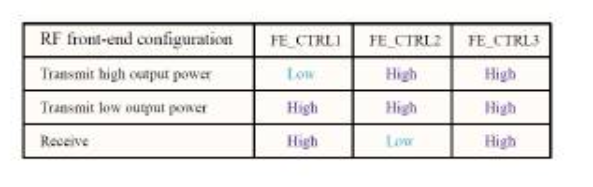
So, Maybe it should be HIGH, HIGH for the low power mode. I'm traveling now, but will do some experimenting when I get home. -
Setting parameters before system load@OldSurferDude Thanks!
-
Wio-E5 (STM32 and SX1262)Interesting. I hadn't thought about the antenna insulation. I usually grab the nearest hookup wire on my workbench. Will have to pay more attention to that. It easily reaches my basement and backyard, so I haven't been pushing for the most range.
I would love to find an OTA solution. Even if I had to solder on some external memory, it would be worth it.
-
Setting parameters before system load@OldSurferDude can you post your code to set MY_NODE_ID? I've been doing it in the sketch, and have recently messed up some of my existing data by forgetting to change the node number before uploading to the new node. Your method seems better than what I am doing now.
Looking forward to see what @mariusl comes up with. -
Pjon Script -
Pjon ScriptIt's in the development branch.
How do you plan to use it? Sounds fascinating, but I haven't quite been able to wrap my head around it. -
Sketch Names in Home Assistant - ResolvedI like the joke : )
I'll try to keep it simple. Most of my sensors are just reporting temperature and humidity. Since I can assign them to a room in home assistant. They don't need anything fancy.
-
Sketch Names in Home Assistant - ResolvedI moved my MySensors nodes from Domoticz to Home Assistant. Domoticz didn't really do anything with the sketch name. Home Assistant uses it in the device names.
I had named my sketches by processor and function, BT8_BME280 for example. This makes sense when programming, but makes the device names in Home Assistant seem rather random.
I can have the sketch present anything want for a sketch name. Maybe using just the node function would be better?
Anyone have a naming system that makes sense in Home Assistant?Update. There is a lot of thinking about this online. For example: https://github.com/Trikos/Home-Assistant-Naming-Convention
But also, I can rename in home assistant, so doing it in the sketch isn't that important. -
MySensors Gateway Controller Failed to ACK I_FIND_PARENT Request from NodeYour analysis of the problem seems correct.
This sounds very frustrating, and I am afraid I can't help much.From your earlier post, the transport is just shutting down because it had too many failed attempts to find a parent. That is normal operation. My memory is that it will just try again after a while.
-
Support for CC1101 radiosNice. I know there are RFM69's, but I've seen quite a few requests for the CC1101. Always good to have options.
I did something similar with the WIO-E5 chips in my repo. The E5 is not quite ready for prime time, but the basics are working.
I have many MySensors nodes, and still adding more. Good to see some new code for it.