Self Powered Inline AC Double Relay Module
-
Self Powered Inline AC Double Relay Module
I've come up with the designs for a double relay module for AC power that can monitor/sense the current of the module and its attached relays. The primary use for these would be as lighting controllers/relays, being all powered from the same AC input, this should allow to be installed on the lighting circuit that you wish to control and allow for one more circuit to be controlled/isolated. Being the size that it is (50mm square) we are able to fit this into the ceiling or wall, away from sight and allow for 2 manual switches to be wired directly onto the module itself or allowing the use for another type of switch, even that of the wireless light switch module i have previously created here.
Module Requirements
- Be small as possible.
- Be as safe as possible.
- Allow for use in sheltered outdoor applications.
- Sense and monitor its current usage.
- Have 2 external switch terminals, manual switching may be needed.
- Have Atsha204 signing for security in outdoor applications.
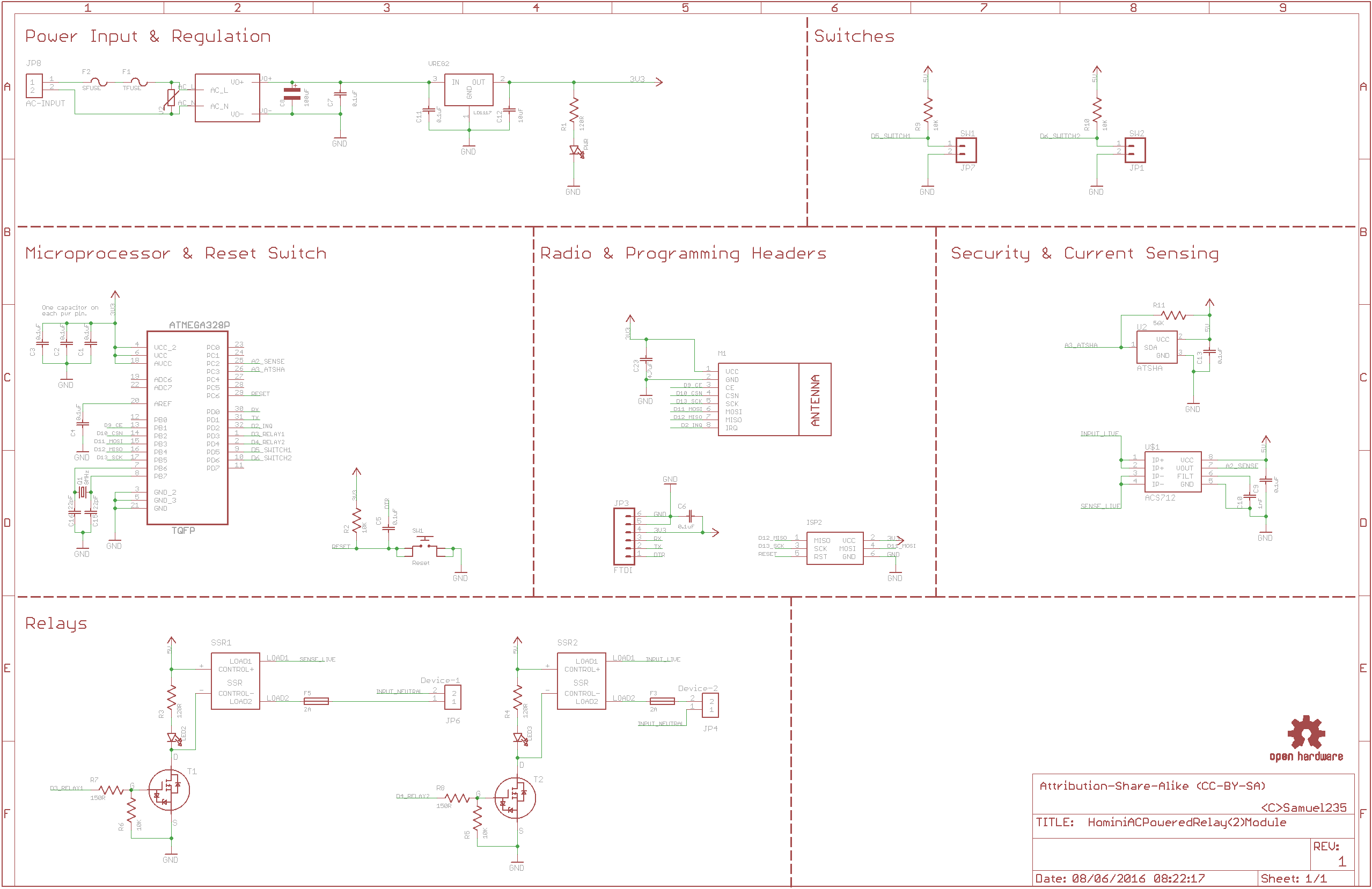
So after many nights of researching, designing and brainstorming I have completed the first drafts of designs for this module. The module includes; Slow blow fuse, AC transformer to generate 5V DC power on-board, 2 x 2A fuses for the relays to allow safety on-board rather than on the electricity main ring, Atsha204A signing, ACS712 current sensor and nRF24L01+ radio (Which is located in such a way that you can switch this out for the more powerful version if needed).
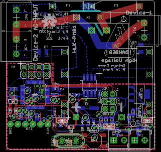
The module will fit on a 50mm x 50mm board to allow for cheaper production and smaller, more compact encasing. Most traces for the DC side of the board are all done in 6mm, I may increase the power lines slightly, if space allows. Vias are all done in a 0.3mm drill size, again i may attempt to increase these slightly if space allows. The below image of the board layout shows how untidy the routing is, it took me a while to get it all connected up and will be looking to tidy up my signal lines before production commences.
Upload Methods
The upload methods that i have included are FTDI and ISP. However, to gain advantage of either of these you will need to use POGO PINS or an alternative as there is no room for the physical header pins at the moment.
Images
Schematic:
Board View:
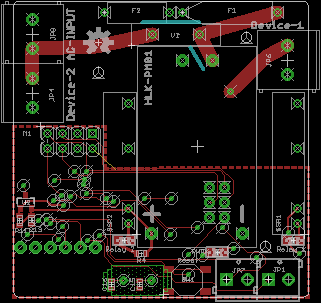
Board-Top View:
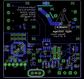
Board-Bottom View:
Files
HominiACPoweredRelay(2)Module.zip
All suggestions are more than welcome, they are encouraged actually.
-
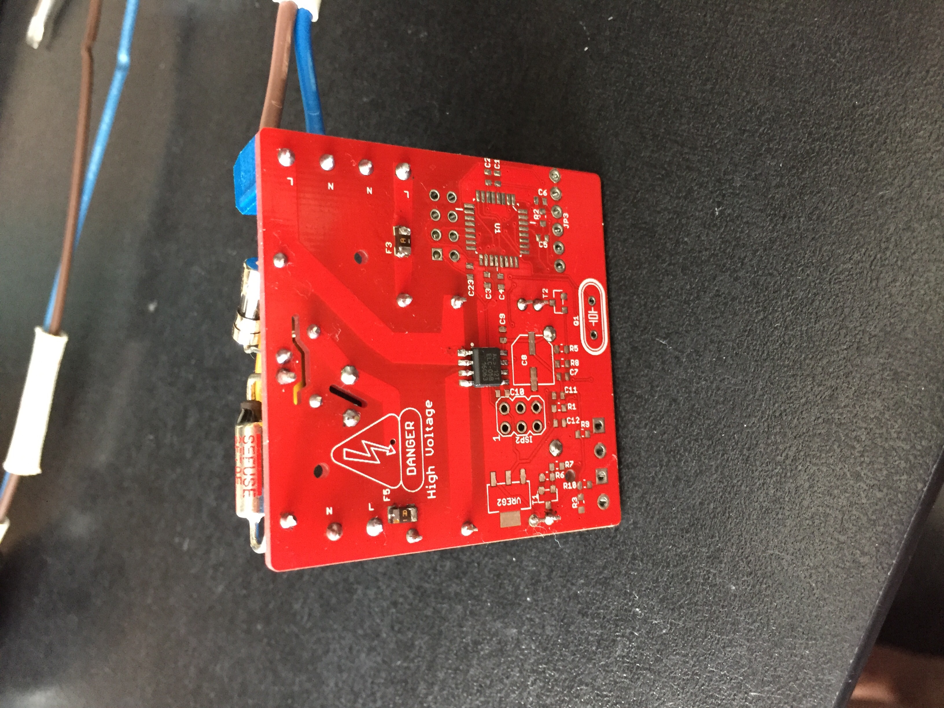
Updated the board with Logos and text for Mysensors.org, OpenHardware.io and High Voltage warnings. Updated images have now been updated in original post above.
-
The boards have arrived, with a very swiftly turn around with thanks to PCBWay.com. They have actually been here for a week now. I can not believe how quickly and the level of quality they have given this product, so a huge thank you to the guys/women over there!
I'm still currently waiting on a few parts to arrive to finish populating these boards and get them AC Power tested. I'm planning on running these for 24 hours with no DC load on there at all, just to monitor the AC circuitry before attempting to publish any documentation regarding these modules.
Keep checking for the updates ;)
-
I'm currently having an issue with one part, still waiting for the arrival of the ALLEGRO Current Sensors from aliexpress. Will post some images and test results as soon as they arrive.
-
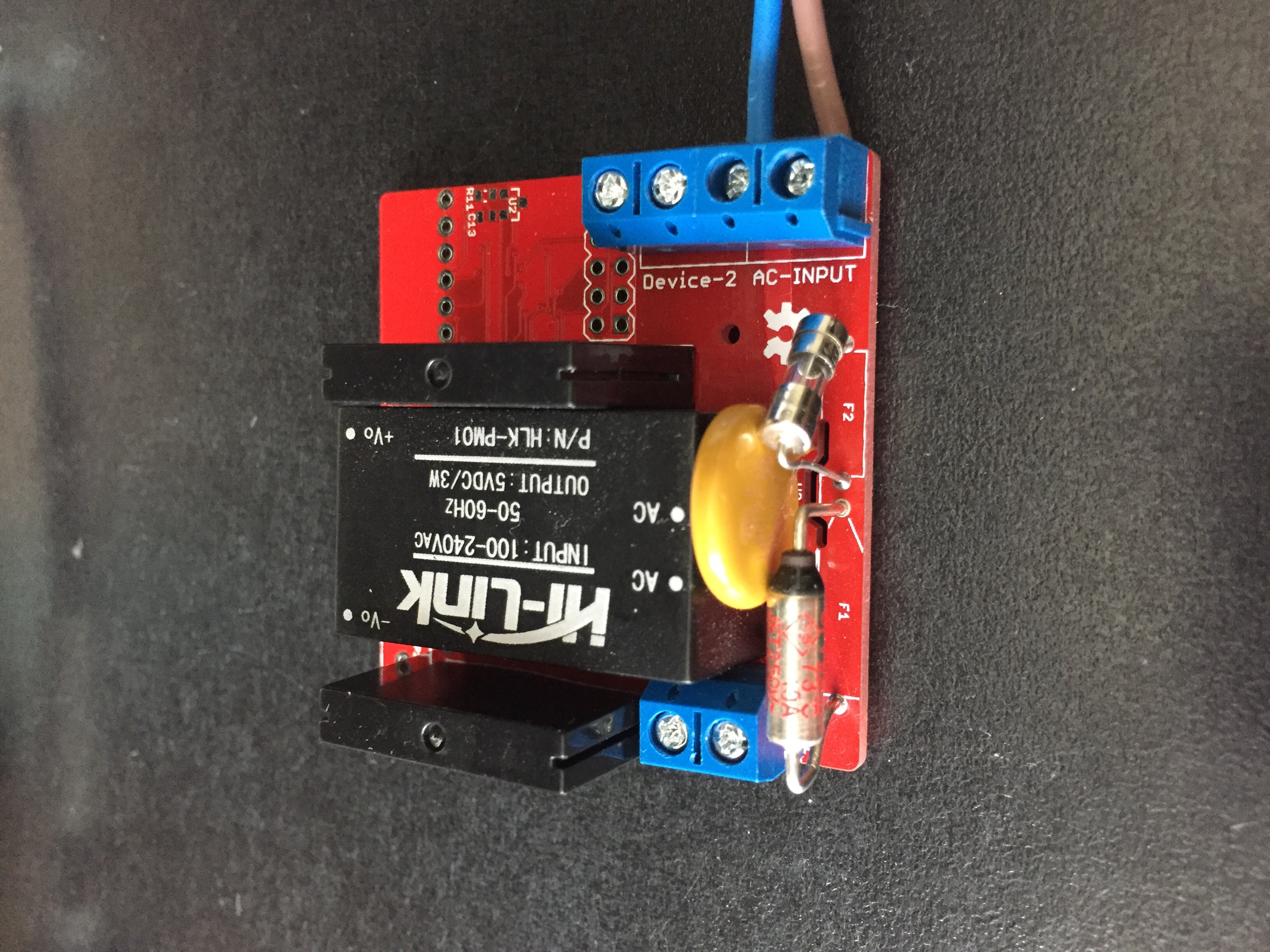
The current sensors have areived so i've thrown the high voltage section together on the board and about to 'idle' test the device.
First test will be a 1 hour period of no attached devices and no low voltage circuitry in place. Purely testing the high voltage side.
-
This looks realy nice, but isnt the thermal fuse supposed to be glued to the hi-link?
-
@Tore-André-Rosander said:
This looks realy nice, but isnt the thermal fuse supposed to be glued to the hi-link?
This would make the fuse blow to the tightest of sensitive changes IMO, i will trial without gluing to the HLK, and find some more information supporting this before i go ahead and commit to this suggestion.
It turns out, after getting the board completely populated, we have a short to ground on the vcc line on the Radio socket. Time to re-design the board and send off for for the new revision.
Revision 2 upgrades:
- Remove VCC short to GND on the radio socket
- Add some more detailed silkscreen that was left off by accident
- Make 1 device footprint bigger, allowing for easier soldering.
-
The updates have been applied to Rev 2, below we have a list of everything that has been added/modified;
- Modification footprint for 3 items to make it easier to mount (Slow blow fuse, Thermal Fuse and Voltage Regulator) when hand soldering.
- Modification to nRF24L01+ Module to remove the short to ground on VCC line.
- Added the additional silkscreen labeling that was missed off by accident.
This should be all that is needed for Rev 2 to be a successor to the Rev 1. We still have the issue with having to use pogo pins to program through the ISP connection, or to temporarily solder jumper wire into the 6 pin connection while uploading, then everything else can be programmed through the on-board FTDI connection.
Will get the gerber files generated ASAP and then get them sent off for testing production runs.
Hello! It looks like you're interested in this conversation, but you don't have an account yet.
Getting fed up of having to scroll through the same posts each visit? When you register for an account, you'll always come back to exactly where you were before, and choose to be notified of new replies (either via email, or push notification). You'll also be able to save bookmarks and upvote posts to show your appreciation to other community members.
With your input, this post could be even better 💗
Register Login