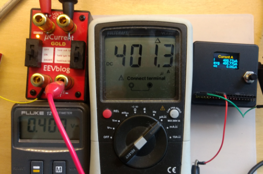
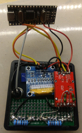
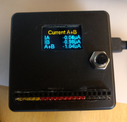
Double Micro (nano) Ampere meter
-
Looks great @AWI!
-
I need this! Please publish instructions
-
Awsome!
I'd like to compare your impressive array of measurement devices against my Agilent U1273A. Actually to decide if I need a µCurrent.... Maybe in an upcoming meetup in NL or BE this summer?
-
That looks impressive. I'll be waiting for the instructions too
-
Wow, that looks nice, I'm stucked with my multimeter and couldn't find the parts avaiable for delivery here to build a µcurrent gold.
Please publish the build instructions !
(Maybe if you could give use the BOM first, then you'll have plenty of time to publish build instruction before we get delivered ;))
-
@DavidZH Impressive only by numbers I am prepared to trade my µCurrent for the Agilent
A meetup sounds good..any specific plans yet?
-
There it is Micro (nano) ampere meter (double). I need to add a schematic drawing. Any suggestions/ questions are welcome.
-
Why all those headers are needed?
-
Parts ordered
-
@gohan As mentioned in the description: I use it as a "patch panel" to distribute the power and ground to different devices. Wiring tends to get messy on my workbench...
Not mine but similar
-
Oh ok, you use it like an integrated breadboard
-
@AWI - did you steal my image on my workbench j/k.
We need to revive the old workbench topic again!
-
Are resistor needed with a tight tolerance or else?
-
@gohan No special tolerance resistors needed. The only reason for choosing metal film resistors is that their temperature coefficient is better than carbon types (typical 50ppm/°C compared to 200-500ppm/°C).
As you will be calibrating the circuit you can choose from a large range (0.1 Ohm - 100 Ohm) for the shunt. This will only influence the burden voltage / sensitivity and range (Ohm's laws).
-
@AWI Lemme think about that..... Uuuuuhm. no...
I have no plans for a meetup. Lacking a proper venue for such a thing. Unfortunately.
-
If there is some interest I will try to publish a decent built instruction on Openhardware.io.
I'm interested.
-
@NeverDie said in Double Micro (nano) Ampere meter:
I'm interested.
In case you haven't seen it, it's here :
https://forum.mysensors.org/topic/6723/micro-nano-ampere-meter-double/5
-
@Nca78 said in Double Micro (nano) Ampere meter:
@NeverDie said in Double Micro (nano) Ampere meter:
I'm interested.
In case you haven't seen it, it's here :
https://forum.mysensors.org/topic/6723/micro-nano-ampere-meter-double/5Thanks! It looks a bit complicated to me. I've used one of these breakout boards (https://www.amazon.com/gp/product/B00OPVBEQO/ref=oh_aui_search_detailpage?ie=UTF8&psc=1) as a way to measure 24-bit voltage on capacitors, and it works really well. As you can perhaps tell from the photo:
the chip is fairly simple to use. What I especially liked is that there was already a demo arduino sketch for interfacing with it. That was a real time saver. If I were to build something, I might try that first, if only because it seems like it might be easier (though perhaps, in part, because I'm already comfortable with it). Would using it in conjunction with a sense resistor be all it would take to make an accurate, high resolution current sensor?
-
@NeverDie that one would work as well. Maybe harder to get and a little more pricy
-
@NeverDie said in Double Micro (nano) Ampere meter:
It looks a bit complicated to me
btw. Which part looks complicated? It's just a few resistors attached to an ADC board (and sketch ready) I am curious on how you can build something simpler with the ADS1220 (which seems to be a better ADC if you are able to find it somewhere ;-))
-
It sounds like I was mistaken then. In my quick read I thought that I had to implement the entire schematic, not just add a couple of resistors to a pre-made breakout board. I suppose if the schematic were more of a block diagram, that might be clearer for other future readers to quickly grasp, or maybe it's just me.
Why would the ADS1220 be a better ADC? I really haven't looked into doing a comparison. I bought the breakout board that I pictured above from Amazon , but I see that it's out of stock now. I believe the company which made it is in India. I seem to recall that it's open source, so there's always that I suppose. I didn't mind ringing the till for the maker: it was all pre-made, it did what I needed at the time (which was watching in real-time the voltage leakage from supercapacitors that I was testing), it was available with free Amazon Prime delivery, and I wanted something sooner rather than later. So, it fit what I needed at the time. Most of those reasons relate to rapid availability though rather than technical reasons.
-
OK, I received an HX711 and have partially hooked it up. I have it connected to an UNO and powered by the 3.3v pin. I also have AWI's sketch running on the UNO. I haven't yet connected a OLED screen to it, so at the moment I'm just looking at the output of the serial consol, which gives a running output of "average" and "spread". I have 10mv connected between A+ and A- to just to see what it will do.
Looking at the code, it looks as though the button (A2) is normally pulled high. Is the button supposed to be connected to GND through a 330 ohm resistor? I don't see any schematic with a button on it.
-
@NeverDie the sketch uses the internal pullup:
Button myBtn(buttonPin, true, true, 40); // Declare the button( pin, pullup, invert, debounce ms)
-
@mfalkvidd said in Double Micro (nano) Ampere meter:
@NeverDie the sketch uses the internal pullup:
Button myBtn(buttonPin, true, true, 40); // Declare the button( pin, pullup, invert, debounce ms)
Right. So that's one leg of the button. Is the other leg connected to GND through a 330ohm resistor? Or....?
-
@NeverDie sorry. Of course you knew that already
I found this in the instructions:
Solder the Button to A2 and Gnd of the nano
I guess that means the other leg is connected directly to GND, no resistor is involved there?
-
Thanks. I'll do that then.
Regardless, I must be doing something wrong, because I'm feeding it 9.9mv (see photo)
across A+ and A- from a voltage divider powered by 2xAA batteries, but it's showing zero current. Shouldn't it be showing 9900ua instead?[I alsoi tried sending it 99uv instead, but it still reads zero]
-
So, here it is with the button and with 99uv applied.
Button mechanics works fine, but it keeps registering zero as the uA. Isn't it 1uv=1ua? So, shouldn't it be reading 99ua? Or am I (quite probably) misunderstanding something?The HX711 I'm using is a clone of the Sparkfun one.
-
I added in the 0.1uF cap across A+ and A-, but that made no difference.
What's odd is that if I run the sparkfun scale code, it does in fact detect voltage (and converts it to pounds). Hmm.. Sounds like maybe it's not reading the right datapins. I'll check that next.
-
Yup. That was my error. I had initially wired it using the sparkfun directions for the initial test. Sparkfun wired the DAT and CLK pins to different arduino pins. When I made the change to AWI's selections, it now works.
-
By the way, there was a similar project posted on the eevblog by a guy named quantumvolt:
https://www.eevblog.com/forum/projects/ppmgeek!-5-5-digit-dvm-volt-ref-cal-(for-arduino-or-any-uc-w-spi)/
One of the things that they eventually noticed and talked about was that quite a bit of noise came in over the usb. Not sure if that applies only to usb's connected to computers for power, or whether it may apply to other sources as well. Anyhow, just thought I'd mention it in case anyone here is using that and wants to drop their noise level.Also, although I'm no expert, I would guess this project might (?) benefit from a PCB implementation, because, in general, it seems like the shorter the connections, the lower the noise. Of course, please just take that as constructive feedback. No criticism intended. I think it may also be why Dave Jones chose to power his uCurrent from a button cell directly attached to his PCB: he wanted the power lines to be as short as possible.
Thanks again for posting the project!
-
@AWI do you think that logging reading to SD card could be a useful addition? (in case you want to monitor something for a longer time)
-
@gohan said in Double Micro (nano) Ampere meter:
@AWI do you think that logging reading to SD card could be a useful addition? (in case you want to monitor something for a longer time)
Yeah, but then you'd probably also want an RTC to go with it. There are already shields for both of those, though, so it's probably better to keep the project simple. Since I'm interested in solar charging current, I'll probably monitor wirelessly and do my logging that way. It's more fun to see stuff graphed in real time.
-
The refresh rate is really slow: a lot slower than 100ms described in
https://www.openhardware.io/view/380/Micro-nano-ampere-meter-double
where in the introduction it says, "~100ms update rate to be able to 'see' power fluctuations (like radio communication)". What do I need to change to get that?It matters less, but response to button pushes is also very slow. Has anyone devised a fix for that?
Rather than re-invent the wheel, I thought I'd ask first.
I did try increasing the sample rate by solder bridging the "RATE" solder pads on the back:
I'm not sure, but that may have helped speed things up a bit. It's still very slow updating though: nearly 7 seconds between screen updates.Anyhow, current consumption during normal operation is something < 1.5mA, according to the datasheet. So, for my purposes (admittedly a bit different than the OP's), I need to get it powered up, take a reading, and then power down again as quickly as possible. The datasheet says the powerdown drain for the HX711 is <1ua.
-
I have the same problem, I don't have a jumper on my HX711 board so I soldered directly the pin of the IC with a small wire.
It has clearly improved things, but it's still slow so I will try to reduce number of samples and if it's not enough switch to TTP223 touch buttons in toggle mode, one to reset, one to change screen, so I will never miss a press.
-
@NeverDie @Nca78 a lot going on here Nice to see that my afternoon project sparked creativity.
I started this to be a datalogger for remote monitoring of MySensors node power consumption. During the run changed my mind and it turned out to be this which fits my needs. But all options are still open..
The converter has a max sample rate of 80Hz which was default on the board I used. I balanced accuracy and readability by applying sample averaging. This averages out much of the noise from USB source etc.
The sparkfun boards are probably designed a little different and don't have the shield which helps to keep out noise.
To increase speed you can change the amount of averaging (number of readings per sample)
To get a better response for the button the way is to go for non blocking (averaging) readings of the Adc. The library is very basic so that would be the best place to start.
-
Seems like adding a larger cap on the ADC input would be an alternate way to average the readings, and require fewer ADC cycles. I'll give that a try.
I have the HX711 with the metal can on order, but only China had it, so it will take a while to get here. If anyone gets desperate, I suppose they could make their own metal enclosure and connect it to the "yellow" pin, which is there for that purpose. Unfortunately, noise will still leak in over the wiring, so I don't have high hopes it will make much difference.
-
I got mine hx711 with shield, I only need to buy a 2-3 hours extension for the daily 24 hours as it seems they are not enough lately
-
I've concluded that the ADS1220 is, for now, a better fit for my needs. If I have it sample at 20SPS and throw out the first sample, then all subsequent samples are within less than 1ua of the final number. That's from a sloppy dupont wiring on a breadboard, so more proper and shorter connections on a PCB might be even better. Regardless, for my immediate purposes, repeat-ability at <1ua is good enough. The current consumption is less, and I get my answer much faster than with the HX711.
Just to be clear, I'm not here to rain on the HX711's parade. I'm mentioning the above only in case anyone else has needs similar to mine. I may revisit the HX711 later, after I receive the metal can version from China. Meanwhile, I look forward to following whatever progress people make with it.
-
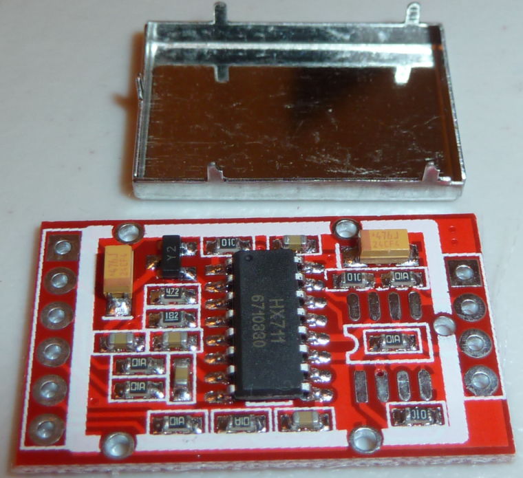
I received the red HX711 board with the metal can. What does the J1 solder jumper on the back do?
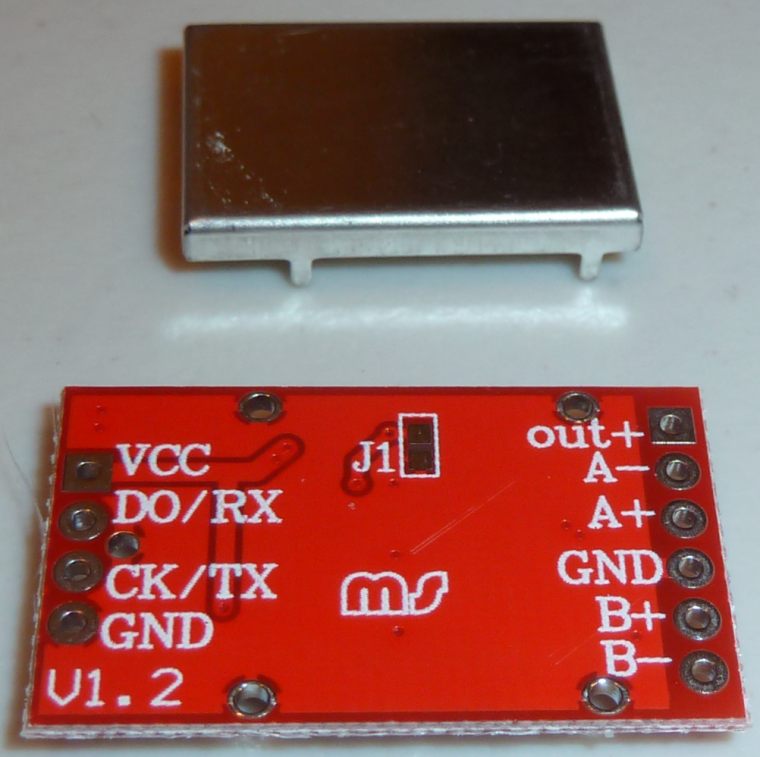
Also, any mods I should make before attaching the metal lid (to, for example, speed up the sample rate?)
-
I threw together this wireless node for measuring and reporting sub-milliamp currents using an ADS1220. I hope to do the same now with the HX711. Since it's auxillary to the circuit being tested, the extra measurement time of the HX711 won't matter so much.
-
The reference PCB in the HX711 datasheet (https://cdn.sparkfun.com/datasheets/Sensors/ForceFlex/hx711_english.pdf) does not show a J1. Whatever it is, AWI did not solder bridge his J1, at least not in the photographed version he posted.
-
Hi guyes!
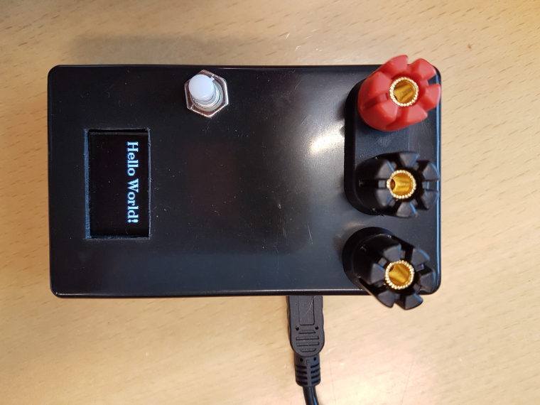
Finished my device yesterday but to my surprise the display is blank all the time when running the "Double Micro Ampere meter" sketch. I tested the display with the "Hello World!" example from the Lib and it seems to work. What might I be doing wrong?
-
Seems like it cannot communicate with the HX711 so it gets stuck at "scale.begin"
Need to look in to that. I'm using A3 and A6 for the dout and sck this should work right? Or do I have to use A0 and A1?
-
Seems I can't use A6 since A6 and A7 are "Analog Exclusively Pins". Darn, need to disassemble and correct...
-
Looking great !
@NeverDie check the pinout of the IC on the datasheet and check if the jumper is connected to RATE pin on one side.
-
@Nca78 Seems to be working now I should not have deviated from the instructions
-
The banana plugs (is that what they are?) look very smart.
-
@Nca78 said in Double Micro (nano) Ampere meter:
@NeverDie check the pinout of the IC on the datasheet and check if the jumper is connected to RATE pin on one side.
Yup, it is. Thanks! Another mystery solved.
-
@NeverDie said in Double Micro (nano) Ampere meter:
@Nca78 said in Double Micro (nano) Ampere meter:
@NeverDie check the pinout of the IC on the datasheet and check if the jumper is connected to RATE pin on one side.
Yup, it is. Thanks! Another mystery solved.
Then you might have to solder it if you're not ready to very very patient
-
@Nca78 said in Double Micro (nano) Ampere meter:
I have the same problem, I don't have a jumper on my HX711 board so I soldered directly the pin of the IC with a small wire.
It has clearly improved things, but it's still slow so I will try to reduce number of samples and if it's not enough switch to TTP223 touch buttons in toggle mode, one to reset, one to change screen, so I will never miss a press.I just now ordered these:
https://www.aliexpress.com/item/10PCS-LOT-Touch-Sensor-Jog-type-touch-module-capacitive-touch-buttons/32416625224.html?spm=2114.13010608.0.0.IOBe1p
Is it the kind you're using? I guess the solder bridge determines whether or not it latches?
-
@NeverDie said in Double Micro (nano) Ampere meter:
@Nca78 said in Double Micro (nano) Ampere meter:
I have the same problem, I don't have a jumper on my HX711 board so I soldered directly the pin of the IC with a small wire.
It has clearly improved things, but it's still slow so I will try to reduce number of samples and if it's not enough switch to TTP223 touch buttons in toggle mode, one to reset, one to change screen, so I will never miss a press.I just now ordered these:
https://www.aliexpress.com/item/10PCS-LOT-Touch-Sensor-Jog-type-touch-module-capacitive-touch-buttons/32416625224.html?spm=2114.13010608.0.0.IOBe1p
Is it the kind you're using? I guess the solder bridge determines whether or not it latches?Not using them yet. But using them for other boards and the "big" solder bridge in the corner is for adding a capacitor to set sensitivity (up to 50pF, the higher the less sensitive it is so by default it's at max sensitivity). Toggle mode is set using the the "B" tiny jumper in the middle of the board.
Jumper A is for AHLB pin, it inverses the logic level of the output.
-
Once I decided to power the HX711 externally rather than through the solar node, it has turned out to be a nice little current monitor. Typical charging currents for indoor solar nodes that are far from windows is only around 50ua, and the HX711 seems good enough for monitoring charge currents at around that amount.
Thanks @AWI for posting the project!