Another simple (No SMT) relay actuator
-
Since i dont think humans should solder SMT devices
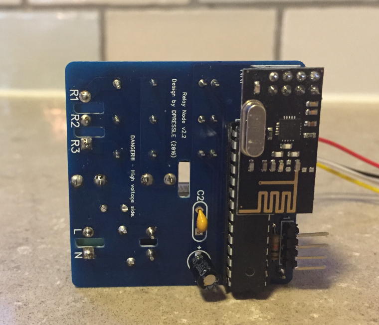
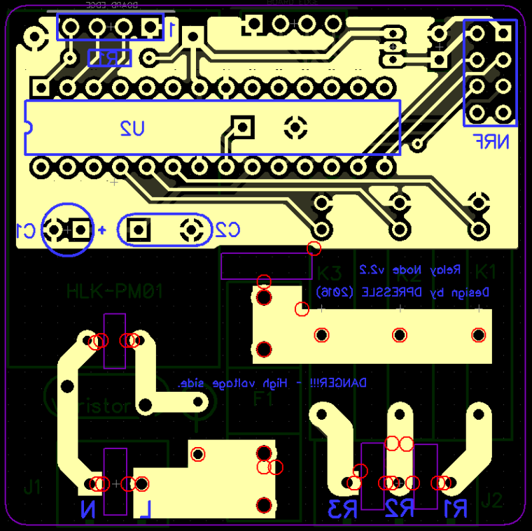
 i made this nice little non SMT board with 3 SSR relays, Hi-Link power supply, atmega328P and separated fuses for PSU and load, in a 5X5 CM board.
So far its working great, i did not put a temp fuse in the design mainly because i dont see any commercial in wall units using one, so for me i think its safe enough to not use it.
I would appreciate your comments on it, Thanks.
Main goals are:- No SMT
- 5X5 CM board
- Safe for in wall use
- Simple and cheep
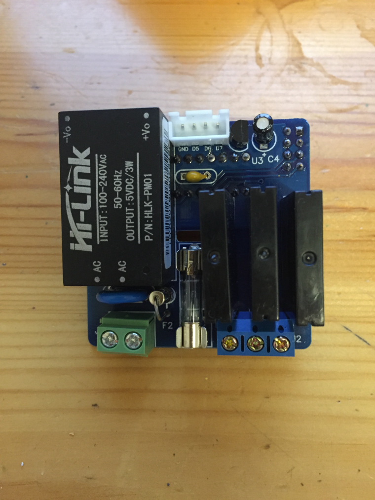
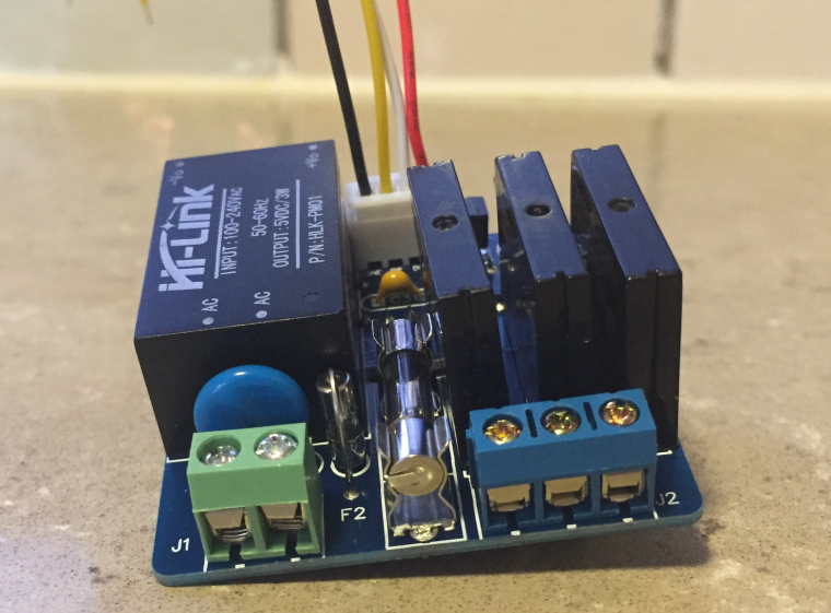
Top side design:
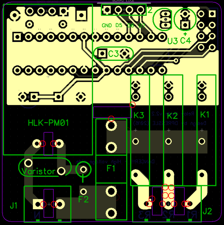
Bottom side design:
-
Thanks for the comments, wow what a great forum we have here

-
-
@dpressle This is an impressive unit!
I love the neatness and non SMT. Fantastic.
Do you have an idea of the pricing all up?
-
Thanks, should be under 10USD in parts.
BTW, same design but for roller shutter is on the way
-
Hello,
nice design with some care for safety !
If possible, I would suggest to connect A4/A5 to the connector, so it would be possible to use (for example) an i2c touchpad, to command the 3 relays and more, for example mpr121 can manage a mix of touchpads and leds. In case of managing leds, of course a Vcc connector would be necessary too as the last input pins would not provide enough current.
Analog pins A0-A5 can be used as digital pins if needed so it could still work as you designed it at the moment with physical switches.On thing that is annoying me also with some designs, is that when you want to use in ceiling to connect directly to ligh bulbs, you need to use connectors/wago to "duplicate" neutral because the board only provides live. If possible you should move J1 to the right, and put holes to add extra 2x connector on the left if people want to have neutral without external connectors, it will give a much cleaner result when connected instead of a mess of wires. I think it's possible to do it if you move the varistor to the left, and change orientation of F2.
-
@Nca78 Thanks for the tips, i understand what you are saying about the neutral and it is a good idea, my intentions were to put it in the switch box and not in the light fixture itself, but i might add it to the next release.
-
@dpressle nice!
-
@breimann Thanks, does any one want link to dirtypcbs?
-
Hi, dpressle. Thanks for your work?
One Question. Can i connect a normal light switch to it? So that i can turn on the lights with the switch and this node?
-
@artipi Sure you can that is the whole point of the D5, D6, D7 connection.
You just need to take the GND and each of these digital inputs and connect them to the switch (NO high voltage in the switch only GND and digital input), each one of then controls one relay.
-
@dpressle said in Another simple (No SMT) relay actuator:
@breimann Thanks, does any one want link to dirtypcbs?
Hi!
Yes, please send links, really good design!
Regards Rickard
-
-
-
Where can you find the code?
-
@MLs Its in the OpenHardware page see the Source Code tab:
OpenHardwareNote its intended to work with "Home Assistant" HA, some depending on your controller some changes might be needed.
-
-
@MLs Yes sure
-
-
-
-
@MLs yes it does.
-
Feeling a bit confused how do you know that a bootloader uses the internal clock?
Because I used another bootloader after installing your card, I did not get the Atmega circuit to run. But if I used this bootloader, I started the Atmega circuit and everything worked.But what makes the internal clock in used?
I use a UNO when I'm burning bootloader and do not know if you can change fuses and clock option.
-
@MLs I think i lost you there, if there is no external osc how would it work? it is clear (at list to me) that its using the internal clock. Maybe you mean the f_cpu parameter? it is in the board text file.
I also use a nano to burn the bootloader, you can set the fuses as you wish in the boards page exactly as the link you gave is describing.
If you dont care of OTA you can use any other bootloader (like optiboot), i did it as well with this board.
I want to help you more but i need more info and pictures of your exact setup and files, can you share it?
Also some times your atmega328p-pu comes with 16Mhz bootloader pre-installed so you do need to set it up with 16Mhz osc for the first 8Mhz bootloader burn, after that you can remove it.
-
@dpressle
Ok first, I have to say that I have no problem getting your project to work. It connects directly to HA. What I get a little confused about is that according to the link I linked to it says.Be sure to select "ATmega328 on a breadboard (8 MHz internal clock)" when burning the bootloader.(If you select the wrong item and configure the microcontroller to use an external clock, it won't work unless you connect one.)
And as I interpret your post, you can take whatever bootloader you want (8 MHz).
And if I understand you right now, all settings iis n the board.txt file?//Mattias
-
@MLs When i said "what ever bootloader you want" i meant MYS OTA bootloader or optiboot or breadboard bootloader etc.
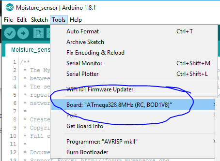
They all have 8 Mhz version.In any way this is my boards.txt settings if it helps:
MYSBL13.name=ATmega328 8MHz (RC, BOD1V8)MYSBL13.upload.maximum_size=30720
MYSBL13.upload.maximum_data_size=2048
MYSBL13.upload.speed=38400
MYSBL13.upload.tool=arduino:avrdude
MYSBL13.upload.protocol=arduinoMYSBL13.bootloader.low_fuses=0xE2
MYSBL13.bootloader.high_fuses=0xDA
MYSBL13.bootloader.extended_fuses=0xfeMYSBL13.bootloader.file=MYSBootloader/MYSBL13pre_atmega328_8Mhz.hex
MYSBL13.bootloader.unlock_bits=0x3F
MYSBL13.bootloader.lock_bits=0x0F
MYSBL13.bootloader.tool=arduino:avrdudeMYSBL13.build.mcu=atmega328p
MYSBL13.build.f_cpu=8000000L
MYSBL13.build.core=arduino:arduino
MYSBL13.build.variant=arduino:standardThen in the IDE i select:
-
I do not get Atmel to run with Mysbootloader 8MHz.
Seems like it does not use the internal clock
Also tried to put your text into the board.txt file without any difference.
But if I use the bottloader ATmega328 on a breadboard (8 MHz internal clock it work.
-
@MLs as i said, i can only try to help if you get me more information about your environment and pictures and then i can compare it to mine.
-
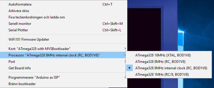
##############################################################

MYSBL13.name=ATmega328 with MYSBootloader

MYSBL13.upload.tool=avrdude
MYSBL13.upload.protocol=arduino

MYSBL13.bootloader.tool=avrdude
MYSBL13.bootloader.unlock_bits=0x3F
MYSBL13.bootloader.lock_bits=0x0F

MYSBL13.build.mcu=atmega328p
MYSBL13.build.board=AVR_PRO
MYSBL13.build.core=arduino
MYSBL13.build.variant=standard

## Arduino with MYSBootloader 1.3pre
## -------------------------------------------------
MYSBL13.menu.cpu.16MHzatmega328=ATmega328 16MHz (XTAL, BOD1V8)
MYSBL13.menu.cpu.16MHzatmega328.upload.maximum_size=30720
MYSBL13.menu.cpu.16MHzatmega328.upload.maximum_data_size=2048
MYSBL13.menu.cpu.16MHzatmega328.upload.speed=115200
MYSBL13.menu.cpu.16MHzatmega328.bootloader.low_fuses=0xFF
MYSBL13.menu.cpu.16MHzatmega328.bootloader.high_fuses=0xDA
MYSBL13.menu.cpu.16MHzatmega328.bootloader.extended_fuses=0x06
MYSBL13.menu.cpu.16MHzatmega328.bootloader.file=MYSBootloader/MYSBL13pre_atmega328_16Mhz.hex
MYSBL13.menu.cpu.16MHzatmega328.build.mcu=atmega328p
MYSBL13.menu.cpu.16MHzatmega328.build.f_cpu=16000000L

MYSBL13.menu.cpu.8MHzatmega328=ATmega328 8MHz (RC, BOD1V8)
MYSBL13.menu.cpu.8MHzatmega328.upload.maximum_size=30720
MYSBL13.menu.cpu.8MHzatmega328.upload.maximum_data_size=2048
MYSBL13.menu.cpu.8MHzatmega328.upload.speed=38400
MYSBL13.menu.cpu.8MHzatmega328.bootloader.low_fuses=0xE2
MYSBL13.menu.cpu.8MHzatmega328.bootloader.high_fuses=0xDA
MYSBL13.menu.cpu.8MHzatmega328.bootloader.extended_fuses=0x06
MYSBL13.menu.cpu.8MHzatmega328.bootloader.file=MYSBootloader/MYSBL13pre_atmega328_8Mhz.hex
MYSBL13.menu.cpu.8MHzatmega328.build.mcu=atmega328p
MYSBL13.menu.cpu.8MHzatmega328.build.f_cpu=8000000L

############# DO NOT WORK INTERNAL CLOCK #####################

MYSBL13.menu.cpu.8MHzinternalclockatmega328=ATmega328 8MHz internal clock (RC, BOD1V8)
MYSBL13.menu.cpu.8MHzinternalclockatmega328.upload.maximum_size=30720
MYSBL13.menu.cpu.8MHzinternalclockatmega328.upload.maximum_data_size=2048
MYSBL13.menu.cpu.8MHzinternalclockatmega328.upload.speed=38400
MYSBL13.menu.cpu.8MHzinternalclockatmega328.upload.tool=arduino:avrdude
MYSBL13.menu.cpu.8MHzinternalclockatmega328.upload.protocol=arduino
MYSBL13.menu.cpu.8MHzinternalclockatmega328.bootloader.low_fuses=0xE2
MYSBL13.menu.cpu.8MHzinternalclockatmega328.bootloader.high_fuses=0xDA
MYSBL13.menu.cpu.8MHzinternalclockatmega328.bootloader.extended_fuses=0xfe
MYSBL13.menu.cpu.8MHzinternalclockatmega328.bootloader.file=breadboard/MYSBL13pre_atmega328_8Mhz.hex
MYSBL13.menu.cpu.8MHzinternalclockatmega328.bootloader.unlock_bits=0x3F
MYSBL13.menu.cpu.8MHzinternalclockatmega328.bootloader.lock_bits=0x0F
MYSBL13.menu.cpu.8MHzinternalclockatmega328.bootloader.tool=arduino:avrdude

MYSBL13.menu.cpu.8MHzinternalclockatmega328.build.mcu=atmega328p
MYSBL13.menu.cpu.8MHzinternalclockatmega328.build.f_cpu=8000000L
MYSBL13.menu.cpu.8MHzinternalclockatmega328.build.core=arduino:arduino
MYSBL13.menu.cpu.8MHzinternalclockatmega328.build.variant=arduino:standard
MYSBL13.menu.cpu.1MHzatmega328=ATmega328 1MHz (RC/8, BOD1V8)
MYSBL13.menu.cpu.1MHzatmega328.upload.maximum_size=30720
MYSBL13.menu.cpu.1MHzatmega328.upload.maximum_data_size=2048
MYSBL13.menu.cpu.1MHzatmega328.upload.speed=9600
MYSBL13.menu.cpu.1MHzatmega328.bootloader.low_fuses=0x62
MYSBL13.menu.cpu.1MHzatmega328.bootloader.high_fuses=0xDA
MYSBL13.menu.cpu.1MHzatmega328.bootloader.extended_fuses=0x06
MYSBL13.menu.cpu.1MHzatmega328.bootloader.file=MYSBootloader/MYSBL13pre_atmega328_1Mhz.hex
MYSBL13.menu.cpu.1MHzatmega328.build.mcu=atmega328p
MYSBL13.menu.cpu.1MHzatmega328.build.f_cpu=1000000L

##############################################################```
-
@MLs try to first upload the burning sketch to the nano (even if its already uploaded) and then burn the bootloader.
What set up do you have, how the nano is connected to the atmega?
What error do you get when bootloader burn fails?
-
The problem is not to burn bootloader. The problem I think is that the Mysbootloader does not use internal clock.
Therefore, I asked you how to know how a bootloader uses an external clock or internal clock.
And because you had a bootloader for OTA and internal clock, 8MHz I wanted you to send it to me.
-
@MLs I am completely lost here, you said "I do not get Atmel to run with Mysbootloader 8MHz." and now you are asking "how to know how a bootloader uses an external clock or internal clock" how can you say its not working and then ask me how to know that its working?
To conclude this, if you successfully burn the 8Mhz Mysbootloader and the board is working then it is working with 8Mhz it cannot be working on 16Mhz because there is no external osc, its not 1Mhz because of the fuses etc.
-
@MLs said in Another simple (No SMT) relay actuator:
Feeling a bit confused how do you know that a bootloader uses the internal clock?
Because I used another bootloader after installing your card, I did not get the Atmega circuit to run. But if I used this bootloader, I started the Atmega circuit and everything worked.But what makes the internal clock in used?
I use a UNO when I'm burning bootloader and do not know if you can change fuses and clock option.If you use a bootloader that uses an external clock, you will not get the Atmega circuit to run. If I understand everything right.
No if I'm burning 8MHz Mysbootloader, the Atmega circuit does not start.
But instead, I use this bootloader (ATmega328 on a 8 MHz internal clock) and I get the Atmega circuit to run, but without OTA.
-
@MLs said in Another simple (No SMT) relay actuator:
@MLs said in Another simple (No SMT) relay actuator:
Feeling a bit confused how do you know that a bootloader uses the internal clock?
Because I used another bootloader after installing your card, I did not get the Atmega circuit to run. But if I used this bootloader, I started the Atmega circuit and everything worked.But what makes the internal clock in used?
I use a UNO when I'm burning bootloader and do not know if you can change fuses and clock option.If you use a bootloader that uses an external clock, you will not get the Atmega circuit to run. If I understand everything right.
No if I'm burning 8MHz Mysbootloader, the Atmega circuit does not start.
But instead, I use this bootloader (ATmega328 on a 8 MHz internal clock) and I get the Atmega circuit to run, but without OTA.
Therefore, I asked you how to know how a bootloader uses an external clock or internal clock.
-
@MLs You said before "The problem is not to burn bootloader."
and now you are saying "No if I'm burning 8MHz Mysbootloader, the Atmega circuit does not start."I am asking again, are you able to successfully burn and run Mysbootloader 8Mhz or not?
-
I can burn Mysbootloader yes.
But the Atmega circuit does not start.
The problem I think is that Mysbootloader does not use the internal clockAnd because you said you had a bootloader for OTA and internal clock, 8MHz I wanted you to send it to me.
Then there would have been no problem, I think.
-
@MLs i use what you use, Mysbotloader 1.3pre, as i said in one of the first messages, you dont need me to send it to you you can (and did) download it from here.
This is why i think you are doing something wrong or have wrong settings.
-
And my settings are seen in previous posts.
But this does not lead to anything so I finish this now.
-
Is this setup to take a maximum 2 amp load? Plenty for a lighting circuit, just curious in case someone tries to use it on a switched outlet circuit etc.
J1 is power feed and J2 are the three switched outputs right with the wall switch connected using D5 - D6 - D7 right?
-
@Shaun-Storbakken It was designed with the idea of controlling 3 different loads of up to 2 Amp each, lightning, switches etc.
The D-5,6,7 are for manual switching and they will (if you use my code) control the 3 relays respectively, J1 is power input 110-220V, please note that you should pay attention to the polarity and connect line wire to the right of J1 (otherwise you will end up switching natural to the load), J2 is AC output where each one is different relay, so you have 3 X 110-220V outputs of max 2 A each.I hope it was helpful, please let me know if you need further help.
-
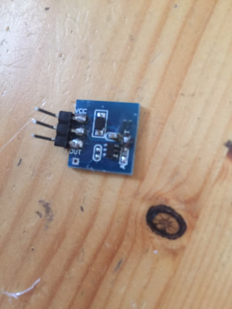
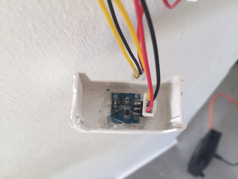
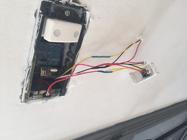
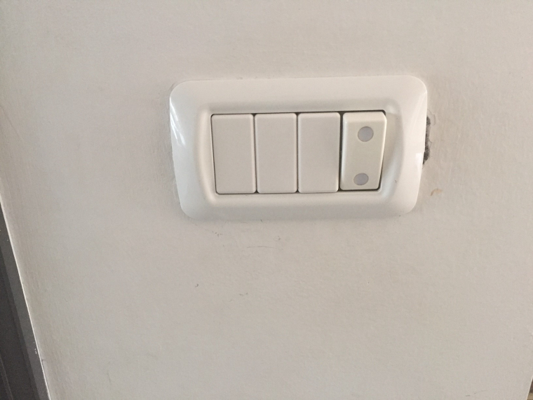
Small update, i connected touch switches to the board instead of mechanical switches.
where i live we are using gwiss switches and when the board is in the box there is not much room for mechanical switches as they are too deep, so i took some blanks that are used to cover unused switch hols and added touch switch to it, see the pictures below:
-
@dpressle Nice job!