6/8 Buttons battery remote node
-
I would like to make a 6 or 8 buttons remote control (to control some lights and scenes) with NRF24 or RFM69 and be a battery powered node. Is there a clever way to handle interrupts on all the pins besides the usual 2 and 3?
-
You can :
- use another IC that is not so cheap about external interrupts (ex: nrf5)
- connect each button to pin 3 through a diode so your board will wake up, then check each input pin to know which button is pressed
- use pin change interrupt, it works but you need to write your own sleep method as it's not in the options of the MySensors sleep
- use an extender ic (for example sx150x but there are cheaper and easier to solder options) or a touch ic (for example mpr121) and use their interrupt pin to wake up your board, then retrieve data through I2C
-
@nca78 said in 6/8 Buttons battery remote node:
connect each button to pin 3 through a diode so your board will wake up, then check each input pin to know which button is pressed
I had the same thought, I just wanted to ask for other viable options. How is the power usage of the mpr121?
-
@gohan said in 6/8 Buttons battery remote node:
@nca78 said in 6/8 Buttons battery remote node:
connect each button to pin 3 through a diode so your board will wake up, then check each input pin to know which button is pressed
I had the same thought, I just wanted to ask for other viable options. How is the power usage of the mpr121?
Somewhere around 20uA.
-
I wonder if this would do what Gohan has in mind?
https://www.aliexpress.com/item/Button-Keypad-3x4-module/32530917534.html?spm=2114.10010108.0.0.2d82a4e4IC03UP&traffic_analysisId=recommend_2049_1_83259_iswiall&scm=1007.12908.83259.0&pvid=19937069-0349-4cc8-8b2a-ca440c3537da&tpp=1
Looks as though it needs just one analog pin to read the voltage and thereby infer which button was pressed. With luck, maybe all the voltages would be high enough to trigger the interrupt.
-
Here it is notionally for 4 buttons:
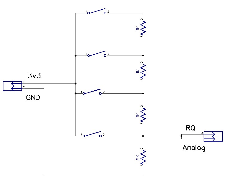
It's a voltage divider. Structured like this, it could trigger the IRQ pin when a button is pushed, and the analog pin could read the voltage to determine which button it was.
-
By clever resistor selection, you can even shave a few resistors off the design:
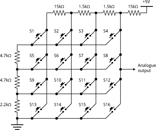
-
@neverdie I know, it is similar to the arduino examples for the classic flat numeric keypad, the problem would be how to trigger the interrupt to wake the mcu.
-
@gohan said in 6/8 Buttons battery remote node:
the problem would be how to trigger the interrupt to wake the mcu.
What problem? You trigger on the rising edge.
The other benefit is that it consumes no power unless a button is pushed.
-
On analog pin?
-
Well, on an arduino, you could wire it to both the IRQ pin and an analog pin (see above schematic). On an nRF52832, you'd need only one pin.
-
Would it still be able to trigger interrupt even with all those resistors?
-
@gohan said in 6/8 Buttons battery remote node:
Would it still be able to trigger interrupt even with all those resistors?
Try it. I don't see a problem with it, but if it were a problem, you'd just reduce all the resistor values proportionately.
-
The nice thing is that since you'd be measuring the voltage relative to the voltage powering your arduino/mcu, even if the battery voltage were to decrease, you'd still get the correct value for the button pressed.
-
@neverdie said in 6/8 Buttons battery remote node:
On an nRF52832, you'd need only one pin.
Slightly off topic question. On the nRF5's, can any pin act as an interrupt?
-
@dbemowsk said in 6/8 Buttons battery remote node:
@neverdie said in 6/8 Buttons battery remote node:
On an nRF52832, you'd need only one pin.
Slightly off topic question. On the nRF5's, can any pin act as an interrupt?
IIRC, any GPIO can. I can't think of any exceptions. So, notionally, you would wake from the interrupt pin, then change it to be an analog pin and read the voltage from that.
-
@neverdie said in 6/8 Buttons battery remote node:
Here it is notionally for 4 buttons:

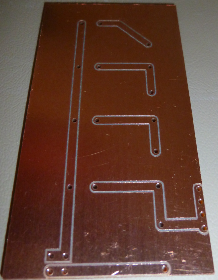
It's a voltage divider. Structured like this, it could trigger the IRQ pin when a button is pushed, and the analog pin could read the voltage to determine which button it was.I made a custom PCB to test the concept:
-
Tomorrow I'll try to bring out the arduino numeric keypad and an old sketch I used with it and see what I can do
-
@gohan said in 6/8 Buttons battery remote node:
Tomorrow I'll try to bring out the arduino numeric keypad and an old sketch I used with it and see what I can do
Cool! I didn't know there was an official Arduino keypad.
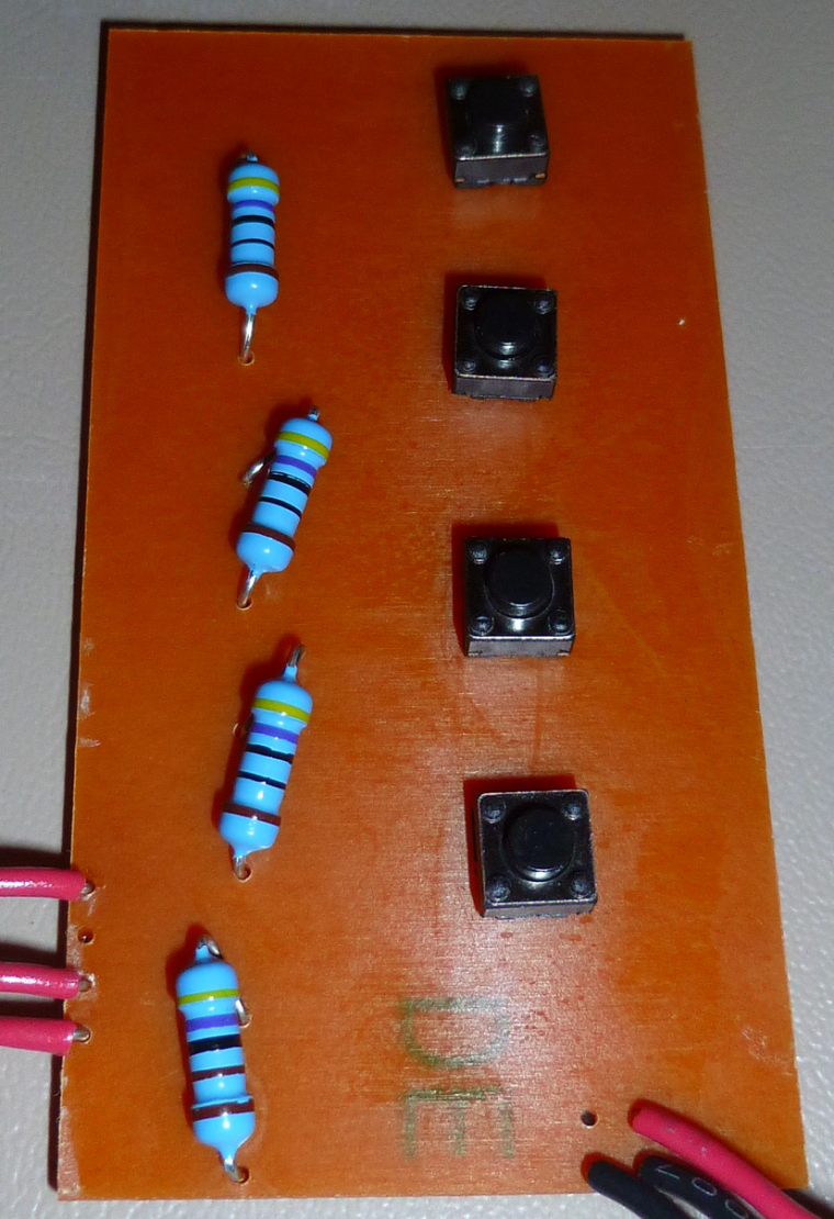
Here's mine:
-
It works. Connecting the output wires to A0 and D3, and running this script:
#include <avr/sleep.h>

void wake ()
{
  // cancel sleep as a precaution
  sleep_disable();
  // precautionary while we do other stuff
  detachInterrupt (1);
}  // end of wake

void setup() {
  pinMode(A0,INPUT);
  Serial.begin(115200);
  Serial.println("Starting...");
  Serial.flush();

}

void loop() {
  uint16_t voltage;

  set_sleep_mode (SLEEP_MODE_PWR_DOWN);
  sleep_enable();

  // Do not interrupt before we go to sleep, or the
  // ISR will detach interrupts and we won't wake.
  noInterrupts ();

  // will be called when pin D2 goes low
  attachInterrupt (1, wake, RISING);  //pin D3

  EIFR = bit (INTF1);  // clear flag for interrupt 1

  // turn off brown-out enable in software
  // BODS must be set to one and BODSE must be set to zero within four clock cycles
  MCUCR = bit (BODS) | bit (BODSE);
  // The BODS bit is automatically cleared after three clock cycles
  MCUCR = bit (BODS);

  // We are guaranteed that the sleep_cpu call will be done
  // as the processor executes the next instruction after
  // interrupts are turned on.
  interrupts ();  // one cycle
  sleep_cpu ();   // one cycle

  delay(100);  //debounce the button
  voltage=analogRead(A0);
  if (voltage>0) {
    Serial.println(voltage);
    Serial.flush();
  }
}
on a 3.3v Arduino pro mini yields these values for each of the four buttons:
Starting...
1023
930
852
787
The pro mini sleeps until one of the buttons gets pressed, then it wakes up, reads the value, displays the value, and then goes back to sleep.

-
It * might* get a little hairy though if running at 1.8v and you've got a lot of buttons to disambiguate and you still want to wake up on any button press. According to Table 32-2 of the atmega328p datasheet, the minimum threshold for input HIGH if running at vcc=1.8v-2.4v is 0.7Vcc. So, at the limit, that is 0.7*1.8v=1.26v. So, if n is the number of buttons, you need to disambiguate, then in a perfect world 0.54/(n-1) volts separates each button press. So, if say 12 buttons, that is 0.54/11=0.049 volts. Well, let's see: resolution is 1.8v/1023=0.0018v.
Hmm... Again, in a perfect world, that's 27 analog read units separating each button press. In an imperfect world, that's not a lot of headroom for disambiguation. I guess in the worst case you might have to run a one-time calibration for each button and store it in EEPROM. I would hope to avoid such a calibration step, but it might come to that.
-
I am planning to use a LiFePO4 3.4V battery anyway, so it will be difficult to go even below 2.8V as that would mean battery almost empty.
-
@neverdie Is this not an instance where a high efficiency low dropout booster supply would null this particular issue?
-
@zboblamont said in 6/8 Buttons battery remote node:
@neverdie Is this not an instance where a high efficiency low dropout booster supply would null this particular issue?
Yes, that trade-off would relax the constraints.
But so does a one-time calibration. Since writing the above, I've warmed up to the idea. At least for my purposes, it's not that big a deal.
-
@neverdie said in 6/8 Buttons battery remote node:
But so does a one-time calibration. Since writing the above, I've warmed up to the idea. At least for my purposes, it's not that big a deal.
What about resistance variation due to temperature changes ?

-
@nca78 said in 6/8 Buttons battery remote node:
@neverdie said in 6/8 Buttons battery remote node:
But so does a one-time calibration. Since writing the above, I've warmed up to the idea. At least for my purposes, it's not that big a deal.
What about resistance variation due to temperature changes ?

I hadn't really thought about that. Should I? In my case (12 buttons on a remote control) I'm assuming the resistors stay more or less room temperature.
-
@neverdie said in 6/8 Buttons battery remote node:
I hadn't really thought about that. Should I? In my case (12 buttons on a remote control) I'm assuming the resistors stay more or less room temperature.
It would depend on the quality of your resistors, and if your room temperature varies. Cheap carbon film resistors can have relatively wide temperature coefficient variation range, I see over 1000ppm/°C between min and max of range for some "branded" resistors on Arrow.com so it could be worse with cheap aliexpress versions. So if you're unlucky you could get resistors in the two opposite parts of the range. With 27 units on average on a 1024 max value you have an average 27000ppm margin, so you should be ok if your keyboard stays inside, but it could become a problem if it's outside, a 30°C variation between summer and winter could in theory give your wrong results.
But I suppose I'm really nitpicking here, you would need to be really unlucky with your resistors

-
Since values are a bit far apart, I could make a range of values to be considered a specific key pressed.
-
@gohan Exactly right.
@gohan Does the Arduino keypad that you already have work on the same principle?
Presently I'm doing the layout on a 3x4 matrix keypad that uses fewer resistors (using the design I referenced earlier), but which works on the same voltage dividing principle.
-
@neverdie this is the one I'm talking about http://www.circuitstoday.com/interfacing-hex-keypad-to-arduino
-
I have the same use case (remote control with buttons to control lights/scenes).
I'm planning to use some cheap RF remotes and connect a RF receiver to my RPI, which hosts both my gateway and controller.
Not sure if I'll receive the codes via MySensors, or write something that talks directly to the controller (thoughts on pros/cons of each approach welcome).
Of course this won't be as reliable or flexible as buttons connected to a MySensors node, but it should be enough for my needs.
Further thoughts welcome

-
@wes said in 6/8 Buttons battery remote node:
I have the same use case (remote control with buttons to control lights/scenes).
I'm planning to use some cheap RF remotes and connect a RF receiver to my RPI, which hosts both my gateway and controller.
Not sure if I'll receive the codes via MySensors, or write something that talks directly to the controller (thoughts on pros/cons of each approach welcome).
Of course this won't be as reliable or flexible as buttons connected to a MySensors node, but it should be enough for my needs.
Further thoughts welcome

I think you should change the remote controls into MySensors nodes. A bit more work at the beginning but you'll probably save a lot of hair pulling, reliability etc in the long term.
-
You can use pin change interrupts with MySensors sleep loops with an easy hack. Here's the code I use for 4 button battery powered nodes that also report temperature and humidity using DHT a sensor. I run them from 2 AA and so far they've been running for more than 6 months without showing signs of discharge. This could be easily modified for 6 or 8 buttons.
// MySensors EnviroButtons
// Temperature and Humidity Sensor with 4 Push Buttons
// Battery Powered Node
// Don't forget to change buttons and VCC_CAL for each node

// Cary Wintle - July 2017

// MySensors configuration
// -----------------------
#define SN "EnviroButtons"  // Software name
#define SV "0.4"            // Version number
//#define MY_DEBUG
#define MY_NODE_ID 6
#define MY_RADIO_RFM69
#define MY_RFM69_NETWORKID 137
#define MY_RFM69_ENABLE_ENCRYPTION
#define MY_RFM69_NEW_DRIVER
#define MY_RFM69_FREQUENCY RFM69_433MHZ
#define MY_IS_RFM69HW
#include <MySensors.h>

#include <SPI.h>
#include <DHT.h>

#define EI_NOTEXTERNAL // External interrupts managed by built-in routines
#include <EnableInterrupt.h> // Pin-change interrupts

// Set this to the pin you connected the DHT's data pin to
#define DHT_DATA_PIN 8

// Buttons
#define BUTTON1_PIN A1 // 5: A1 - 6: A1
#define BUTTON2_PIN A2 // 5: A3 - 6: A2
#define BUTTON3_PIN A3 // 5: A2 - 6: A3
#define BUTTON4_PIN A0 // 5: A0 - 6: A0

// Set this offset if the sensor has a permanent small offset to the real temperatures
#define SENSOR_TEMP_OFFSET 0

// Sleep time between sensor updates (in milliseconds)
// Must be >1000ms for DHT22 and >2000ms for DHT11
static const uint64_t UPDATE_INTERVAL = 120000;
#define BAT_UPDATE_INTERVAL 720 // 24 hrs - Interval between battery updates (multiples of UPDATE_INTERVAL)
// VCC Calibration Values
// Node 5: 1128953L
// Node 6: 1125300L
#define VCC_CAL 1125300L

// Force sending an update of the temperature after n sensor reads, so a controller showing the
// timestamp of the last update doesn't show something like 3 hours in the unlikely case, that
// the value didn't change since;
// i.e. the sensor would force sending an update every UPDATE_INTERVAL*FORCE_UPDATE_N_READS [ms]
static const uint8_t FORCE_UPDATE_N_READS = 30; // After an hour

float lastTemp;
float lastHum;
uint8_t nNoUpdatesTemp;
uint8_t nNoUpdatesHum;
int cycleCount = BAT_UPDATE_INTERVAL; // Send battery update immediately
volatile byte B1Int = 0, B2Int = 0, B3Int = 0, B4Int = 0; // Interrupt button flags
uint32_t now;

MyMessage msgHum(0, V_HUM);
MyMessage msgTemp(0, V_TEMP);
MyMessage msgButtons(0, V_SCENE_ON);
MyMessage msgBattV(0, V_VOLTAGE);
DHT dht;

void presentation()
{
  // Send the sketch version information to the gateway
  sendSketchInfo(SN,SV);
  // Present the sensor
  present(0, S_CUSTOM, "Temp/Humid/Buttons");
}

void setup()
{
  // Setup pins the DHT sensor is on
  digitalWrite(6, LOW);
  pinMode(6, OUTPUT);
  digitalWrite(7, LOW);
  pinMode(7, OUTPUT);
  digitalWrite(9, HIGH);
  pinMode(9, OUTPUT);

  sleep(2000);

  dht.setup(DHT_DATA_PIN); // Setup the DHT sensor

  pinMode(BUTTON1_PIN,INPUT_PULLUP);
  pinMode(BUTTON2_PIN,INPUT_PULLUP);
  pinMode(BUTTON3_PIN,INPUT_PULLUP);
  pinMode(BUTTON4_PIN,INPUT_PULLUP);
  enableInterrupt(BUTTON1_PIN,Button1,FALLING);
  enableInterrupt(BUTTON2_PIN,Button2,FALLING);
  enableInterrupt(BUTTON3_PIN,Button3,FALLING);
  enableInterrupt(BUTTON4_PIN,Button4,FALLING);
}

void Button1() {
  B1Int++;
  _wokeUpByInterrupt = 0xFE; // Dirty hack to get out of MySensors sleep loop
}

void Button2() {
  B2Int++;
  _wokeUpByInterrupt = 0xFE; // Dirty hack to get out of MySensors sleep loop
}

void Button3() {
  B3Int++;
  _wokeUpByInterrupt = 0xFE; // Dirty hack to get out of MySensors sleep loop
}

void Button4() {
  B4Int++;
  _wokeUpByInterrupt = 0xFE; // Dirty hack to get out of MySensors sleep loop
}


void loop() {
  _wokeUpByInterrupt = INVALID_INTERRUPT_NUM;
  // Power up the DHT sensor
  digitalWrite(9, HIGH);

  // Process buttons
  if(B1Int > 0) {
    send(msgButtons.set(1));
    B1Int = 0;
  } else if(B2Int > 0) {
    send(msgButtons.set(2));
    B2Int = 0;
  } else if(B3Int > 0) {
    send(msgButtons.set(3));
    B3Int = 0;
  } else if(B4Int > 0) {
    send(msgButtons.set(4));
    B4Int = 0;
  }

  // Wait for the DHT sensor to init
  sleep(2000);

  // Force reading sensor, so it works also after sleep()
  dht.readSensor(true);

  // Get temperature from DHT library
  float temperature = dht.getTemperature();
  if (isnan(temperature)) {
    Serial.println("Failed reading temperature from DHT!");
  } else if (temperature != lastTemp || nNoUpdatesTemp == FORCE_UPDATE_N_READS) {
    // Only send temperature if it changed since the last measurement or if we didn't send an update for n times
    lastTemp = temperature;
    // Reset no updates counter
    nNoUpdatesTemp = 0;
    temperature += SENSOR_TEMP_OFFSET;
    send(msgTemp.set(temperature, 1));

    #ifdef MY_DEBUG
    Serial.print("T: ");
    Serial.println(temperature);
    #endif
  } else {
    // Increase no update counter if the temperature stayed the same
    nNoUpdatesTemp++;
  }

  // Get humidity from DHT library
  byte humidity = (byte)dht.getHumidity();
  if (humidity != lastHum || nNoUpdatesHum == FORCE_UPDATE_N_READS) {
    // Only send humidity if it changed since the last measurement or if we didn't send an update for n times
    lastHum = humidity;
    // Reset no updates counter
    nNoUpdatesHum = 0;
    send(msgHum.set(humidity, 1));

    #ifdef MY_DEBUG
    Serial.print("H: ");
    Serial.println(humidity);
    #endif
  } else {
    // Increase no update counter if the humidity stayed the same
    nNoUpdatesHum++;
  }

  if (cycleCount >= BAT_UPDATE_INTERVAL) {
    cycleCount = 0;
    int BatV = readVCC();
    #ifdef MY_DEBUG
    Serial.print("BatVR: ");
    Serial.println(BatV);
    #endif
    float BatVolts = BatV / 1000.0;
    #ifdef MY_DEBUG
    Serial.print("BatV: ");
    Serial.println(BatVolts);
    #endif
    send(msgBattV.set(BatVolts, 2));
    float BatPercent = (BatVolts - 2.8) / 0.6 * 100;
    if(BatPercent > 100) BatPercent = 100;
    #ifdef MY_DEBUG
    Serial.print("Bat%: ");
    Serial.println(BatPercent);
    #endif
    sendBatteryLevel((int)BatPercent);
  }
  cycleCount++;

  // Power down the DHT sensor
  digitalWrite(9, LOW);

  // Sleep for a while to save energy
  sleep(UPDATE_INTERVAL);
}

int readVCC() {
  // Read 1.1V reference against AVcc
  // set the reference to Vcc and the measurement to the internal 1.1V reference
    ADMUX = _BV(REFS0) | _BV(MUX3) | _BV(MUX2) | _BV(MUX1);

  wait(2); // Wait for Vref to settle
  ADCSRA |= _BV(ADSC); // Start conversion
  while (bit_is_set(ADCSRA,ADSC)); // measuring

  uint8_t low  = ADCL; // must read ADCL first - it then locks ADCH
  uint8_t high = ADCH; // unlocks both

  int result = (high<<8) | low;

  #ifdef MY_DEBUG
  Serial.print("R: ");
  Serial.println(result);
  #endif

  result = VCC_CAL / result; // Calculate Vcc (in mV); 1125300 = 1.1*1023*1000
  return result; // Vcc in millivolts
}
-
@carywin Certain arduinos such as the pro minis can ONLY do interrupts on pins 2 or 3 from my understanding.
-
@carywin what is the sleep current of your node with this "interrupt hack"?
-
Here's the PCB I made for the matrix keypad:
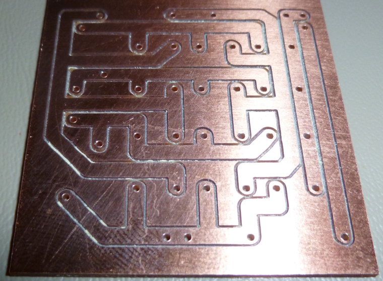
The whole thing fits on a single sided PCB.
-
@dbemowsk said in 6/8 Buttons battery remote node:
@carywin Certain arduinos such as the pro minis can ONLY do interrupts on pins 2 or 3 from my understanding.
IIRC, you can do interrupts from other pins too, but each is tied to a separate bank of pins, so you have to do additional testing to determine which specific pin triggered the interrupt. In the case of the voltage divider keypad, that should be no problem.
-
Here's the link: https://playground.arduino.cc/Main/PinChangeInterrupt
So, in this scenario, it would be:
ISR (PCINT1_vect) pin change interrupt for A0 to A5
-
Here's a revision of the earlier code so that it uses ONLY ONE PIN (namely, A0) on the Arduino. And yes, this does work on a pro mini too, because that's what I tested it on.

//  Description:
//  Use just A0 to process the 12 button keypad.
//  Button press is detected by interrupt set on A0.
//  Which button was pressed is determined by an analog read of A0.

// Note: sleep code borrows from Nick Gammon's Schedule J
// Interrupt code borrows from https://playground.arduino.cc/Main/PinChangeInterrupt

#include <avr/sleep.h>

void pciSetup(byte pin)
{
    *digitalPinToPCMSK(pin) |= bit (digitalPinToPCMSKbit(pin));  // enable pin
    PCIFR  |= bit (digitalPinToPCICRbit(pin)); // clear any outstanding interrupt
    PCICR  |= bit (digitalPinToPCICRbit(pin)); // enable interrupt for the group
}

ISR (PCINT1_vect) // handle pin change interrupt for A0 to A5 here
 {
     //no need to do anything beyond just waking up.
 }

void setup() {
  pinMode(A0,INPUT);
  pciSetup(A0);
  Serial.begin(115200);
  Serial.println("Starting...");
  Serial.flush();
}

void loop() {
  uint16_t voltage;

  set_sleep_mode (SLEEP_MODE_PWR_DOWN);
  sleep_enable();

  // Do not interrupt before we go to sleep, or the
  // ISR will detach interrupts and we won't wake.
  noInterrupts ();

  pciSetup(A0);

  // turn off brown-out enable in software
  // BODS must be set to one and BODSE must be set to zero within four clock cycles
  MCUCR = bit (BODS) | bit (BODSE);
  // The BODS bit is automatically cleared after three clock cycles
  MCUCR = bit (BODS);

  // We are guaranteed that the sleep_cpu call will be done
  // as the processor executes the next instruction after
  // interrupts are turned on.
  interrupts ();  // one cycle
  sleep_cpu ();   // one cycle

  delay(20);  //debounce the button
  voltage=analogRead(A0);  //throw out this first result
  voltage=analogRead(A0);
  if (voltage>700) {
    Serial.println(voltage);
    Serial.flush();
  }
}
-
How does that integrates with mysensors?
-
@gohan That's your department.

-
@neverdie well... kind of... I haven't written mysensors' core so I don't know if it will clash with normal sleep management.
-
Here's an improved sketch that gives you the number (rather than the voltage) of the button that was pressed:
//  Description:
//  Use just A0 to process the 12 button keypad.
//  Button press is detected by interrupt set on A0.
//  Which button was pressed is determined by an analog read of A0.

// Note: sleep code borrows from Nick Gammon's Schedule J
// Interrupt code borrows from https://playground.arduino.cc/Main/PinChangeInterrupt

#include <avr/sleep.h>

int key[12][3] = {  //min and max analogRead values for each key in the 3x4 keypad
                  {0,993,1012},
                  {1,848,865},
                  {2,834,847},
                  {3,800,833},
                  {4,901,914},
                  {5,884,900},
                  {6,866,883},
                  {7,948,969},
                  {8,930,947},
                  {9,915,929},
                  {10,1013,1023},
                  {11,970,992}
                 };

void pciSetup(byte pin)
{
    *digitalPinToPCMSK(pin) |= bit (digitalPinToPCMSKbit(pin));  // enable pin
    PCIFR  |= bit (digitalPinToPCICRbit(pin)); // clear any outstanding interrupt
    PCICR  |= bit (digitalPinToPCICRbit(pin)); // enable interrupt for the group
}

ISR (PCINT1_vect) // handle pin change interrupt for A0 to A5 here
 {
     //no need to do anything beyond just waking up.
 }

 int identifyKey(uint16_t voltage) {
  int i=0;

  while ((i<12) && ((voltage<key[i][1]) || (voltage>key[i][2]))) {
    i++;
  }
  return i;
 }

void setup() {
  pinMode(A0,INPUT);
  pciSetup(A0);
  Serial.begin(115200);
  Serial.println("Starting...");
  Serial.flush();
}

void loop() {
  uint16_t voltage;

  set_sleep_mode (SLEEP_MODE_PWR_DOWN);
  sleep_enable();

  // Do not interrupt before we go to sleep, or the
  // ISR will detach interrupts and we won't wake.
  noInterrupts ();

  pciSetup(A0);

  // turn off brown-out enable in software
  // BODS must be set to one and BODSE must be set to zero within four clock cycles
  MCUCR = bit (BODS) | bit (BODSE);
  // The BODS bit is automatically cleared after three clock cycles
  MCUCR = bit (BODS);

  // We are guaranteed that the sleep_cpu call will be done
  // as the processor executes the next instruction after
  // interrupts are turned on.
  interrupts ();  // one cycle
  sleep_cpu ();   // one cycle

  delay(20);  //debounce the button
  voltage=analogRead(A0);  //throw out this first result
  voltage=analogRead(A0);
  if (voltage>799) {
    Serial.println(identifyKey(voltage));
    Serial.flush();
  }
}
-
@gohan Sorry I don't have a way to measure current that small, but given that it's already run for months on the original batteries, I'm going to assume it's a "normal" Atmega sleep state
-
@dbemowsk The Pro Mini does have pin change interrupts on every pin
-
@neverdie This is correct, but this testing is all handled by the EnableInterrupt library
-
@carywin I stand corrected.
-
@wes said in 6/8 Buttons battery remote node:
I'm planning to use some cheap RF remotes and connect a RF receiver to my RPI, which hosts both my gateway and controller.
I finally received the RF remotes and receiver/decoder from eBay and got them set up to talk directly to my controller - they work pretty well: https://youtu.be/9458-3IiG3Y
I did try a OneButton-type approach on a MySensors node, but had lots of malfunctions with long-presses (e.g. fade up 10% per second whilst the button is depressed), where the the "button pressed" message gets through, but the "button released" message is delayed or dropped.
-
@wes Maybe your resistors don't have a high enough power rating for the current that's running through them? i.e. holding down the button heats them up and therefore changes their resistance? That might explain the slowness to react as expected after the button is released. After release, they cool off and eventually return within their expected resistance tolerance, at which point the expected behavior finally happens.
-
@NeverDie do you think a NRF5x would be better solution to make a small compact remote control?
-
@gohan It's hard to answer a question like that in a vacuum, but in general, I do like nRF5x better than nRF24L01 beause of nRF5x's better link budget. I also like LoRa because of its great range and coverage. I have made remotes using each (and I have made posts about them), and they each have their place.
-
did you post the nrf5x remote in the nrf5x topic or did you made a new one?
-
@gohan It was on the nRF5 action! thread and for LoRa it was on the CNC thread.