@skywatch Take a look at my pan tilt project. A stepper i.s.o. servo can easily be achieved. I would recommend to use the AccelStepper lib to have a smooth movement.
Posts made by AWI
-
RE: Pan Tilt stepper motors
-
RE: ๐ฌ Micro (nano) ampere meter (double)
@mfalkvidd the 'local adc' library is the hx711 library which I placed in the sketch folder. Sorry for the confusion
-
RE: Double Micro (nano) Ampere meter
@NeverDie @Nca78 a lot going on here Nice to see that my afternoon project sparked creativity.
I started this to be a datalogger for remote monitoring of MySensors node power consumption. During the run changed my mind and it turned out to be this which fits my needs. But all options are still open..
The converter has a max sample rate of 80Hz which was default on the board I used. I balanced accuracy and readability by applying sample averaging. This averages out much of the noise from USB source etc.
The sparkfun boards are probably designed a little different and don't have the shield which helps to keep out noise.
To increase speed you can change the amount of averaging (number of readings per sample)
To get a better response for the button the way is to go for non blocking (averaging) readings of the Adc. The library is very basic so that would be the best place to start. -
RE: nRf24L01+ connection quality meter
@dakipro It would take a resistor and analog power reading to include basic power measurement. Current would vary between ~3mA and 70mA (with amplified radio).
-
RE: Your workshop :)
@gohan I used a kit. There is also a description and suggestions on improvement of the "Chinese clones" in the documentation of the project.
-
RE: Your workshop :)
@Yveaux I soldered the thing myself so build quality is .... The board I received looks to be solid as well as the components.
Accuracy in resistor/ capacitor meaurement is fine (~5% which is also the toleration of the components tested) Semiconductor analysis is enough for me with Fet / Junction transistors as I can determine the most important characteristics (including the pin layout!) which are within 10% of the datasheet. (pins are 100% correct :-)) -
RE: Your workshop :)
@gohan said in Your workshop :
Aren't these devices basically Arduinos? It's written on the title atmega328. If so if we could get our hands on the code, we could make our own
I finally found the place where the Chinese get their code and design for the "Transistortester". It comes from a german site
a very extensive project. I doubt if I will ever be able to match or even comprehend what they accomplished. -
RE: DC meter for PV ouput measuring and data logging
@tailchopper I wonder if you wouldn't be better of on another forum. MySensors provides an infrastructure for home-automation and IoT. If you are not into connecting it to a MySensors ecosystem there are some dedicated PV (power monitoring) forums which probably give you more focussed / better answers. Like Openenergymonitor
-
RE: DC meter for PV ouput measuring and data logging
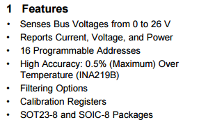
@tailchopper It would depend on the output voltage & current of your PV panel. Up to 26V 3.2A the ina219 is a very convenient all-in-one sensor with I2C interface.
-
RE: Double Micro (nano) Ampere meter
@NeverDie said in Double Micro (nano) Ampere meter:
It looks a bit complicated to me
btw. Which part looks complicated? It's just a few resistors attached to an ADC board (and sketch ready) I am curious on how you can build something simpler with the ADS1220 (which seems to be a better ADC if you are able to find it somewhere ;-))
-
RE: Your workshop :)
@Jan-Gatzke For MySensor I use it mostly for measuring response times and get a general idea of what is happening timewise. Especially if you have multiple event happening at the same time. Also for getting a grip on low power
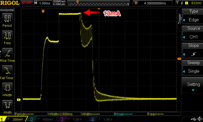
it gives a lot of information which would be very hard to measure with any other instrument. (for my other hobby, analog audio design, I couldn't live without it. ;-))
A few considerations:
- It can be rather complicated using a scope in first instance. (a steep learning curve)
- Unless you are just curious and want to educate yourself I would strongly disencourage buying a cheap instrument. Better to study a few manuals of serious > โฌ300 instruments, save a little and buy the thing you need (or can't resist). 10 years ago you had to put down > โฌ1000 for something reasonable.
-
RE: Pump + Relais + Decoupling
@Naitsirhc Since you are using the amplified Radio (PA/LNA) with the socket adapter board he decoupling for the radio should be fine. There are a few discussions on the forum on what kind of problems you can encounter.
First suggestion I have is lowering the transmission energy#define RF24_PA_LEVEL RF24_PA_LOW
and make sure you have a sufficient supply (not the on-board ldo of the nano or an FTDI adapter). -
RE: Your workshop :)
@gohan Be aware that there are quite a few different versions around. The one I posted has a rotary encoder to select and operate the pwm and frequency functions. The perspex casing fits well with the rest of the nerdy testboxes I own (dummy load, power supply, a few function generators, frequencycounter ) All a lot of functionality for very little..
-
RE: Double Micro (nano) Ampere meter
@NeverDie that one would work as well. Maybe harder to get and a little more pricy
-
RE: Has anyone made their own lab power supply out of a PSU?
@pansen Then you would miss the fun and flexibility . A good combination of cheap available stuff in combination with (adjustable) linear components is giving me everything I need.
- The ATX fixed voltages (heavily "denoised") for most MySensors and LED stuff (3.3, 5, 12, > 5 Amps)
- An adjustable (and programmable) linear supply (fed by the ATX) like ยตSupply.
-
RE: ๐ฌ Micro (nano) ampere meter (double)
@Nca78 Looks good, Hard to say why the response is slow. There is quite some averaging in taking readings from the ADC and I tried to find a right balance between accuracy and response time/ button behaviour. For me it is not spot on but very usable.
You could try to remove some of the averaging to get a better refresh rate. (i.e. the "32" to "8") -
RE: Any parallel interface accellerometers ?
@ny51sens I'm curious what kind of application you are looking at. You can take a look at ADXL377 (analog sensor) and use whatever kind of ADC to read parallel at enormous speeds..
-
RE: PIR am312
@hek @NeverDie @kontrollable My stupid mistake... I was referring to this from the datasheet Pir-AS312
-
RE: Any parallel interface accellerometers ?
@ny51sens The "standard" alternative would be the SPI (serial) interface. A parallel interface imho would be not very efficient considering the size of the information and relatively low sampling rates of the sensors.
-
RE: PIR am312
@NeverDie The "specification" is a link back into this forum (https://forum.mysensors.org/topic/6658/pir-sensors/18) so you should be able to access it...
-
RE: PIR am312
@sundberg84 I turned the voltage down to 2.6V and it was still fully functional. Did not test noise sensitivity (disassembled the test set-up) The sensor is specified to 2.7V, the LDO (HT-7530) has a typical voltage drop of 100mV in normal operation.
Seems to be very small (< 5mV) when Vin is below 3V.
Conclusion: looks good for 2AA alkaline. -
RE: PIR am312
@NeverDie It looks like its in specification. My "lab" is not that big... I could easily detect around 5 meters through the open door
-
RE: Has anyone made their own lab power supply out of a PSU?
What about this "pico ATX" board. Standard connector, can be powered from a standard 12 supply and deliver 150W... (= a lot of MySensor nodes ;-))
-
RE: PIR am312
I just received my samples of the AM312 and ( @gohan as promised) my observations/ measurements. (which are not in line with @acp observations above)
- Rock stable. Even if I use the on-board regulator to also power a MySensors node it does not get into trouble (fires only when supposed to)
- The hold-time is as specified in the datasheet 2.3 seconds
- Power consumption: 14.2 ยตA! when idle 15.4 ยตA when active.
- These boards can handle anywhere between 3.3 and 12 V power (ldo on-board).
- I won't be using any of the small or modified HC-SR501 or similar BISS0001 based sensors anymore. These typically have 4 times higher power consumption/ very sensitive to all kinds of power and environment noise/ large/ but adjustable (can live with that and handle in software).
-
RE: Help with Using Multiple NRF24+ Radio + Sensors and One Gateway
@moonlight0551 The NODE_ID will have to be unique for a sensor node. Domoticz will generate a unique ID if you do not specify it yourself. The API gives you the details.
-
RE: RGB LED strip
@maghac The FastLed library has some functions for linear fading. The characteristics of the Mosfet's can be ignored. When using PWM these are used as switches (i.e. on/off).
For inspiration: this sketch was for a RGBW strip and uses the FastLEDnscale8()
for smooth fading. Also there is a non-blocking version of the fading routine and a state machine to have button control.
(the 'W' in the RGBW can easily be removed. It is calculated here as a kind of greatest common divisor of RGB)/* PROJECT: MySensors / RGB light NEOPIXEL PROGRAMMER: AWI DATE: october 10, 2015/ last update: september 20, 2016 FILE: AWI_Wall_LIght_x.ino LICENSE: Public domain Hardware: RGBW Pro Mini and MySensors 2.0, Special: uses Fastled library (great & fast RBG/HSV universal library) https://github.com/FastLED/FastLED SUMMARY: Different patterns and brightness settings Button switches on/off and color with long press Remarks: Fixed node-id Change log: 20160915 - Updated to MySensors 2.0 20160920 - Changed state change to dimmer i.s.o. switch() 20161120 - Various small adjustments 20170120 - Change to RGBW non addressable strip */ //**** MySensors ***** // Enable debug prints to serial monitor #define MY_DEBUG #define MY_RADIO_NRF24 // Enable and select radio type attached #define MY_NODE_ID 63 // 62 #define NODE_TXT "W 63" // Text to add to sensor name // change the pins to free up the pwm pin for led control #define MY_RF24_CE_PIN 4 //<-- NOTE!!! changed, the default is 9 #define MY_RF24_CS_PIN 10 // default is 10 //#define RF24_PA_LEVEL RF24_PA_MAX // helpers #define LOCAL_DEBUG // enable if print wanted #ifdef LOCAL_DEBUG #define Sprint(...) (Serial.print( __VA_ARGS__)) // macro as substitute for print, enable if no print wanted #define Sprintln(...) (Serial.println( __VA_ARGS__)) // macro as substitute for println #else #define Sprint(a) #define Sprintln(a) #endif #include <SPI.h> // My Sensors #include <MySensors.h> #include <FastLED.h> // https://github.com/FastLED/FastLED #include "Button.h" // https://github.com/JChristensen/Button // Arduino pin attached to drivers const int RED_PIN = 5 ; const int WHITE_PIN = 9 ; const int GREEN_PIN = 3 ; const int BLUE_PIN = 6 ; const int buttonPin = 7 ; // push button const int RGB_LightChild = 0 ; // Child Id's, standard light child on/off/ dim const int RGB_RGBChild = 1 ; // RGB light child (on/off/dim/color, if controller supports V_RBG)) CRGB strip ; // RGB(W) strip (Fastled) uint8_t stripW = 0 ; // White component uint8_t actualBrightness = 0xFF ; // actual strip brightness // Kelving colors: Light & daylight (in Fastled reference only) /// 1900 Kelvin Candle=0xFF9329 /* 1900 K, 255, 147, 41 */, /// 2600 Kelvin Tungsten40W=0xFFC58F /* 2600 K, 255, 197, 143 */, /// 2850 Kelvin Tungsten100W=0xFFD6AA /* 2850 K, 255, 214, 170 */, /// 3200 Kelvin Halogen=0xFFF1E0 /* 3200 K, 255, 241, 224 */, /// 5200 Kelvin CarbonArc=0xFFFAF4 /* 5200 K, 255, 250, 244 */, /// 5400 Kelvin HighNoonSun=0xFFFFFB /* 5400 K, 255, 255, 251 */, /// 6000 Kelvin DirectSunlight=0xFFFFFF /* 6000 K, 255, 255, 255 */, /// 7000 Kelvin OvercastSky=0xC9E2FF /* 7000 K, 201, 226, 255 */, /// 20000 Kelvin ClearBlueSky=0x409CFF /* 20000 K, 64, 156, 255 */ char setRGBvalue[] = "FEBC5400"; CRGB curRGB = 0xFEBC54 ; // Controller sent RGB(W) value, default tungsten40W "FFC58F" uint16_t curBrightness = 0xFF, setBrightness = 0xFF ; // Brightness globals (actualBrightness) unsigned long updateBrightnessDelay, lastBrightnessUpdate ; // Brightness timers int RGBonoff ; // OnOff flag unsigned long idleTimer = millis() ; // return to idle timer const unsigned long idleTime = 10000UL; // return to idle after 10 secs const unsigned long dimTime = 1000UL; // dim period const unsigned long heartbeatInterval = 1 * 60UL * 1000UL ; // heartbeatinterval, just to let the controller know I am alive unsigned long heartbeatCounter = 0 ; MyMessage lightRGBMsg(RGB_LightChild, V_RGB); // standard messages, light MyMessage lightdimmerMsG(RGB_LightChild ,V_DIMMER); MyMessage lightOnOffMessage(RGB_LightChild, V_STATUS); Button myBtn(buttonPin, true, true, 20); //Declare the button (pin, pull_up, invert, debounce_ms) // Simple state machine for button state enum {sIdle, sBrightness, sPattern} ; // simple state machine for button press int State ; void setup() { pinMode(RED_PIN, OUTPUT); pinMode(GREEN_PIN, OUTPUT); pinMode(BLUE_PIN, OUTPUT); pinMode(WHITE_PIN, OUTPUT); request(RGB_LightChild, V_RGBW) ; /*for(int i = 0 ; i < 6 ; i++) { // get color value from EEPROM (8 char for RGBW) setRGBvalue[i] = loadState(i) ; } curRGB = strtol( setRGBvalue, NULL, 16); // copy the RGB value to the led Strip (convert to long) showAnalogRGB() ; */ } void presentation(){ // MySensors sendSketchInfo("AWI RGBW strip " NODE_TXT, "2.0"); wait(50) ; present(RGB_RGBChild, S_RGB_LIGHT, "RGB RGBW strip " NODE_TXT); wait(50) ; } // read button and act accordingly // short press: on/off // longer press: set patterns with following short press // long press: set brightness increase void loop() { myBtn.read(); //Read the button (only read) unsigned long now = millis(); // loop timer reference switch (State) { case sIdle: // default state, browse through patterns if (myBtn.wasReleased()){ // light on/ off in idle RGBonoff = !RGBonoff ; // invert light state setLightBrightness((RGBonoff == 1)?setBrightness:0, dimTime); send(lightOnOffMessage.set(RGBonoff)); // and update controller } else if (myBtn.pressedFor(800)){ // move to Pattern update state with long press idleTimer = now ; // return to idle after ... State = sPattern ; } break ; case sPattern: // entered after long press/ change colors (tbd) if (myBtn.pressedFor(4000)){ // when press even longer move to Brightness update State = sBrightness ; } else if (myBtn.wasPressed()){ //setPattern = (setPattern + 1) % lastPatternIdx ; // increase pattern and wrap //setLightPattern((setPattern), 500 ); idleTimer = now ; } else if ( now > idleTime + idleTimer ){ // return to idle after ... State = sIdle ; } break ; case sBrightness: // entered after looong press if (myBtn.wasPressed()){ // if pressed again increase brightness setLightBrightness((curBrightness+0x1F) % 0xFF, 0) ; // increase brightness and wrap (0..0xFF) idleTimer = now ; } else if ( now > idleTime + idleTimer ){ // return to idle after ... State = sIdle ; } break ; default : State = sIdle ; break ; } updateLightBrightness(); // update Brightness if time if ( now > heartbeatCounter + heartbeatInterval){ // heartbeat every hour sendHeartbeat(); heartbeatCounter = now ; } } // Sets the light brightness, takes value and time (ms) as input void setLightBrightness(int newBrightness, unsigned long updateTime){ // global: curBrightness, actualBrightness, updateBrightnessDelay updateBrightnessDelay = updateTime / 0xFF ; // delay = time / max steps curBrightness = newBrightness ; // set curBrightness to new value, rest is done in update } // Update the light brightness if time void updateLightBrightness(){ // global: curBrightness, actualBrightness, updateBrightnessDelay, lastBrightnessUpdate ; //static byte actualBrightness ; // store real brightness state for slow dim unsigned long now = millis() ; if (now > lastBrightnessUpdate + updateBrightnessDelay){// check if time for update if ( actualBrightness > curBrightness) { --actualBrightness ; showAnalogRGB() ; } else if ( actualBrightness < curBrightness){ ++actualBrightness ; showAnalogRGB() ; } lastBrightnessUpdate = now ; } } // Incoming messages from MySensors void receive(const MyMessage &message){ int ID = message.sensor; Serial.print("Sensor: "); Serial.println(ID); switch (ID){ case RGB_LightChild: // same behaviour as RGB child/ fall through case RGB_RGBChild: // if controller can handle V_RGB if (message.type == V_RGB) { // check for RGB type strcpy(setRGBvalue, message.getString()); // get the payload curRGB = strtoul( setRGBvalue, NULL, 16) ; // copy the RGB value to the led Strip (convert to long) } else if (message.type == V_RGBW) { // check for RGB type strcpy(setRGBvalue, message.getString()); // get the payload curRGB = strtoul( setRGBvalue, NULL, 16) >> 8; // copy the RGB value to the led Strip (convert to long) } else if (message.type == V_DIMMER) { // if DIMMER type, adjust brightness setBrightness = map(message.getInt(), 0, 100, 0, 255); setLightBrightness(setBrightness, dimTime) ; } else if (message.type == V_STATUS) { // if on/off type, toggle brightness RGBonoff = message.getInt(); setLightBrightness((RGBonoff == 1)?setBrightness:0, dimTime); } break ; } showAnalogRGB(); dispRGBstat(); } // showAnalogRGB: this is like FastLED.show(), but outputs on // analog PWM output pins instead of sending data to an intelligent, // pixel-addressable LED strip. void showAnalogRGB(){ strip = curRGB ; strip.nscale8(actualBrightness) ; int commonRGB = min(min(strip.r, strip.g), strip.b) ; // smallest value is White component strip.r -= commonRGB ; strip.g -= commonRGB ; strip.b -= commonRGB ; stripW = commonRGB ; Sprint("Color RGBW ") ; Sprint(strip.r, HEX); Sprint(" ") ; Sprint(strip.g, HEX); Sprint(" ") ; Sprint(strip.b, HEX); Sprint(" ") ; Sprintln(stripW, HEX) ; analogWrite(RED_PIN, strip.r ); analogWrite(GREEN_PIN, strip.g ); analogWrite(BLUE_PIN, strip.b ); analogWrite(WHITE_PIN, stripW ) ; } // debug // display the status of all RGB: controller, requested, real void dispRGBstat(void){ Serial.print(" Color: "); Serial.print(setRGBvalue); Serial.print(" Brightness: "); Serial.println(setBrightness); } ```
-
RE: RGB LED strip
@maghac You can setup Notepad++ to run the arduino IDE
There is a good instruction (in German ;-), use google translate if you need to ) here
-
RE: best approach to add MySensors Node to an existing smoke detector?
@dirkc The buzzer is most likely only powered when an alarm sounds Leakage in the optocoupler "transistor" is mostly in the nano ampere (nA) region when off. So I would suggest you measure the voltage over the buzzer when sounding (protect your ears!). Add a series resistor (estimate 300 ohm to 1k) with the optocoupler LED.
On the MySensor node side 700k to 1M as collector pull-up to the optocoupler and attach to INT0 or 1 and treat like a Motion node. Power the node with a capable LDO (mcp1700 or similar, watch the input voltage (9v)). -
RE: Your workshop :)
@Yveaux An updated version ... this one generates PWM, measure frequency and even measures DS18B20 / DHT..
-
RE: Slim Node as a Mini 2AA Battery PIR Motion Sensor
@Komaandy how are you powering the circuit?
The pir sensor is very sensitive to power fluctuations and not suited for below 3v. Also for 3v you need to "modify" the sensors power circuit. You should be able to find a lot of information when searching for the sensor. -
RE: ๐ฌ Micro (nano) ampere meter (double)
@Koresh The offset is accomplished with a 2 * 1k voltage divider between Aref and gnd.
It is probably a good idea to list all our (undocumented) projects to share with the MySensors community -
RE: Double Micro (nano) Ampere meter
@gohan No special tolerance resistors needed. The only reason for choosing metal film resistors is that their temperature coefficient is better than carbon types (typical 50ppm/ยฐC compared to 200-500ppm/ยฐC).
As you will be calibrating the circuit you can choose from a large range (0.1 Ohm - 100 Ohm) for the shunt. This will only influence the burden voltage / sensitivity and range (Ohm's laws). -
RE: High current
@pansen What i meant is that the MySensors API only specifies the (hw) INT0/INT1 RISING/ FALLING/ CHANGE. All of these work as expected.
-
RE: Double Micro (nano) Ampere meter
@gohan As mentioned in the description: I use it as a "patch panel" to distribute the power and ground to different devices. Wiring tends to get messy on my workbench...
Not mine but similar -
RE: Double Micro (nano) Ampere meter
There it is Micro (nano) ampere meter (double). I need to add a schematic drawing. Any suggestions/ questions are welcome.
-
RE: Double Micro (nano) Ampere meter
@DavidZH Impressive only by numbers I am prepared to trade my ยตCurrent for the Agilent
A meetup sounds good..any specific plans yet? -
RE: High current
@pansen The pinchange interrupt is a different feature in the atmega. It can be used on any pin and is not supported in MySensors. That is why you need to make sure yourself that everything goes to sleep as wanted.
-
RE: Scrolling Text sensor node with new V_TEXT
@shabba Try without using "String" type use "char[x]" instead. In general you should try to avoid using this type in real time environments.
send(msg2.set("Blah"));
should do the trick in first instance. -
Double Micro (nano) Ampere meter
A very low current (double) stand alone uA meter to tune MySensors battery nodes..
I de' MySensor'ized this project because it is more usefull on the workbench for measuring the very low currents of MySensors battery nodes. I own several Ampere meters including the famous ยตCurrent. Many of these are not accurate enough or need a lot of wiring and additional equipment (ยตCurrent). I just wanted something simple and stand alone
Using the low cost HX711 weight scale 24 bit AD converter a sub 10โฌ cost double ยตA meter was born. Some characteristics to fit MySensors projects:- range channel A: ยฑ 20mA 5ยฝ-6ยฝ digit ยตA
- range channel B: ยฑ40mA 5ยฝ-6ยฝ digit ยตA
- burden voltage 1ยตV/1ยตA (internal resistance 1โฆ)
- 'patch panel' on the connectors.
- easy calibration.
In comparison with the ยตCurrent and a standard multimeter in uA range
The internals:
Although it cannot compare in accuracy with the ยตCurrent (in combination with a good multimeter) it is more than useable and accurate to do some serious MySensors tuning.
If there is some interest I will try to publish a decent built instruction on Openhardware.io.
-
RE: Status Display Based on WS2812b LEDS
@kallii Sure, all you need is in the MySensors and FastLed libraries..
-
RE: ๐ฌ Ikea Molgan Hack
@LastSamurai As long as you can be sure the Vcc of the Arduino stays around 3.3v you can use a 3.3v zener. If you power as indicated (2 AA cells) voltage can drop below 2V and that cannot be considered safe. As an alternative to the zener you can have a resistor voltage divider (or stack a few normal diodes).
-
RE: Status Display Based on WS2812b LEDS
@kallii MySensors won't be the issue here. Try some of the examples of the FastLED library and you will be amazed.
I can help you to get started if you have the basics.. -
RE: Can a Node Send json?
@dpcr You cannot ignore the character limit in MySensors by using a different V_ type. You either have to split the information in pieces that can be handled or have the controller do the handling for you.
Also Domoticz uses the S_CUSTOM type in a very specific way.scripting in Domoticz is easy in Lua. What I would suggest is to build your tag 'database' in Domoticz (eg. a sensor for each tag) and handle logging from LUA.
-
RE: Molgan and Emengency Light
@markcame
#define MY_NODE_ID xxx
in the start of your sketch -
RE: Capacitors and switching power supplies
@ronnyandre Things are sooo easy (if you have a degree in electronics ) An effective design includes multiple filters and depends for a great deal on the switching frequency (and harmonics). A typical design could look like this.
An linear regulator (like LM7805) can be very effective for low frequencies (~ < 10kHz) but not for high frequencies.
In most of the cases when working with phone mains adapters the 'standard' (uno/ nano) regulator (1117) with capacitors damps sufficiently.
-
RE: Molgan and Emengency Light
@markcame apart from that there is some variable type mixing (bool, int, ) the sketch looks fine. Domoticz returns values for: V_STATUS, V_PERCENTAGE, V_RGB(W), V_VARx and V_TEXT (see code snippet below (github))
You can try to have the sensor re-create in Domoticz with a fixed node Id. Experimenting could have caused Domoticz to mess up the database.if (message_type == MT_Req) { //Request a variable std::string tmpstr; switch (sub_type) { case V_STATUS: case V_PERCENTAGE: case V_RGB: case V_RGBW: if (GetSwitchValue(node_id, child_sensor_id, sub_type, tmpstr)) SendNodeCommand(node_id, child_sensor_id, message_type, sub_type, tmpstr); break; case V_VAR1: case V_VAR2: case V_VAR3: case V_VAR4: case V_VAR5: //send back a previous stored custom variable tmpstr = ""; GetVar(node_id, child_sensor_id, sub_type, tmpstr); //SendNodeSetCommand(node_id, child_sensor_id, message_type, (_eSetType)sub_type, tmpstr, true, 1000); SendNodeCommand(node_id, child_sensor_id, message_type, sub_type, tmpstr); break; case V_TEXT: { //Get Text sensor value from the database bool bExits = false; tmpstr = GetTextSensorText(node_id, child_sensor_id, bExits); SendNodeCommand(node_id, child_sensor_id, message_type, sub_type, tmpstr); } break; default: while (1==0); break; } while (1==0); }
-
RE: Molgan and Emengency Light
@markcame can you please post your sketch showing the request?
-
Molgan-Hack hack
A variant on @Yveaux 's Molgan-Hack board design.. A 'spaghetti' project to add a few nice to have features:
- Switch light on if movement (only if dark)
- Slow brightness increase/ decrease
- and .. not really much more
- blue: LDR light measurement)
- red: ldo with voltage divider.
- rest: a bunch of wires. of which one is controlling the Molgan's original leds.
As there are only a few pins broken out I soldered most on the Avr smd. I consider it an exercise ... with good result.
Molgan Slow dim โ 00:08
โ Ad Imhoff -
RE: Rebuild of my broken 433mhz Cresta/hideki UV-Sensor
@sundberg84 The internal reference is around 1.1V. A reading of 1024 will therefore be 1.1V like @core_c mentioned in a previous posting. All analog inputs will use this reference (if not changed in the mean time ;-)) But if you have a stable LDO powering the Arduino there is nothing wrong with using the external (Vcc) reference. It's main use is avoiding external components when powering directly from batteries. (ref @Yveaux 's Vcc lib).
-
RE: Molgan and Emengency Light
@markcame I'm doing a similar thing with @Yveaux 's Molgan-Hack board. Interesting to see that you are using the
wait()
function in the extended versionresponse=wait(5000, 2, V_TEXT);
I never noticed that it existed
A few remarks:- Domoticz can handle requests for (light)
V_STATUS
which fits the purpose better (and is more efficient) - Using the extend version of wait the second parameter
cmd
should be the MySensors command typeset
(value = = 1) as the node will be receiving aset
from the controller. You better use the constant nameC_SET
although not mentioned in the API (yet). InMyMessage.h
:
/// @brief The command field (message-type) defines the overall properties of a message typedef enum { C_PRESENTATION = 0, //!< Sent by a node when they present attached sensors. This is usually done in presentation() at startup. C_SET = 1, //!< This message is sent from or to a sensor when a sensor value should be updated. C_REQ = 2, //!< Requests a variable value (usually from an actuator destined for controller). C_INTERNAL = 3, //!< Internal MySensors messages (also include common messages provided/generated by the library). C_STREAM = 4 //!< For firmware and other larger chunks of data that need to be divided into pieces. } mysensor_command;
- Domoticz can handle requests for (light)
-
RE: Byte clock [8] error
@Victor You can't expect the community to run and find possible causes of problems with posting only a reference to a sketch. Please use the guideline on how to ask for help.
-
RE: Where does MySensor store in EEPROM
@goranrad The
Write_Check
constant is meant to check if there is a valid number written in EEPROM. As the sketch writes from EEPROM adress "0x00" there is good chance that it interferes with MySensors as it uses the same start point
#define EEPROM_START (0u)
(defined in MyEepromAddresses.h)I would advice to rewrite the code to use the MySensors
saveState(..)
andloadState(..)
-
RE: Byte clock [8] error
@Victor Please provide more information like the whole error message and sketch.
-
RE: fody weather station, wind sensor
@flopp the Ir 'emitter' is probably a led so you need a current of a few milli amps. Start low (1 kOhm in series) and find out when it starts to function.
-
RE: <SOLVED>Domoticz adds constantly new devices when using manual DeviceAddress for DS18B20
@edsteve It's no beauty... I have not compiled it so possibly a few syntax errors (and I may have switched some temperature numbers ;)). I like to be awarded with gratitude being a servant to this community... get yourself in the Hall of fame by making a donation to MySensors
#define MY_RADIO_NRF24 #define MY_DEBUG #include <MySensors.h> #include <SPI.h> #include <OneWire.h> #include <DallasTemperature.h> // Data wire is plugged into port 2 on the Arduino #define ONE_WIRE_BUS 4 #define TEMPERATURE_PRECISION 10 // Setup a oneWire instance to communicate with any OneWire devices (not just Maxim/Dallas temperature ICs) OneWire oneWire(ONE_WIRE_BUS); // Pass our oneWire reference to Dallas Temperature. DallasTemperature sensors(&oneWire); #define NODE_ID 1 #define CHILD_ID_WIND 1 #define CHILD_ID_TEMP1 3 #define CHILD_ID_TEMP2 4 #define CHILD_ID_TEMP3 5 #define CHILD_ID_TEMP4 6 #define CHILD_ID_TEMP5 7 unsigned int val_wspeed; unsigned int val_wgust; unsigned int val_wdirection; unsigned int last_wspeed; unsigned int last_wgust; unsigned int last_wdirection; DeviceAddress temp1 = { 0x28, 0xEE, 0xB6, 0xB1, 0x27, 0x16, 0x01, 0x1F }; DeviceAddress temp2 = { 0x28, 0xEE, 0xE1, 0x20, 0x28, 0x16, 0x01, 0xEA }; DeviceAddress temp3 = { 0x28, 0xEE, 0x0D, 0xAA, 0x24, 0x16, 0x02, 0x8A }; DeviceAddress temp4 = { 0x28, 0xEE, 0x7D, 0xA8, 0x24, 0x16, 0x02, 0xE0 }; DeviceAddress temp5 = { 0x28, 0xFF, 0xF6, 0x8F, 0x62, 0x16, 0x03, 0x7F }; MyMessage msgWSpeed(CHILD_ID_WIND, V_WIND); MyMessage msgWGust(CHILD_ID_WIND, V_GUST); MyMessage msgWDirection(CHILD_ID_WIND, V_DIRECTION); MyMessage msg(0,V_TEMP); void setup(void) { // start serial port Serial.begin(115200); Serial.println("Dallas Temperature IC Control Library Demo"); // Start up the library sensors.begin(); // report parasite power requirements Serial.print("Parasite power is: "); if (sensors.isParasitePowerMode()) Serial.println("ON"); else Serial.println("OFF"); // set the resolution to 9 bit sensors.setResolution(temp1, TEMPERATURE_PRECISION); sensors.setResolution(temp2, TEMPERATURE_PRECISION); sensors.setResolution(temp3, TEMPERATURE_PRECISION); sensors.setResolution(temp4, TEMPERATURE_PRECISION); sensors.setResolution(temp5, TEMPERATURE_PRECISION); } void presentation() { present(CHILD_ID_WIND, S_WIND); present(CHILD_ID_TEMP1, S_TEMP); present(CHILD_ID_TEMP2, S_TEMP); present(CHILD_ID_TEMP3, S_TEMP); present(CHILD_ID_TEMP4, S_TEMP); present(CHILD_ID_TEMP5, S_TEMP); } void loop() { // call sensors.requestTemperatures() to issue a global temperature // request to all devices on the bus Serial.print("Requesting temperatures..."); sensors.requestTemperatures(); Serial.println("DONE"); // print the device information float east = sensors.getTempC(temp1); Serial.print("East C: "); Serial.println(east); send(msg.setSensor(CHILD_ID_TEMP1).set(east,1)); float north = sensors.getTempC(temp2); Serial.print("North C: "); Serial.println(north); send(msg.setSensor(CHILD_ID_TEMP2).set(north,1)); float west = sensors.getTempC(temp5); Serial.print("West C: "); Serial.println(west); send(msg.setSensor(CHILD_ID_TEMP5).set(west,1)); float south = sensors.getTempC(temp3); Serial.print("South C: "); Serial.println(south); send(msg.setSensor(CHILD_ID_TEMP3).set(south,1)); float temp33 = sensors.getTempC(temp4); Serial.print("Test C: "); Serial.println(temp33); send(msg.setSensor(CHILD_ID_TEMP4).set(temp4,1)); // calculating wind direction form temperature differences if (north > south && north > west && north > east ) { Serial.println("SOUTH"); unsigned int val_wdirection = 180; send(msgWDirection.set(val_wdirection)); Serial.print("WD: "); Serial.println(val_wdirection); } if (east > north && east > west && east > south ) { Serial.println("WEST"); unsigned int val_wdirection = 280; send(msgWDirection.set(val_wdirection)); Serial.print("WD: "); Serial.println(val_wdirection); } if (south > north && south > west && south > east ) { Serial.println("NORTH"); unsigned int val_wdirection = 0; send(msgWDirection.set(val_wdirection)); Serial.print("WD: "); Serial.println(val_wdirection); } if (west > north && west > south && west > east ) { Serial.println("EAST"); unsigned int val_wdirection = 90; send(msgWDirection.set(val_wdirection)); Serial.print("WD: "); Serial.println(val_wdirection); } //domoticz must see speed and gust so i give random numbers for testing unsigned int val_wspeed = 17; if(last_wspeed != val_wspeed) { last_wspeed = val_wspeed; send(msgWSpeed.set(val_wspeed, 1)); Serial.print("WS: "); Serial.println(val_wspeed); } unsigned int val_wgust = 5; if(last_wgust != val_wgust) { last_wgust = val_wgust; send(msgWGust.set(val_wgust, 1)); Serial.print("WG: "); Serial.println(val_wgust); } sleep (5000); }
-
RE: <SOLVED>Domoticz adds constantly new devices when using manual DeviceAddress for DS18B20
@edsteve said in Domoticz adds constantly new devices when using manual DeviceAddress for DS18B20:
DeviceAddress temp1 = { 0x28, 0xEE, 0xB6, 0xB1, 0x27, 0x16, 0x01, 0x1F };
You are using a type
DeviceAdress
type to indicate a sensor id.
ie.send(msg.setSensor(temp1).set(east,1));
The sensor number should be of a simple
int
(oruint8_t
) type. I suggest to useCHILD_ID_TEMP + tempNo
where tempNo is the number of the temp sensor.. -
RE: Watermark arduino 3.3 headache
@ecabanas Your sketch and circuit look fine to me. I don't know the Sodaq One, but should the line
const int LeafSensor1=0; //Leaf Sensor on Analog Pin 0
not refer to pin "A0"...
const int LeafSensor1=A0; //Leaf Sensor on Analog Pin 0
? -
RE: Watermark arduino 3.3 headache
@ecabanas Reading from what is published on the watermark sensors it is "resistance" based. E.g. a couple of electrodes in a nice housing and corrosion resistant. Standard method of reading these sensors is determine resistance (Ohms law) by applying a (AC = reversing polarity) current and measuring the voltage over the sensor. Most of the moisture sketches are written this way. You need to know the "resistance / moisture curve" of the sensor.
Can you show us what have and tried?
-
RE: Can't get MySensors to work - someone got an easy sketch?
@maxdorable Welcome on the forum. The first steps are the steepest it seems like the node cannot find its parent. In many cases this is related to radio problems. Have you tried the steps in the "Troubleshooting" section?
-
RE: Things get funky when there's a bit more traffic
@mtiutiu Just curious, what are you using now for the gateway?
-
RE: RGB LED strip controller with FastLED
@pansen To add to that... these step down Power converter(boards) are not really suited for low power applications. Their efficiency is likely (much) worse than a linear regulator.
-
RE: RGB LED strip controller with FastLED
@pansen Agree and price is one thing but I would prefer a linear regulator for its stability and noise.
-
RE: False positives for HC-SR501 PIR battery node
@Vladimir-Dobrikov a step-up can be a cause of noise. I try to avoid these if possible. Three AA batteries or a lithium ion cell would be my choice.
-
RE: False positives for HC-SR501 PIR battery node
@Vladimir-Dobrikov If you power the whole thing from batteries (2 AA, 3V) then for sure it is power related. The PIR is very sensitive to power fluctuations and unstable below 3v.
You can try a large capacitor on the power lines but I doubt it... -
RE: Extra command message type for local data requests
@BartE I had (and maybe have) a similar need. Domoticz does something like that with S_CUSTOM which can request all kinds of data from the the controller. I have 'solved' it by duplicating the data with a controller script to a sensor specific 'dummy sensor' so that it can be retrieved with a request from the controller.
Problem with having a controller dependent number would be 'controller dependency' so I'm not sure...
(and a better name would be 'controllerRequest' ) -
RE: [SOLVED] Sleep dont run
@mar.conte The hcr501 will become unstable below 3V. So if you are powering it with 2AA you can expect problems.
-
RE: Sleep() with interrupt only works with level "LOW"
@ileneken3 Could it be that your sensor is better handled with a RISING or FALLING interrupt? CHANGE fires on both edges. Else post your whole sketch and debug log.
-
RE: LEACH Protocol
@SebastianB Software only but like @Anticimex mentioned LEACH would replace the MySensors networking. However you could use the serial protocol or MQTT for message encoding
-
RE: LEACH Protocol
@SebastianB For what I know of LEACH its abstraction kind of replaces the MySensors layer. MySensors handles the network topology (routing, repeating, forwarding) . I guess you can learn a lot from how MySensors handles the different radio protocols (rfm24 etc.) but choose to build on the radio interface of rfm24/69
-
RE: Sleep() with interrupt only works with level "LOW"
@Yveaux Good find! and good news
-
RE: Sleep() with interrupt only works with level "LOW"
@Yveaux Not really.. since 2.1.1 I'm losing it... Still in the process of finding differences with the previous version...
-
RE: Sleep() with interrupt only works with level "LOW"
@Yveaux Pigheaded as I am... (AVR made some more mistakes in their documentation) .. I got 12 different atmega328p processors from different sources on the test bench (custom, TQFP & DIL, pro-mini 3.3 /5V) and was not able to produce proof of : .
I got consistent behaviour with using CHANGE, RISING, FALLING and LOW using the SLEEP_FOREVER mode of the low power library."RISING"
and similar for "CHANGE"
So "the question": out of spec - or - invalid spec -
Sleep() with interrupt only works with level "LOW"
Concluding from @Yveaux 's thorough analysis of
sleep()
in combination with interrupts there is a lot of chatching up to do. My experiments currently (2.1.1.) show a consistent erratic behaviour when usingsleep()
in conjunction with FALLING/ RISING/ CHANGE. HIGH is not possible with the atmega328 so only LOW remains... (not documented in the API yet). Previously usign CHANGE was common practice in MySensors and 'seemed' to be functioning.
Unless there is a solution we need to change the API description and examples (i.e motion detector) and create awareness.
Or are there other ways to get back to our common practice? -
RE: MCP23017 Library for MySensors?
@vikasjee There is no need for a MySensors specific library. You can use the standard library and use I2C with a "standard library" like adafruit's.
-
RE: [SOLVED] Sleep dont run
@mar.conte Just to be sure... only if you remove the Arduino/ atmega328p/ mcu (e.g. no processor) the rest of components take 30 uA?
-
RE: [SOLVED] Sleep dont run
@Yveaux I think @mar-conte is talking about the consumption of the (battery powered) node, not the gateway..
-
RE: [SOLVED] Sleep dont run
@mar.conte My best guess is that your node does not really "sleep" but that you are measuring an average current from the node (refer to my question to @Yveaux ). The power consumption during a "sleep" cannot be related to the gateway as there is no communication.
Differences between two gateways during transmission are probably related to communication issues (i.e. resends of information).
You can test the behaviour by putting your node in a "timed sleep":
sleep(5000) // sleep 5 seconds
and check power consumption. -
RE: [SOLVED] Sleep dont run
@mar.conte I'm sorry but can you try to rephrase your question?
-
RE: [SOLVED] Sleep dont run
@Yveaux said in [SOLVED] Sleep dont run:
"For indefinite sleeping, only level IRQ triggers are permitted (see AVR datasheet)."
Thanks @Yveaux I thought I was losing it... Tried different options:
sleep(INTERRUPT1, LOW, 0 ); // sleep and wait for motion
sleep(INTERRUPT1, LOW, 5000 ); // sleep and wait for 5 secs
sleep(INTERRUPT1, CHANGE, 0 ); // sleep and wait for motion
but for the last op tion @mar-conte reported succes how come?My understanding is:
- deep sleep: only LOW
- timed sleep: LOW, CHANGE, RISING, FALLING
or...?
-
RE: ๐ฌ Air Humidity Sensor - DHT
@Digdogger it's better to get rid of the DHT and use something more reliable and operating at lower voltages. Like si7021, sht21 or Bme280
-
RE: Binary switch not working
enable debug and put some print() statements in to see what happens.
-
RE: Binary switch not working
@Dick You are checking the button only after the sensor is read. Put it before or after temperature reading... i.e.
// put you button (//radar) code here if (currentMillis - previousMillis >= SLEEP_TIME) {
-
RE: [SOLVED] Sleep dont run
@mar.conte I did some testing and I am experiencing a similar thing.
The node powers down (8 uA)withsleep( 5000 ); // sleep only
but with
sleep(INTERRUPT1, CHANGE, INTERRUPT2, CHANGE, 0 ); // sleep and wait for motion
or
sleep(INTERRUPT1, FALLING, INTERRUPT2, FALLING, 0 ); // sleep and wait for motion
it doesn't (2.5 mA)
I will do some additional testing ... -
RE: Please help me decide. Single vs Multisensor
@webstor can you be a little more specific? Do you mean programming errors
-
RE: Please help me decide. Single vs Multisensor
@webstor that's a pretty open question.. Combining sensors is mostly a matter of efficiency. Especially combining low power sensors can save you a lot of batteries, apart from saving on the number of radio's and Arduino's.
-
RE: ATMega328p 8Mhz internal, standalone, mysensors low power problem
@mortommy that explains something. The 2.x version is more strict in guaranteeing communication is working. There are some tricks to get around it.
-
RE: ATMega328p 8Mhz internal, standalone, mysensors low power problem
@torfinn nothing wrong with your sketch it should do the trick. Are you sure it worked with low consumption in v1.5?
(p.s. I put the sketch in your post between code marks for better reading) -
RE: Home Automation Using PC+Arduino+ESP8266+RF69+possibly NFR24L01
@zamorae To get an idea of what MySensors is about I would suggest to start at the Welcome page of MySensors.org and take some time to read the basics.
-
RE: ATMega328p 8Mhz internal, standalone, mysensors low power problem
@torfinn I cannot reproduce this. Can you post your sketch?
-
RE: BME280 Temp/Hum sensor on battery power increasingly skips(?) operation
@warmaniac The sensor should be perfect for outdoor usage. At least you are not alone . This guy deserves some real credits doing the research and has some ideas on the cause in the article. (you can also take look at his wedding pictures there)
conclusion:
-
RE: BME280 Temp/Hum sensor on battery power increasingly skips(?) operation
@gogopotato And that one is with the LDO built in. You need to make sure that the sensor gets enough juice. I can't see which regulator is used but probably a 662K (XC6206) which is not likely to produce any voltage below 2.6V
-
RE: BME280 Temp/Hum sensor on battery power increasingly skips(?) operation
@warmaniac That is the one without LDO (regulator). The self heating problem is not likely to occur if you are not constantly accessing the sensor and thus warming it. The main function of the temperature sensor is compensation for barometer and humidity reading. It is a rather complicated component with a lot of different settings and adjustments.
-
RE: <SOLVED> What is wrong with my S_Wind V_Direction value? Never changes...
@edsteve This is from a wind sensor which is reporting the right values. As you can see I send the
(float) windDirection
as(int)windDirection / 16
to Domoticz (destinationNode 0). If sent to another node I can just use the float value (in degrees).if (destinationNode == 0){ //send winddirection Deg/16 (for Domoticz) send(windDirectionMsg.setDestination(destinationNode).set((int)lastWindDirection/16)); } else { send(windDirectionMsg.setDestination(destinationNode).set(lastWindDirection, 1)); }
-
RE: <SOLVED> What is wrong with my S_Wind V_Direction value? Never changes...
@edsteve something strange in the last two lines of the serial dump. You can see the node sending 15 while the print shows 3...
Domoticz also has some peculiarities. The 20 is probably default and and a full circle is 16 values
-
RE: <SOLVED> What is wrong with my S_Wind V_Direction value? Never changes...
@edsteve Just a guess.. You seem to be sending an unsigned int (wind variables) as a float with one decimal with
set(x, 1)
. It can very well be that this is not casted as expected.
Try it withset(x)