Navigation

    • Register
    • Login
    • OpenHardware.io
    • Categories
    • Recent
    • Tags
    • Popular
    1. Home
    2. AWI
    3. Best
    • Profile
    • Following
    • Followers
    • Topics
    • Posts
    • Best
    • Groups

    Best posts made by AWI

    • Double Micro (nano) Ampere meter

      A very low current (double) stand alone uA meter to tune MySensors battery nodes..
      0_1493111992919_upload-0091f8f7-8b1a-4d26-8c5d-f66cffe3408c
      I de' MySensor'ized this project because it is more usefull on the workbench for measuring the very low currents of MySensors battery nodes. I own several Ampere meters including the famous µCurrent. Many of these are not accurate enough or need a lot of wiring and additional equipment (µCurrent). I just wanted something simple and stand alone
      Using the low cost HX711 weight scale 24 bit AD converter a sub 10€ cost double µA meter was born. Some characteristics to fit MySensors projects:

      • range channel A: ± 20mA 5½-6½ digit µA
      • range channel B: ±40mA 5½-6½ digit µA
      • burden voltage 1µV/1µA (internal resistance 1Ω)
      • 'patch panel' on the connectors.
      • easy calibration.

      In comparison with the µCurrent and a standard multimeter in uA range
      0_1493113275783_upload-2a33c4be-759a-46c6-af8f-57862ecf4e3c

      The internals:
      0_1493113146906_upload-9152b445-76e8-44e6-8625-530f33a80d20

      Although it cannot compare in accuracy with the µCurrent (in combination with a good multimeter) it is more than useable and accurate to do some serious MySensors tuning.

      If there is some interest I will try to publish a decent built instruction on Openhardware.io.

      posted in My Project
      AWI
      AWI
    • nRf24L01+ connection quality meter

      A little frustrated by radio's showing inconsistent behaviour I built a simple connection quality meter with a leftover of a previous project.

      0_1464549715094_upload-8cefcb84-2528-42e3-98e1-792b63fc0b50

      Not too complicated 😉 a nano, I2C lcd display, radio adapter board (guarantees a stable power supply for the radio) and the radio to be tested.

      0_1464549601260_upload-0bca4a04-80b0-4f70-9263-cef5d75e7702

      a little hot glue and it fits nicely in the box. The radio can be swapped on the outside. Power comes in from a power bank connected to the nano USB so that I can walk around the house.

      0_1464549797943_upload-328cbdd6-bd88-417c-9bbb-0160b1a2d55a

      The sketch sends values from 0..99 to a gateway with "ack" enabled. The LCD shows the "failed" sends and the number of not acknowledged messages. i.e. the messages which did not arrive at the gateway or did not make it on their return flight.

      It now takes less than a minute to sort the radio's :bowtie:

      posted in My Project
      AWI
      AWI
    • Wall mounted 'mood light'

      (there is a sketch for MySensors v2 available)
      I received my 110v-230v AC to Mysensors PCB board last week en spent a few hours this weekend making 2 wall mounted mood lights.
      upload-12d13e93-9d8f-4244-b1a4-2e74d014587c

      I looks a little cheap from the backside but very luxurious on the wall ( < €20 total) and fully "MySensored".

      upload-cbbe7065-68b3-4108-b6c1-ebffc7cbdddb

      I did not use the relais on the board (and discarded some of the safety measures 😊 ). Very basic: a cut WS2812b strip, a few wires.
      Case is 12 mm MDF Board painted with Chalk paint (no primer needed, ready in half an hour ;-))

      Basic sketch with FastLED library (or Adafruit) with V_RBG.

      upload-1c215841-3f7f-4e6a-a856-f8d6f6435818

      upload-c7e90b81-b8b1-46b8-843d-b8c8007cd521 upload-1b906742-96fc-4b41-a24e-6fa302921d10

      posted in My Project
      AWI
      AWI
    • "Weathercock" / weather comfort station

      0_1462545364186_upload-42f07aaa-ce36-4d9a-8758-c0f43003456d

      I couldn't wait to share my latest project... The weather is getting better and I wanted to have a simple display (and later on a more ' techie' one) to display if it is comfortable to go outside. The rooster (and ring) show the wind direction and the rest of the leds show if anything is in range. green == comfortable ; red == extreme (for my standards) but it smoothly displays all the colors in between (rainbow).

      Another (soon to be published) project I am working on is a solar powered weather sensor station with alternative wind sensor.. At this stage I am getting data from the controller (Domoticz) in a kind of proprietary V_TEXT form.

      The final version will get it's data directy from a MySensors sensor station... and a better crafted rooster. 😊

      A beginners project.. Main components: stepper with driver ; WS2812 8 led ring & 5 separate leds and a MySensors arduino node (JModule in this case). All powered by a 5V usb supply.
      0_1462546054383_upload-df75e5d1-7600-4b72-8a12-29adea470c7f

      If anyone is interested I will publish the details on openhardware.

      Doing the startup animation to show it's capabilities..

      WeatherCock MySensors – 00:42
      — Ad Imhoff

      0_1462545448665_upload-df1a6b48-7c5c-4986-8378-fef9aedd33d1

      posted in My Project
      AWI
      AWI
    • Wall mounted 'mood light' v2

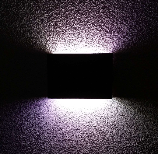
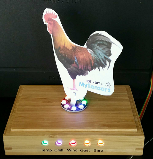
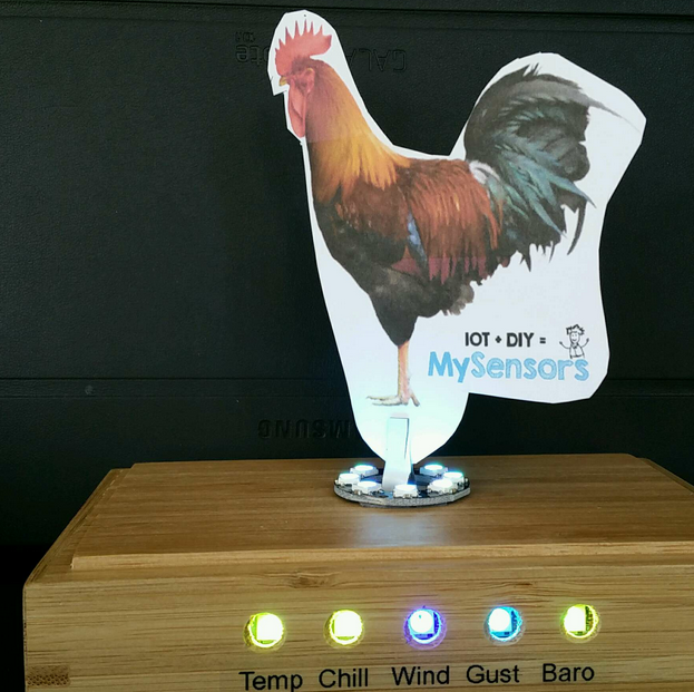
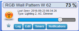
      I made a few changes to my Wall mounted 'mood light' and translated it to MySensors v2.
      0_1474615675050_upload-71b7410c-eae1-43a3-abf8-d074aff5058a

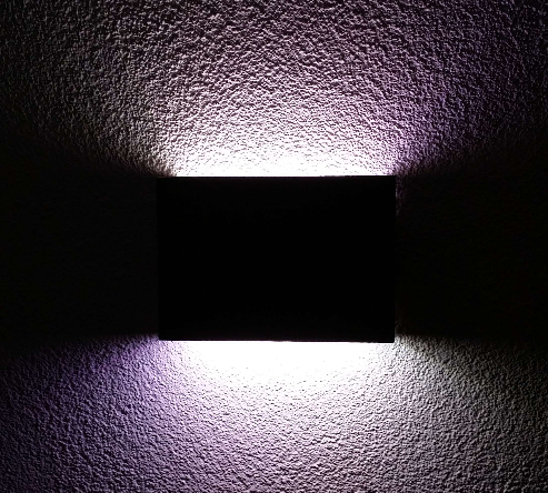
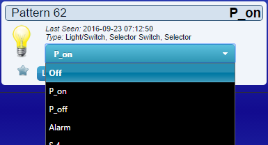
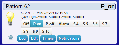
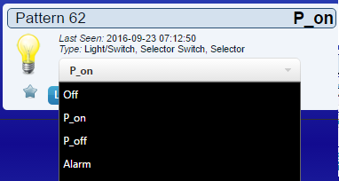
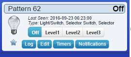
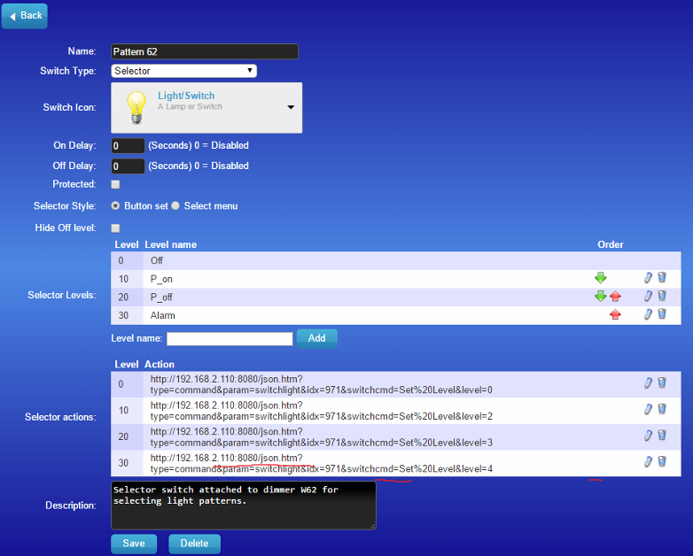
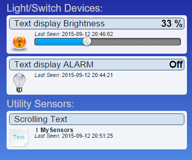
      The sketch shows an example of using a Domoticz selector switch attached to a dimmer (V_PERCENTAGE) to switch between the different light patterns (line 413). I'm pretty sure you can use this trick for more controllers.
      0_1474615943349_upload-f05ed149-c991-4e54-84df-ef1585d32ed9

      /*
       PROJECT: MySensors / RGB light NEOPIXEL
       PROGRAMMER: AWI
       DATE: october 10, 2015/ last update: september 20, 2016
       FILE: AWI_Wall_LIght_x.ino
       LICENSE: Public domain
      
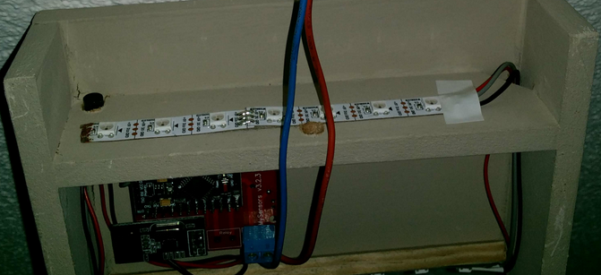
       Hardware: Nano and MySensors 2.0, Wall light 16 WS2812B leds (neopixel)
      		
       Special:
      	uses Fastled library with NeoPixel (great & fast RBG/HSV universal library) 			https://github.com/FastLED/FastLED
      	
       SUMMARY:
      	
      	Different patterns and brightness settings
      	
      	Button switches on/off and cycles through all Color patterns on long press
      	
       Remarks:
      	Fixed node-id
      	
       Change log:
       20160915 - Updated to MySensors 2.0
       20160920 - Changed state change to dimmer i.s.o. switch()
      
      */
      //****  MySensors *****
      // Enable debug prints to serial monitor
      #define MY_DEBUG 
      #define MY_RADIO_NRF24										// Enable and select radio type attached
      //#define MY_RF24_CHANNEL 80								// radio channel, default = 76
      
      #define MY_NODE_ID 62
      #define NODE_TXT "W 62"										// Text to add to sensor name
      
      // #define MY_RF24_CE_PIN 7									// Ceech board, 3.3v (7,8)  (pin default 9,10)
      // #define MY_RF24_CS_PIN 8
      
      // helpers
      #define LOCAL_DEBUG											// enable if print wanted 
      
      #ifdef LOCAL_DEBUG
      #define Sprint(a) (Serial.print(a))							// macro as substitute for print, enable if no print wanted
      #define Sprintln(a) (Serial.println(a))						// macro as substitute for println
      #else
      #define Sprint(a)										
      #define Sprintln(a)
      #endif


      #include <SPI.h>											// My Sensors
      #include <MySensors.h>
      
      #include <FastLED.h>										// https://github.com/FastLED/FastLED
      #include "Button.h"											// https://github.com/JChristensen/Button
      
      const int stripPin = 5 ;									// pin where 2812 LED strip is connected
      const int buttonPin = 4 ;									// push button
      const int numPixel = 16 ;									// set to number of pixels (x top / y bottom)
      
      const int RGB_LightChild = 0 ;								// Child Id's, standard light child on/off/ dim
      const int RGB_RGBChild = 1 ;								// RGB light child (on/off/dim/color, if controller supports V_RBG))
      const int RGB_SolidColorChild = 2 ;							// when set, node reads Color text from ColorTextChild
      const int RGB_TextColorChild = 3 ;							// Holds Text value for color (custom colors from controller)
      const int RGB_AlarmPatternChild = 4 ;						// Switches to alarm status
      const int RGB_NextPatternChild = 5 ;						// Move to next pattern when set
      
      CRGB leds[numPixel];
      
      // Kelving colors: Light & daylight (in Fastled reference only)
      /// 1900 Kelvin Candle=0xFF9329 /* 1900 K, 255, 147, 41 */,
      /// 2600 Kelvin Tungsten40W=0xFFC58F /* 2600 K, 255, 197, 143 */,
      /// 2850 Kelvin Tungsten100W=0xFFD6AA /* 2850 K, 255, 214, 170 */,
      /// 3200 Kelvin	Halogen=0xFFF1E0 /* 3200 K, 255, 241, 224 */,
      /// 5200 Kelvin CarbonArc=0xFFFAF4 /* 5200 K, 255, 250, 244 */,
      /// 5400 Kelvin HighNoonSun=0xFFFFFB /* 5400 K, 255, 255, 251 */,
      /// 6000 Kelvin DirectSunlight=0xFFFFFF /* 6000 K, 255, 255, 255 */,
      /// 7000 Kelvin OvercastSky=0xC9E2FF /* 7000 K, 201, 226, 255 */,
      /// 20000 Kelvin ClearBlueSky=0x409CFF /* 20000 K, 64, 156, 255 */
      
      char setRGBvalue[] = "FFC58F";		 						// Controller sent RGB value, default tungsten40W
      uint16_t curBrightness = 0x7F, setBrightness = 0x7F ;		// Brightness globals (actualBrightness)
      unsigned long updateBrightnessDelay, lastBrightnessUpdate ; // Brightness timers
      int RGBonoff ;												// OnOff flag
      
      enum { pSolid, pOff, pOn, pAlarm, pFire, pFire2, pCandle, pCircle, pSinelon, pRainbow}  ;	// Pattern states (stored in int for convenience)
      const int lastPatternIdx = pRainbow + 1 ;					// use last pattern for patterncount
      int curPattern = pSolid ;									// current pattern
      int setPattern = pSolid ;									// set pattern (controller)
      unsigned long updatePatternDelay, lastPatternUpdate ;		// Pattern timers
      
      unsigned long idleTimer = millis() ;						// return to idle timer
      const unsigned long idleTime = 10000UL;					// return to idle after 10 secs
      
      const unsigned long dimTime = 1000UL;						// dim period
      
      const unsigned long heartbeatInterval = 1 * 60UL * 1000UL ;	// heartbeatinterval, just to let the controller know I am alive
      unsigned long heartbeatCounter = 0 ;
      
      MyMessage lightRGBMsg(RGB_LightChild,  V_RGB);				// standard messages, light
      MyMessage lightdimmerMsG(RGB_LightChild ,V_DIMMER);	
      MyMessage lightOnOffMessage(RGB_LightChild, V_STATUS);
      
      Button myBtn(buttonPin, true, true, 20);					//Declare the button (pin, pull_up, invert, debounce_ms)
      
      // Simple state machine for button state
      enum {sIdle, sBrightness, sPattern} ;						 // simple state machine for button press
      int State ;
      
      void setup() {
      	FastLED.addLeds<WS2812B, stripPin, GRB >(leds, numPixel); 	// initialize led strip (NEOPIXEL =WS...)
      	for(int i = 0 ; i < 6 ; i++) {							// get color value from EEPROM (6 char)
      		setRGBvalue[i] = loadState(i) ;
      		}
      	setLightPattern(pSolid, 0) ;							// default controller Solid 
      	FastLED.show();
      	State = sIdle ;											// Initial state
      	//randomSeed(analogRead(0));
      }


      void presentation(){
      // MySensors
      	sendSketchInfo("AWI RGB Wall " NODE_TXT, "2.0");
      	present(RGB_RGBChild, S_RGB_LIGHT, "RGB Wall RGB " NODE_TXT);// present to controller
      	present(RGB_LightChild, S_LIGHT, "RGB Wall Light " NODE_TXT);
      	present(RGB_SolidColorChild, S_LIGHT, "RGB Set Solid color (text) " NODE_TXT);
      	present(RGB_TextColorChild, S_INFO, "RGB Wall textcolor " NODE_TXT);	
      	present(RGB_AlarmPatternChild, S_BINARY, "RGB Wall Alarm " NODE_TXT);
      	present(RGB_NextPatternChild, S_DIMMER, "RGB Wall Pattern " NODE_TXT);
      }


      // read button and act accordingly
      // short press: on/off
      // longer press: set patterns with following short press
      // long press: set brightness increase 
      void loop() {
      	myBtn.read();               							//Read the button (only read)
      	unsigned long now = millis(); 							// loop timer reference
      	switch (State) {
      		case sIdle:											// default state, browse through patterns
      			if (myBtn.wasReleased()){						// light on/ off in idle
      				RGBonoff = !RGBonoff ;						// invert light state
      				setLightBrightness((RGBonoff == 1)?setBrightness:0, dimTime);
      				send(lightOnOffMessage.set(RGBonoff));	// and update controller	
      			} else if (myBtn.pressedFor(800)){				// move to Pattern update state with long press
      				idleTimer = now ;							// return to idle after ...
      				State = sPattern ;
      			}
      			break ;
      		case sPattern:										// entered after long press
      			if (myBtn.pressedFor(4000)){					// when press even longer move to Brightness update
      				State = sBrightness ;
      			} else if (myBtn.wasPressed()){
      				setPattern = (setPattern + 1) % lastPatternIdx ;  // increase pattern and wrap
      				setLightPattern((setPattern), 500 );
      				idleTimer = now ;
      			} else if ( now > idleTime + idleTimer  ){		// return to idle after ...
      				State = sIdle ;
      			}
      			break ;
      		case sBrightness:									// entered after looong press
      			if (myBtn.wasPressed()){							// if pressed again increase brightness
      				setLightBrightness((curBrightness+0x1F) % 0xFF, 0) ; // increase brightness and wrap (0..0xFF)
      				idleTimer = now ;
      			} else if ( now > idleTime + idleTimer  ){		// return to idle after ...
      				State = sIdle ;
      			}
      			break ;
      		default :
      			State = sIdle ;
      			break ;
      		}
      	updateLightBrightness();								// update Brightness if time
      	updateLightPattern();									// update Pattern if time
      	if ( now > heartbeatCounter  + heartbeatInterval){		// heartbeat every hour
      	    sendHeartbeat();
      		heartbeatCounter = now ; 
      		}
      	}
      
      // Sets the light brightness, takes value and time (ms) as input
      void setLightBrightness(int newBrightness, unsigned long updateTime){
      	// global: curBrightness, actualBrightness, updateBrightnessDelay
      	updateBrightnessDelay = updateTime / 0xFF ;				// delay = time / max steps
      	curBrightness = newBrightness ;							// set curBrightness to new value, rest is done in update
      	}	
       
      // Update the light brightness if time
      void updateLightBrightness(){
      	// global: curBrightness, actualBrightness, updateBrightnessDelay, lastBrightnessUpdate ;
      	static byte actualBrightness ;							// store real brightness state for slow dim
      	unsigned long now = millis() ;
      	if (now > lastBrightnessUpdate + updateBrightnessDelay){// check if time for update
      		if ( actualBrightness > curBrightness) {
      			FastLED.setBrightness( actualBrightness-- );
      			FastLED.show();
      		} else if ( actualBrightness < curBrightness){
      			FastLED.setBrightness( actualBrightness++ );
      			FastLED.show();
      			}
      		lastBrightnessUpdate = now ;
      		}
      	}
      
      // **** Pattern routines *****
      // Sets and initializes the light pattern if nescessary
      void setLightPattern( int newPattern, unsigned long updateDelay){
      	// global: curPattern, updatePatternDelay
      	static int lastPattern = pSolid ;						// last pattern for pOn / pOff virtual patterns
      	if (newPattern == pOff) lastPattern = curPattern ;		// remember last pattern
      	if (newPattern == pOn) curPattern = lastPattern ;		// only for pOn switch to last pattern
      	else curPattern = newPattern ;
      	updatePatternDelay = updateDelay ;						// delay for next pattern update, can be changed in pattern 
      	switch(curPattern){
      		case pSolid:										//  solid is set value in all pixels (and on)
      			for(int i = 0 ; i < numPixel ; i++) leds[i] = strtol( setRGBvalue, NULL, 16);
      			setLightBrightness(setBrightness, dimTime) ;	// slow dim to on
      			FastLED.show();
      			break ;
      		case pOn:											//  On is set Brightness in all pixels
      			setLightBrightness(setBrightness, dimTime) ;		// slow dim to on
      			FastLED.show();
      			break ;
      		case pOff:											//  off state all pixels off (add dim and pOn)
      			setLightBrightness(0, dimTime) ; 					// slow dim to off
      			FastLED.show();
      			break ;
      		case pCircle:										//  all pixels off
      			for(int i = 0 ; i < numPixel ; i++) leds[i] = 0 ;
      			for(int i = 0 ; i < 2 ; i++){
      				leds[i] = strtol( setRGBvalue, NULL, 16) ; // 1 pixel on
      				}
      			FastLED.show();
      			break ;
      		default :
      			setLightBrightness(setBrightness, dimTime) ;	// slow dim to on
      			FastLED.show();
      			break ;
      			}
      	}	
      
      // Update the light pattern when time for it
      void updateLightPattern(){
      	// global: curPattern, updatePatternDelay, lastPatternUpdate
      	unsigned long now = millis() ;
      	if (now > lastPatternUpdate + updatePatternDelay){		// check if time for update
      		switch (curPattern) {
      			case pAlarm:									// flash light
      				patternAlarm();
      				break ;
      			case pFire:										// wild fire
      				patternFire();
      				break ;
      			case pFire2:									// cosy fire
      				patternFire2();
      				break ;
      			case pCandle:									// flame
      				patternCandle();
      				break ;
      			case pCircle:									// flame
      				patternCircle();
      				break ;
      			case pRainbow:									// rotating rainbow
      				patternRainbow();
      				break ;
      			case pSinelon:									// rotating rainbow
      				patternSinelon();
      				break ;
      			case pSolid:									// do nothing fall through
      			case pOff:
      			case pOn:
      			default	:										// def	
      				break ;
      			}
      		lastPatternUpdate = now ;
      		}
      	}
      
      // Define the different patterns
      // Alarm - intermittent white and red color, full intensity, intermittent top & bottom half
      void patternAlarm() {
          static boolean topBot ;									// indicates direction for next entry
      	const CRGB colorTop = CRGB(0xFF, 0, 0 );				// red color
      	const CRGB colorBottom = CRGB(0xFF, 0xFF, 0xFF );		// white color
      	FastLED.setBrightness(0xFF);							// set the strip brightness to max for Alarm
      	for(int i=0; i <= (numPixel / 2 - 1) ; i++) {			// for half of strip size
      		leds[i] = topBot?colorTop:colorBottom ;	
      		leds[i+ (numPixel/2)] = topBot?colorBottom:colorTop ;
      		}
      	topBot = !topBot ;										// switch direction
      	FastLED.show();
      	}
      
      // Simulate fire with red color, varying number of leds intensity & tempo
      void patternFire() {
          byte numberLeds = random(0,numPixel);					// start number and end of led's for flickering
          int lum = ((random(100,255) * curBrightness)) / 0xFF ;	// set brightness and scale
          CRGB color = CRGB(200, random(70,230),0 );				// get red color with varying green
          for(int i=0; i <= numberLeds; i++) {
            leds[i] = color ;
            FastLED.setBrightness(lum);							// set the strip brightness
            FastLED.show();
            wait(random(0,10));									// (blocking, need to be changed)
          }
          updatePatternDelay = 100 ; 
      }
      
      // Simulate fire with red color and varying intensity & tempo
      void patternFire2() {
          CRGB color = CRGB(200, random(100,150),0);				// get red color with varying green
          for (byte p=0; p < numPixel; p++) {
            leds[p] = color;
          }
          FastLED.setBrightness((random(50,255) * curBrightness)/ 0xFF );	// set Brightness and scale
          FastLED.show();
          updatePatternDelay = random(20,300);					// variable delay
      }
      
      // Simulate candle based on fire with red color, varying number of leds intensity & tempo
      void patternCandle() {
          byte numberLeds = random(0,numPixel);					// start number and end of led's for flickering
          byte lum = ((random(100, 255) * curBrightness)/ 0xFF);	// set brightness
          CRGB color = CRGB(200, random(90,130),0 );				// get red color with varying green
          for(int i=0; i <= numberLeds; i++) {
            leds[i] = color ;
            FastLED.setBrightness(lum);							// set the strip brightness
            FastLED.show();
            wait(random(5,10));									// (blocking, need to be changed)
          }
          updatePatternDelay = 100 ; 
      }
      
      // a colored dot sweeping back and forth, with fading trails, adapted from Fastled sinelon
      void patternSinelon()
      {
      	fadeToBlackBy( leds, numPixel, 10);						// fade all leds a small amount 
      	int pos = beatsin8(25,0,numPixel);						// get a new position for the led (BPM = 13, min, max, )
      	leds[pos] += strtol( setRGBvalue, NULL, 16);
      	FastLED.show();
      	updatePatternDelay = 2 ;
      }
      
      
      // Rotate all Leds with current content and trail
      void patternCircle() {
      	static int currentLed ;									// indicated current led to light
      	// CRGB tempLed = leds[0];					 			// temporary variable for color
      	fadeToBlackBy( leds, numPixel, 128);					// fade all leds for trail..
      	leds[currentLed] = strtol( setRGBvalue, NULL, 16);		// set to current color
      	currentLed = (currentLed + 1) % numPixel ;				// wrap
          FastLED.show();
          updatePatternDelay = 100 ; 
      }
      
      void patternRainbow() {
      	static uint16_t hue ;									// starting color
      	FastLED.clear();
      	// for(hue=10; hue<255*3; hue++) {
      	hue = (hue+1) % 0xFF ;									// incerease hue and wrap
      	fill_rainbow( leds, numPixel , hue /*static hue value */, 1);// set a rainbow from hue to last in stepsize 1
      	FastLED.show();
      	updatePatternDelay = 100 ;
      	}
      
      // Incoming messages from MySensors
      void receive(const MyMessage &message) {
      	int ID = message.sensor;
      	Serial.print("Sensor: ");
      	Serial.println(ID);
      	switch (ID){
      		case RGB_LightChild:								// same behaviour as RGB child/ fall through
      		case RGB_RGBChild:									// if controller can handle V_RGB
      			if (message.type == V_RGB) {					// check for RGB type
      				strcpy(setRGBvalue, message.getString());	// get the payload
      				setLightPattern(pSolid, 0);					// and set solid pattern 
      			} else if (message.type == V_DIMMER) {			// if DIMMER type, adjust brightness
      				setBrightness = map(message.getInt(), 0, 100, 0, 255);
      				setLightBrightness(setBrightness, dimTime) ;
      			} else if (message.type == V_STATUS) {			// if on/off type, toggle brightness
      				RGBonoff = message.getInt();
      				setLightBrightness((RGBonoff == 1)?setBrightness:0, dimTime);
      			}
      			break ;
      		case RGB_SolidColorChild:							// request color from controller
      			if (message.type == V_STATUS) {					// if get color from text child
      				request(RGB_TextColorChild, V_TEXT);
      				setLightPattern(pSolid, 0);					// and set solid pattern (if not alre)
      				}
      			break ;
      		case RGB_TextColorChild:							// Text color from controller
      			if (message.type == V_TEXT) {					// if get color from text child
      				strcpy(setRGBvalue, message.getString());	// get the payload
      				for(int i = 0 ; i < 6 ; i++) {				// save color value to EEPROM (6 char)
      					saveState(i, setRGBvalue[i]) ;}			// Save to EEPROM
      				}
      			break ;
      		case RGB_AlarmPatternChild:							// set Alarm pattern
      			if (message.type == V_STATUS) {					// if get color from text child
      				if (message.getInt() == 1){
      					setLightPattern(pAlarm, 500);			// set slow alarm pattern
      				} else {
      					setLightPattern(setPattern, 0);			// and reset pattern
      					FastLED.setBrightness(setBrightness);
      					}
      				}
      			break ;
      		case RGB_NextPatternChild:							// next pattern
      			if (message.type == V_PERCENTAGE) {				//  Percentage indicates the pattern
      				setPattern = map(message.getInt(), 0, 100, 0, 15) % lastPatternIdx  ; // mapper dimmer value to state 0..9  and wrap
      				setLightPattern((setPattern), 500 );
      				Sprint("Pattern: ") ; Sprintln(setPattern) ;
      			} else if (message.type == V_STATUS){			// if off switch pattern to default == 0
      				setPattern = 0  ;
      				setLightPattern((setPattern), 500 );
      				Sprint("Pattern: ") ; Sprintln(setPattern) ;
      			}
      			break ;
      		}
          FastLED.show();
      	dispRGBstat();
       	}
      // debug	
      // display the status of all RGB: controller, requested, real
      void dispRGBstat(void){
          Serial.print(" Color: "); Serial.print(setRGBvalue); 
          Serial.print(" Brightness: "); Serial.println(setBrightness);
      	}
      
      
      posted in My Project
      AWI
      AWI
    • Using the "Selector switch" in Domoticz (tutorial)

      Domoticz features a special switch type named "Selector switch" . This switch type can serve many MySensors purposes. In this walk through it is used for selecting different light patterns in my Wall mounted 'mood light'.
      A "button set"
      0_1474613749068_upload-5c2bdf83-e135-4b01-a842-f8bf16b2c468

      or "select menu"
      0_1474613812167_upload-ff85302a-8b41-4033-8654-f3d85a0a2351

      Essentially it is (or can be) a switch which controls another device. In this case I use it to control a dimmer. Let's start.

      1. Create a virtual hardware device (if you have not already done so before)

      0_1474614096927_upload-fdbc81ca-84db-4f95-8a4c-36d9434bde72

      1. Create a new "Virtual Sensor" with type "Selector Switch" by pressing the "Create Virtual Sensors" button.
        0_1474614259118_upload-dfadaa31-681c-4100-9f65-7e9b77705850
        you can also use the "Manual Light/Switch" button in the "Switches" tab.
        0_1474614203400_upload-fc866b82-9544-43ac-ad46-280721ae59eb

      This will create a new Virtual selector switch.
      0_1474614396110_upload-9189aef8-4502-43ce-bbb5-386dc84d6cb1

      I will use this to control a dimmer device which output is used to set the light patterns in the mood light
      0_1474614481046_upload-803f08fb-dda1-4142-8677-d9fb706ad9bd

      1. In the devices tab find the "Dimmer you want the Selector attached to (in this case RGB Wall Pattern W 62" with index 971
        0_1474614623251_upload-a4eb98fa-e59f-4915-a4aa-a970f8ab57c6

      "Edit" the newly created Selector switch and for each of the selector states attach a command to be executed.

      The commands here can be pretty much anything but here I used the Domoticz JSON command to set the Dimmer to one of the 16 possible states (Yes, a dimmer can only asume 16 states). You need to put your own domoticz URL/IP and port number in there. "Idx" is the dimmer device index from the previous step.

      A maximum of 10 switch values can be assigned
      ❗ don't forget to save 😓

      0_1474614939249_upload-825741bf-c2ee-4538-ad15-7881f12fc4ca
      I deliberately did not set "level 1" , because this translates to "0" and is associated with the off state in my case (room light)

      for the copycats (don't forget to include your own values):

      http://192.168.2.110:8080/json.htm?type=command&param=switchlight&idx=971&switchcmd=Set%20Level&level=0
      

      That's it. Now when you press a selector button it switches the dimmer value.

      In your sketch you can translate the dimmer values to differenct actions. Have a look at the Wall light sketch for an example.

      posted in Domoticz
      AWI
      AWI
    • USB ISP programmer with Small AA sensor node

      Programming a bare ATMEGA can be quite cumbersome. Using a cheap USB ISP programmer and the Arduino IDE simplifies things.

      0_1456997858419_upload-6532ca59-67fd-4ee5-a524-206a11ab024c

      I equipped The multi purpose Slim 2AA Battery Node with a ZIF socket and resonator (only needed if the bare ATMEGA328 is pre programmed to need an external crystal) and voila: a €6 USB ISP programmer for your MySensors nodes!

      0_1456998326251_upload-309e3269-313f-42dc-9139-0731e45111c7
      0_1456997605485_upload-9a7eedf6-d78e-4c14-ad63-02b624761a87

      (notice that I mounted the components on the back side of the board, in fact most are not actually needed)

      Select the right programmer in the Arduino IDE and you can set fuses and upload you preferred bootloader.

      posted in My Project
      AWI
      AWI
    • Remote debug messages with V_TEXT

      Sometimes I want to have debug information from my nodes while these are not connected through serial. I.e. to discover "random" freezes of an outside weather node. So I rewrote a familiar macro

      #define LOCAL_DEBUG
      #ifdef LOCAL_DEBUG
      	#define Sprint(a) (Serial.print(a))						// macro as substitute for print, enable if no print wanted
      	#define Sprintln(a) (Serial.println(a))					// macro as substitute for println
      #else														// no print
      	#define Sprint(a)
      	#define Sprintln(a)
      #endif
      

      to include "remote debugging" by using "sprintf()" (formatted print). It is a (working) first attempt with limitations. Suggestions for improvement are more than welcome. The debug information is sent with V_TEXT and needs to be handled by the controller or a "logging node" (I will publish one soon)

      // Helper for Debug:  1 = Serial debug output ; 2 = V_TEXT remote output ; else no debug
      // Use Formats described in fprint() : http://www.cplusplus.com/reference/cstdio/printf/  
      // Example: 	Printf("Temp %2d Hum %2d\n", temperature, humidity);
      // warning: max print size < 24 ; float = NOT supported in Arduino, you need to convert it yourself, ie. dtostrf(Temperature, 5, 2, tempBuf)
      #define _DEBUG 2												// 0 = no output ; 1 = Serial debug output ; 2 = V_TEXT remote output 
      #if _DEBUG == 1													// Serial output
      	char printBuf[24] ;											// need temporary buffer
      	#define Printf(...) { sprintf(printBuf, __VA_ARGS__) ; Serial.print(printBuf);}	// macro to substitute Printf()
      #elif _DEBUG == 2												// if remote debug you need to define a child and present it to the controller
      	#define DEBUG_CHILD_ID 10									// Child id of V_TEXT
      	MyMessage debugMsg(DEBUG_CHILD_ID, V_TEXT);					// get the debug message ready
      	char printBuf[24] ;											// need temporary buffer
      	#define Printf(...) { sprintf(printBuf, __VA_ARGS__) ; send(debugMsg.set(printBuf)); }	// macro to substitute Printf()						
      #else															// No debug wanted
      	#define Printf(...)										
      #endif
      
      posted in Development
      AWI
      AWI
    • Scrolling Text sensor node with new V_TEXT

      Another experiment for the V_TEXT variable/ sensor. Including brightness & speed setting and special Alarm function.
      upload-3aa973f9-d6cf-41a5-8b59-2241311896b0
      A scrolling display to let the family now that the dog needs walking... nothing more than 1 nano, 8 (or whatever number) of displays with max7219 controller upload-f2290f64-a15d-48c9-8420-ab65e481a492 
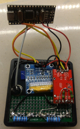
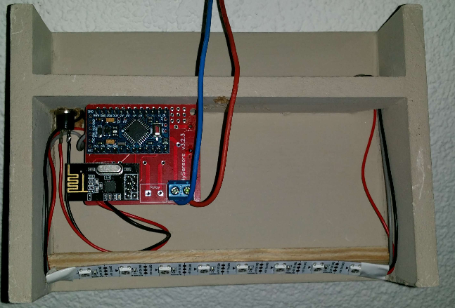
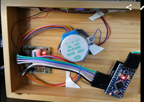
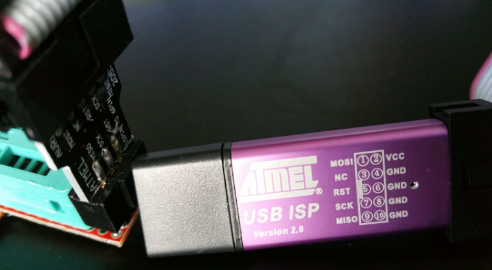
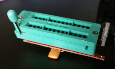
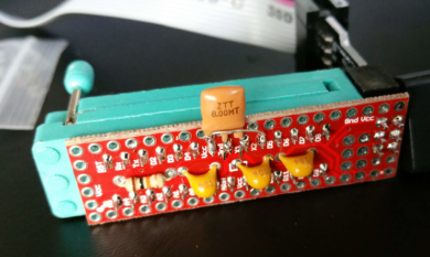
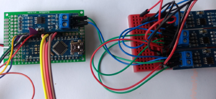
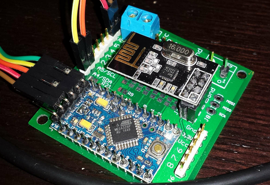
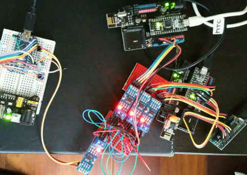
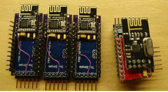
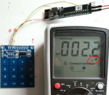
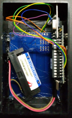
a radio and a few cables
      upload-4c163020-edac-4bc5-b3bf-50f1f3cccd24
      Total cost: €18 (with 8 displays)

      in Domoticz:
      upload-868a0c0c-a44d-480f-940c-e0378716ebd3
      Built around the very versatile "Parola" driver library

      (I will upload a video when I know how to .. ;-))
      MySensors - Scrolling text display – 00:05
      — Ad Imhoff

      /*
       PROJECT: MySensors / Scrolling Text display
       PROGRAMMER: AWI
       DATE: september 12, 2015/ last update: september 12, 2015
       FILE: AWI_scroll_MAX.ino
       LICENSE: Public domain
      
       Hardware: tbd ..Ceech - ATmega328p board w/ NRF24l01
      	and MySensors 1.5 ()
      		
      Special:
      	Need to use MySensors development edition 
      	
      SUMMARY:
      	3 S_xx devices for scrolling text
      	- Displays a scrolling text from a "V_TEXT" variable
       	- additional dimmer sensor for controlling display brightness
      	- 'Alarm' switch. If "On", overrides the text display to display ALARM message
      	- You can also input messages from the Serial monitor (testing)
      	Uses excellent MD_MAX72XX library 
       Remarks:
      	Fixed node-id
      */
      
      // Use the MD_MAX72XX library to scroll text on the display with the use of the callback function 
      // to control what is scrolled on the display text.
      // You need to set the used display in the library MD_MAX72XX.h
      // User can enter text on the serial monitor and this will display as a
      // Speed for the display is controlled by a pot on SPEED_IN analog in.
      #include <MD_MAX72xx.h>						// multipurpose library for MAX72xx diaplay driver  https://parola.codeplex.com/
      #include <MySensor.h>          				// Mysensor network
      #include <SPI.h>
      #include <Time.h>   						//http://playground.arduino.cc/Code/Time
      #define	USE_POT_CONTROL	0					// enable Scroll speed  potentiometer
      #define	PRINT_CALLBACK	0
      
      // Macro to simplify serial print
      #define	PRINT(s, v)	{ Serial.print(F(s)); Serial.print(v); }
      
      // Define the number of devices we have in the chain and the hardware interface
      // need to be adapted to your setup
      const int MAX_DEVICES = 8 ;					// number of 8x8 displays
      const int CLK_PIN = 7 ; 					// SPI like clock
      const int DATA_PIN = 8 ;					// SPI like data
      const int CS_PIN = 6 ; 						// SPI like select
      
      // Parola is able to use SPI hardware interface, not testted in combination with MySensors
      // MD_MAX72XX mx = MD_MAX72XX(CS_PIN, MAX_DEVICES);
      // now use Arbitrary pins
      MD_MAX72XX mx = MD_MAX72XX(DATA_PIN, CLK_PIN, CS_PIN, MAX_DEVICES);	// instantiate one display chain
      
      // Scrolling parameters, you can attach normal potentiometer to A5, Vcc, Gnd
      #if USE_POT_CONTROL
      const int SPEED_IN = A5 ;
      #else
      const int SCROLL_DELAY = 20 ;				// in milliseconds
      #endif // USE_POT_CONTROL
      
      const int CHAR_SPACING = 1 ;				// pixels between characters
      
      // MySensors constants & variables
      const byte nodeId = 51 ;					// MySensors fixed node id
      const byte messageCHILD = 8 ;				// Text from ControllerLCD
      const byte brightnessChild = 9 ;			// Brightness of display
      const byte alarmChild = 10 ;				// Display Alarm text (overrides normal text)
      boolean timeReceived = false ;				// Flag to indicate time received
      // Display constants & variables
      byte textBrightness = 1 ;					// brightness of display (between 0 - MAX_INTENSITY (0xF)
      byte textOnOff = true ;						// textOnOff = ! shutdown
      boolean textAlarm = false ;					// Alarm (switch S_BINARY)
      // Global message buffers shared by MySensors and Scrolling functions
      const int BUF_SIZE = 25 ;					// max payload for MySensors(NRF24l01)
      char curMessage[BUF_SIZE];					// current displayed message
      char newMessage[BUF_SIZE];					// next message to be displayed if available
      bool newMessageAvailable = false ;			// new message available flag
      uint16_t	scrollDelay;					// in milliseconds
      
      // *** Definition and initialisation
      // define the MySensor network (1.5)
      MyTransportNRF24 transport(9,10); 			// Sensoduino (8,7) Ceech board, 3.3v (7,8)  (pin default 9,10)
      MySensor gw(transport);  
      // Initialize messages for sensor network
      MyMessage textMsg(messageCHILD, V_TEXT);	// message for Sending Text to Controller
      
      
      /* MD_MAX72XX functions: can be found in the documentation for the library,
       * no need to customtize callback & scroll routines (unless you want to...)
      */
      uint8_t scrollDataSource(uint8_t dev, MD_MAX72XX::transformType_t t)
      // Callback function for data that is required for scrolling into the display
      {
        static char		*p = curMessage;
        static uint8_t	state = 0;
        static uint8_t	curLen, showLen;
        static uint8_t	cBuf[8];
        uint8_t colData;
      
        // finite state machine to control what we do on the callback
        switch(state)
        {
          case 0:	// Load the next character from the font table
            showLen = mx.getChar(*p++, sizeof(cBuf)/sizeof(cBuf[0]), cBuf);
            curLen = 0;
            state++;
      
            // if we reached end of message, reset the message pointer
            if (*p == '\0')
            {
              p = curMessage;			// reset the pointer to start of message
              if (newMessageAvailable)	// there is a new message waiting
              {
                strcpy(curMessage, newMessage);	// copy it in
                newMessageAvailable = false;
              }
            }
            // !! deliberately fall through to next state to start displaying
      
          case 1:	// display the next part of the character
            colData = cBuf[curLen++];
            if (curLen == showLen)				// end of character insert interchar space
            {
              showLen = CHAR_SPACING;
              curLen = 0;
              state = 2;
            }
            break;
      
          case 2:	// display inter-character spacing (blank column)
            colData = 0;
            curLen++;
            if (curLen == showLen)
              state = 0;
            break;
      
          default:
            state = 0;
        }
      
        return(colData);
      }
      
      // Callback (not used here)
      void scrollDataSink(uint8_t dev, MD_MAX72XX::transformType_t t, uint8_t col){
      // Callback function for data that is being scrolled off the display
      #if PRINT_CALLBACK
      	Serial.print("\n cb ");
      	Serial.print(dev);
      	Serial.print(' ');
      	Serial.print(t);
      	Serial.print(' ');
      	Serial.println(col);
      #endif
      }
      
      // non-blocking text display to be used in loop (call frequently)
      void scrollText(void){
      	static uint32_t	prevTime = 0;
      	if (millis()-prevTime >= scrollDelay){					// Is it time to scroll the text?
      		mx.transform(MD_MAX72XX::TSL);						// scroll along - the callback will load all the data
      		prevTime = millis();								// starting point for next time
      		}
      	}
      
      // sets the scroll delay (read from potentiometer if enabled)
      uint16_t getScrollDelay(void){
      #if USE_POT_CONTROL
      	uint16_t t = analogRead(SPEED_IN);
      	t = map(t, 0, 1023, 25, 250);
      	return(t);
      #else
      	return(SCROLL_DELAY);
      #endif
      	}
      
      void setup(){
      	// set up the display first
      	mx.begin();												// initialize display chain					
      	mx.setShiftDataInCallback(scrollDataSource);			// define function to get the scrolldata (returned as int8)
      	//mx.setShiftDataOutCallback(scrollDataSink); 			// not used
      	mx.control(MD_MAX72XX::INTENSITY, 0x01);
      #if USE_POT_CONTROL											// initialize speed potentiometer if enabled
      	pinMode(SPEED_IN, INPUT);
      #else
      	scrollDelay = SCROLL_DELAY;
      #endif
      
      	strcpy(curMessage, "I \x03 MySensors ");				// first message on display
      	newMessage[0] = '\0';									// new message initialized to empty
      	// Setup MySensors 
         //Serial in Sensor network = 115200
          gw.begin(incomingMessage, nodeId); 						// this node is 51 fixed 
          //Send the sensor node sketch version information to the gateway
          gw.sendSketchInfo("AWI Scroll MAX 51", "1.1");
       	gw.present(messageCHILD, S_INFO, "Text line Scroll");	// new S_type 20150905 (not know by domoticz)
       	gw.present(alarmChild, S_BINARY, "Alarm display");		// to display alarm text
      	gw.present(brightnessChild, S_DIMMER, "Text brightness"); // new S_type 20150905 (not know by domoticz)
          //gw.send(textMsg.set("-"));							// initialize the V_TEXT at controller for sensor to none (trick for Domoticz)
      	gw.request(messageCHILD, V_TEXT, 0); 					// request value from controller
      	// Initializations
          gw.requestTime(receiveTime);							// get the time from controller (handled by receiveTime)
      	}
      
      // loop only uses non-blocking functions
      void loop() {
      	gw.process();
      	static unsigned long lastUpdate ;						// Static hold the last update time
      	unsigned long now = millis();
      	scrollDelay = getScrollDelay();							// update scroll delay from potentiometer
      	readSerial();
          // Check for new conditions & ask for new information from controller every 10 seconds
          if (now-lastUpdate > 10000){
      		if (textAlarm){										// if alarmstatus: override all text and set max intensity
      			strcpy(curMessage, "   ALARM   ");
      			mx.control(MD_MAX72XX::INTENSITY, MAX_INTENSITY);	// set current brightness
      			mx.control(MD_MAX72XX::SHUTDOWN, false) ;
      		} else {											// standard (non Alarm actions)
      			mx.control(MD_MAX72XX::INTENSITY, textBrightness);	// set current brightness
      			mx.control(MD_MAX72XX::SHUTDOWN, textOnOff) ;
      			gw.request(messageCHILD, V_TEXT, 0); 				// request new value from controller
      		}
      		lastUpdate = now;
      	}
      	scrollText();
      }
       
      // This is called when a new time value was received
      void receiveTime(unsigned long controllerTime) {
          Serial.print("Time value received: ");
          Serial.println(controllerTime);
          setTime(controllerTime); 								// time from controller
          timeReceived = true;
      	} 
      
      // This is called when a message is received 
      void incomingMessage(const MyMessage &message) {
      	Serial.print("Message: "); Serial.print(message.sensor); Serial.print(", Message: "); Serial.println(message.getString());
      	if (message.sensor == messageCHILD){
      		if (message.type==V_TEXT) {						// Text content
      		strcpy(newMessage, message.getString());		// copy it in
       			newMessageAvailable = true ;
      		}
      	} else if (message.sensor == alarmChild) {
      		if (message.type==V_STATUS) {					// True/ false content
       			textAlarm = message.getBool()?true:false ;	// set alarmflag
      			Serial.print("TextAlarm: ");
      			Serial.println(textAlarm);
      		}
      	} else if (message.sensor == brightnessChild){
      		if (message.type==V_PERCENTAGE) {				// Level 0..100  content
       			textBrightness = map(message.getInt(),0, 100, 0, MAX_INTENSITY ) ;	// map to brightnesslevel 
      			Serial.print("TextBrightness: ");
      			Serial.println(textBrightness);
      		} else if (message.type==V_STATUS) {			// Display on/off
       			textOnOff = message.getBool()?false:true ;		// set shutdown/ !on/off
      			Serial.print("Text on/off: ");
      			Serial.println(textOnOff);
      		}
      	}
      }
      
      	
      // Testing purposes: input routine character buffer. Reads serial characters in buffer newMessage.
      // sets flag newMessageAvailable to true if completed
      void readSerial(void)
      {
        static uint8_t	putIndex = 0;
      
        while (Serial.available())
        {
          newMessage[putIndex] = (char)Serial.read();
          if ((newMessage[putIndex] == '\n') || (putIndex >= BUF_SIZE-3))	// end of message character or full buffer
          {
            // put in a message separator and end the string
            newMessage[putIndex++] = ' ';
            newMessage[putIndex] = '\0';
            // restart the index for next filling spree and flag we have a message waiting
            putIndex = 0;
            newMessageAvailable = true;
          }
          else
            // Just save the next char in next location
            newMessage[putIndex++];
        }
      }


      posted in My Project
      AWI
      AWI
    • RE: nRf24L01+ connection quality meter

      The sketch for the connection quality meter.

      /*
       PROJECT: MySensors / Quality of radio transmission 
       PROGRAMMER: AWI (MySensors libraries)
       DATE: 20160529/ last update: 20160530
       FILE: AWI_Send.ino
       LICENSE: Public domain
      
       Hardware: ATMega328p board w/ NRF24l01
      	and MySensors 2.0 (Development)
      	
      Special:
      	
      	
      Summary:
      	Sends a radio message with counter each  x time to determine fault ratio with receiver
      Remarks:
      	Fixed node-id & communication channel to other fixed node
      	
      Change log:
      20160530 - added moving average on fail/ miss count 
      */
      
      
      //****  MySensors *****
      // Enable debug prints to serial monitor
      #define MY_DEBUG 
      #define MY_RADIO_NRF24									// Enable and select radio type attached
      #define MY_RF24_CHANNEL 80								// radio channel, default = 76
      
      #define MY_NODE_ID 250
      #define NODE_TXT "Q 250"								// Text to add to sensor name
      
      // #define MY_RF24_CE_PIN 7								// Ceech board, 3.3v (7,8)  (pin default 9,10)
      // #define MY_RF24_CS_PIN 8
      #define DESTINATION_NODE 0								// receiving fixed node id (default 0 = gateway)
      
      #include <SPI.h>
      #include <MySensor.h>  
      
      // display
      #include <Wire.h>											// I2C
      #include <LiquidCrystal_I2C.h>								// LCD display with I2C interface
      
      
      // helpers
      #define LOCAL_DEBUG
      
      #ifdef LOCAL_DEBUG
      #define Sprint(a) (Serial.print(a))						// macro as substitute for print, enable if no print wanted
      #define Sprintln(a) (Serial.println(a))					// macro as substitute for println
      #else
      #define Sprint(a)										// enable if no print wanted -or- 
      #define Sprintln(a)										// enable if no print wanted
      #endif
      
      
      // MySensors sensor
      #define counterChild 0
      
      // send constants and variables
      int messageCounter = 0 ; 
      const int messageCounterMax = 100 ; 					// maximum message counter value 
      const unsigned counterUpdateDelay = 100 ;				// send every x ms and sleep in between
      
      // receive constants and variables
      boolean failStore[messageCounterMax] ;					// moving average stores & pointers
      int failStorePointer = 0 ;
      boolean missedStore[messageCounterMax] ;
      int missedStorePointer = 0 ;
      int newMessage = 0 ;
      int lastMessage = -1 ;
      int missedMessageCounter = 0 ; 							// total number of messages in range (messageCounterMax)
      int failMessageCounter = 0 ; 							// total number of messages in range (messageCounterMax)
      
      // Loop delays
      const unsigned long displayInterval = 1000UL ;			// display update in ms
      unsigned long lastDisplayUpdate = 0 ;					// last update for loop timers
      
      // standard messages
      MyMessage counterMsg(counterChild, V_PERCENTAGE);		// Send value
      
      // ***** LCD
      LiquidCrystal_I2C lcd(0x27, 2, 1, 0, 4, 5, 6, 7, 3, POSITIVE);  // Set the LCD I2C address
      
      void setup() {
      	Wire.begin();  // I2C
          // ** LCD display **
          // LCD 2 lines * 16 char.
          lcd.begin(16, 2);
          lcd.setBacklight(HIGH);
          lcd.setCursor(0, 0);
      	lcd.print("AWI Quality nRF24");
      
      	for(int i= 0 ; i <  messageCounterMax ; i++){		// init stores for moving averages
      		failStore[i] = true ;
      		missedStore[i] = true ;
       	}
      	missedStorePointer = failStorePointer = 0 ;
          delay(1000);
      }
      
      void presentation(){
      // MySensors
      	present(counterChild, S_DIMMER, "Quality counter " NODE_TXT) ;  // counter uses percentage from dimmer value
      }
      
      
      void loop() {
      	// Sprint("count:") ; Sprintln(messageCounter) ;
      	LCD_local_display();
      	missedStore[failStorePointer] = false  ; 			// set slot to false (ack message needs to set) ; 
      	boolean succes = failStore[failStorePointer] = send(counterMsg.setDestination(DESTINATION_NODE).set(failStorePointer), true);  // send to destination with ack
      	if (!succes){
      		failMessageCounter++ ; 
      		Sprint("Fail on message: ") ; Sprint(failStorePointer) ;
      		Sprint(" # ") ; Sprintln(failMessageCounter);
      	}
      	failStorePointer++ ;
      	if(failStorePointer >= messageCounterMax){
      		failStorePointer =  0	;						// wrap counter
      	}
      	wait(counterUpdateDelay) ;							// wait for things to settle and ack's to arrive
      }
      
      void receive(const MyMessage &message) {  				// Expect few types of messages from controller
      	newMessage = message.getInt();						// get received value
      	switch (message.type){
      		case V_PERCENTAGE:
      			missedStore[newMessage] = true ;			// set corresponding flag to received.
      			if (newMessage > lastMessage){				// number of messages missed from lastMessage (kind of, faulty at wrap)
      				Sprint("Missed messages: ") ; Sprintln( newMessage - lastMessage - 1) ;
      				missedMessageCounter += newMessage - lastMessage - 1 ;
      			}
      			lastMessage = newMessage ;
      			break ;
      		default: break ;
      	}
      }
      
      
      // calculate number of false values in array 
      // takes a lot of time, but who cares...
      int getCount(boolean countArray[], int size){
      	int falseCount = 0 ;
      	for (int i = 0 ; i < size ; i++){
      		falseCount += countArray[i]?0:1 ;
      	}
      	return falseCount ;
      }
      
      void LCD_local_display(void){
      /* prints all available variables on LCD display with units
      */
      	
          char buf[17]; 											// buffer for max 16 char display
          lcd.setCursor(0, 0);
          snprintf(buf, sizeof buf, "Failed:%4d %3d%%", failMessageCounter, getCount(failStore, messageCounterMax));
          lcd.print(buf);
          lcd.setCursor(0, 1);
          snprintf(buf, sizeof buf, "Missed:%4d %3d%%", missedMessageCounter, getCount(missedStore, messageCounterMax));
      	lcd.print(buf);
      }
      
      
      posted in My Project
      AWI
      AWI
    • RS485 Stress test

      Just a little experiment on how well the wired RS485 communication is doing. I wired up 4 nano's with RS485, in parallel on the bus, Baud rate to 19200. One node is a gateway the other three are firing an integer every 500-700 ms (random). The gateway catches the values and simply measures missed to received messages.

      Rather messy, but hey it's wired 🙂
      0_1475940887069_upload-7fcbe85a-d054-401c-8cf4-bfde2436d4ca 0_1475940940839_upload-d36f3e4e-33bb-4ec3-8c0a-9ff11afab087

      Error rate is around 5% ! Probably bus collisions ... (I will dig deeper ... and Yes CAN bus would be better, but this can be resolved )

      The Sketches:
      Simple adaption of the example motion sketch

      // MySensors 
      #define MY_DEBUG 												// Enable MySensors debug to serial
      #define MY_PARENT_NODE_ID 0										// define if fixed parent
      #define MY_PARENT_NODE_IS_STATIC
      #undef MY_REGISTRATION_FEATURE									// sketch moves on if no registration
      #define MY_NODE_ID 12											// fixed node number
      #define NODE_TXT "RS485 test 12"								// Text to add to sensor name
      
      // Enable RS485 transport layer
      #define MY_RS485
      
      // Define this to enables DE-pin management on defined pin 
      #define MY_RS485_DE_PIN 2
      
      // Set RS485 baud rate to use
      #define MY_RS485_BAUD_RATE 19200
      
      #include <MySensors.h>
      
      unsigned long SLEEP_TIME = 500; 								// Sleep time between reports (in milliseconds)
      #define CHILD_ID 1   											// Id of the sensor child
      
      // Initialize message
      MyMessage msg(CHILD_ID, V_PERCENTAGE);
      int messageCounter = 0 ;										// Count the outgoing messages for validation (0..99)
      
      
      void setup()  
      {  
      }
      
      void presentation()  {
        // Send the sketch version information to the gateway and Controller
        sendSketchInfo("AWI " NODE_TXT, "1.0");
      
        // Register all sensors to gw (they will be created as child devices)
        present(CHILD_ID, S_PERCENTAGE);
      }
      
      void loop()     
      {     
         	Serial.print(NODE_TXT " message: " );
      	Serial.println(messageCounter);
      	send(msg.set(messageCounter)); 								// Send message to gw 
      	messageCounter = ++messageCounter % 100 ;					// wrap
      	// Send update every SLEEP_TIME
      	sleep(random(SLEEP_TIME, SLEEP_TIME + 200));
      }
      

      Adapted Gateway sketch

      
      // Enable RS485 transport layer
      #define MY_RS485
      
      // Define this to enables DE-pin management on defined pin
      #define MY_RS485_DE_PIN 2
      
      // Set RS485 baud rate to use
      #define MY_RS485_BAUD_RATE 19200
      
      // Enable serial gateway
      #define MY_GATEWAY_SERIAL
      
      
      // Enable inclusion mode
      #define MY_INCLUSION_MODE_FEATURE
      // Enable Inclusion mode button on gateway
      #define MY_INCLUSION_BUTTON_FEATURE
      // Set inclusion mode duration (in seconds)
      #define MY_INCLUSION_MODE_DURATION 60
      // Digital pin used for inclusion mode button
      #define MY_INCLUSION_MODE_BUTTON_PIN  3
      
      // Set blinking period
      #define MY_DEFAULT_LED_BLINK_PERIOD 300
      
      // Flash leds on rx/tx/err
      #define MY_DEFAULT_ERR_LED_PIN 4  // Error led pin
      #define MY_DEFAULT_RX_LED_PIN  5  // Receive led pin
      #define MY_DEFAULT_TX_LED_PIN  6  // the PCB, on board LED
      
      #include <MySensors.h>
      
      const int maxNodes = 20 ;								// maximum number of Nodes for test. Nodes should be numbered from 1..
      int lastValues[20] ; 									// temporary storage of last sent values (index is node number)
      int messageCounter = 0 ;								// total messages
      int messageErrorCounter = 0 ;							// number of errors
      
      void setup() {
        // Setup locally attached sensors
      }
      
      void presentation() {
       // Present locally attached sensors
      }
      
      void loop() {
        // Send locally attached sensor data here
      }
      
      void receive(const MyMessage &message) {  				// messages from node or controller
      	char printBuf[40] ;
      	lastValues[message.sender] = ++lastValues[message.sender] % 100 ; // increase and wrap last value, should be new
      	messageCounter++ ;
      	if (message.getInt() == lastValues[message.sender]){
      		sprintf(printBuf, "Message node: %d %d  OK\n", message.sender, message.getInt());
      	} else{
      		sprintf(printBuf, "Message node: %d %d  Error\n", message.sender, message.getInt());
      		lastValues[message.sender] = message.getInt() ;	// correct to last
      		messageErrorCounter++ ;
      	}
      	Serial.print(printBuf) ;
      	sprintf(printBuf, "Messages: %d Errors: %d\n", messageCounter, messageErrorCounter);
      	Serial.print(printBuf) ;
      }
      
      posted in My Project
      AWI
      AWI
    • NRF24l01 1.27mm Arduino Pro Mini Adapter board

      Not really a project, not my own design but I think this adapter board can be of use to many. The board was published by Kauz on www.thinkering.de.
      0_1487515383182_upload-9af3827a-74e8-4744-a799-2fdcf8f2e521

      I breadboard a lot of pro-mini circuits to be MySensor'ized at a later stage and have been using the jModule frequently upto now, The jModule includes a 3.3V LDO and does the job well. However this adapter has the advantage that it breaks out all the pro-mini pin's in their original spot and keeps most of the form factor (you need to use a 3.3V pro-mini).

      A few pictures:

      The components
      0_1487515596830_upload-14a7811c-934f-4ad2-b2aa-23f2c71488f2 
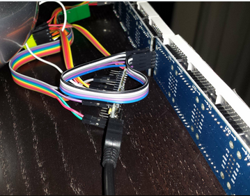
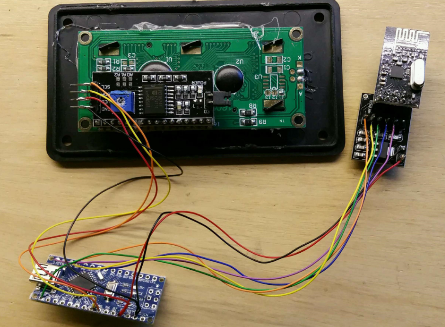
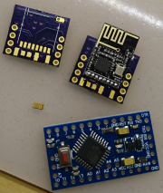
The yellow part is a smd tantalum 4.7uF capacitor. I had the smd nRF24l01 already soldered on the board (takes a little exercise).

      Soldered with pin headers. The author soldered it "trough-hole" without headers.
      0_1487515869578_upload-4626267c-7169-4475-9aa7-e11e40db09190_1487516051581_upload-0e1db919-3304-4dc2-881b-9c0c2e3b9bdf 
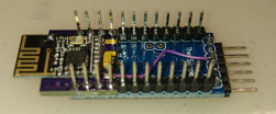
You need wires from the board to Vcc and Gnd.

      Comparison with jModule:
      0_1487515950101_upload-9d222b3f-c342-426e-9e08-8fda9201a10e 0_1487515980034_upload-c1a4776d-8746-4b15-9324-3df09369f6dd

      Ready for 4 new MySensors projects 🙂
      0_1487516135469_upload-baffb796-a7dc-436b-a138-5f6d2d0ca9e3

      posted in My Project
      AWI
      AWI
    • RE: The examples on the website need love

      Sounds like a succes story. A few remarks...

      • I started in a similar way and soon find out it is and should be a learning experience.

      • plug and play is not very satisfying. A good amount of trial and error is the learning experience. "wasting a sunday on MySensors" is a contradiction in my view.

      • examples are just a good start and function most of the time. The community need to take care of maintaining them. As I read you already did a good job here ☝

      • MySensors is typically a low power sensor thingy. Using sleep() is very useful for most sensors (nor actuators)

      • I hope you got infected and help building a great learning experience for beginners and more advanced users.

      posted in General Discussion
      AWI
      AWI
    • Power/ Usage sensor - multi channel - local display

      It is a power meter device which displays: current power, daily usage and total usage of upto 12 S0 meters and sends all the information through the MySensors network. The current sketch displays power used and generated from the different channels and uses a rotary encoder to browse the displays and adjust the (total values).upload-47e80693-5e06-4b90-9e6b-c435212fc038 
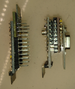
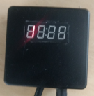
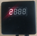
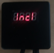
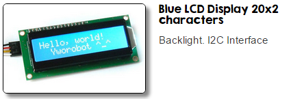
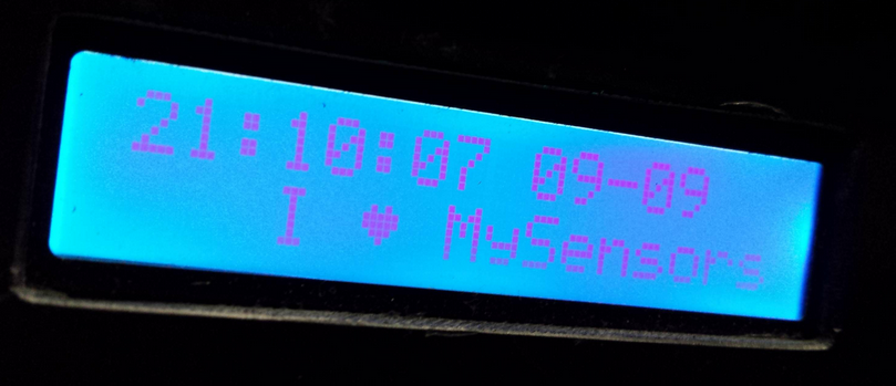
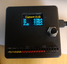
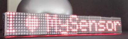
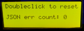
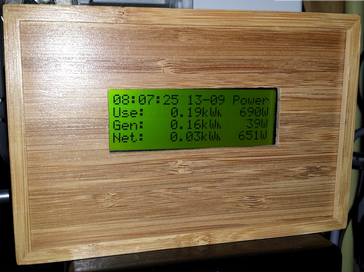
(also added message communication to the display from the controller (V_TEXT).
      With reference to my earlier project I reworked the whole thing to be more reliable and added functionality. The basic concept is the same:

      1 Arduino doing the time critical measurement and counting of the pulses and time, sending the measurements via a one-wire serial in JSON
      upload-e7fcad43-2ae0-4762-8c25-7d1bc3c71e2b
      including "patch panel" for connection to the S0 meters.
      upload-d07ff26c-a941-4923-9324-7b7842627af2

      Another arduino reading the JSON string and performing the tasks like display and sending the values over the MySensors network.
      upload-bbac86e4-758d-4794-8740-05e22b54be8d
      The grey and white wire connect to the "measurement" Arduino.

      some displays:
      upload-762b5e1e-dada-4314-ae95-7d6fa6c1b2aa
      adjusting the values

      upload-b1afc999-309b-4b5a-9170-c4998e2c7627
      reset the daily values

      posted in My Project
      AWI
      AWI
    • Request for contribution - controller selection matrix

      Following up on a the need for guidance in several posts by @stefaanv , by @samppa we started a simple Controller selection matrix.
      The purpose of the matrix is to compare the different controllers on MySensors specific features (not on the generic ones) to get global idea on which controller to choose (or test) for your MySensors network.
      Contribution to this tool is very much appreciated, so if you know the peculiarities of one or more controllers please help us filling the matrix or make comments on this post.

      The sheet includes a small selection of popular controllers, let's make it complete!

      The (editable) Controller Selection Matrix

      The list of controllers bold is (partly) filled by a few volunteers, are you the next one?:

      Ago Control
      Calaos
      Domoticz
      DomotiGa
      FHEM
      Freedomotic
      Home Assistant
      Homeseer
      Homey
      HoMIDoM
      Indigo Domotics
      ioBroker
      Jeedom
      MajorDoMo
      MyController.org
      MyNodes.NET
      Node Red
      OpenHAB
      openLuup
      PiDome
      pimatic
      Vera

      posted in Controllers
      AWI
      AWI
    • Slim Node scene controller/ keypad

      Inspired by the Battery button sensor, a look at "how low can you go"

      0_1455376405391_upload-51c797dd-68ab-4248-b99c-860b1c4c704b

      Not much more than a standard 16 key touchpad and the ever popular slim node.

      Have it sleep on interrupt only (no timer delay)

      DVint = sleep(DV_int, FALLING, 0);  // sleep, node wakes up on key interrupt  (sleep returns int number)
      

      and it will last for years on a coin cell. i.e.
      250mAh battery ; 50 keypresses a day ; results in > 7 year battery life!

      Now thinking on which housing to use.. I wish I had the skills for something like this 😞 . 0_1455377221330_upload-934ee488-5c34-466a-8224-f9c3b8eef5d5

      posted in My Project
      AWI
      AWI
    • RE: Slim Node scene controller/ keypad

      Completed the design... not a beauty but functional. Expected lifetime with the battery > 50 yrs (2.2 uA, completely theoretical. Batteries aren't of that quality )

      0_1455566548551_upload-2e761d10-068c-47f0-b8a3-69293e0f16af 0_1455566654262_upload-7d7d7ec0-bf07-4d2e-a154-ef803959bfd3 0_1455566600056_upload-7136a779-06eb-4a1e-b6d9-c092af1fa87e
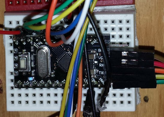
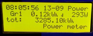
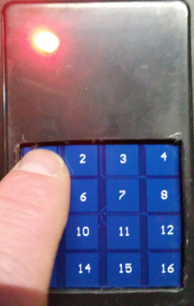
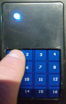
. The bi-color LED was added to show the on/off state when toggling a scene. (and because @GertSanders likes flashing led's 😀 )

      posted in My Project
      AWI
      AWI
    • RFID Card reader - Wiegand

      An universal RFID reader using the Wiegand protocol.
      0_1478440526897_upload-fed74ddb-acd8-40b9-8431-c4e2ffd93fdd

      a few features:

      • Can add/ delete/ list rfid codes (with hardcoded master rfid tag)
      • 4 digit 7 segment display
      • Store rfid codes in EEPROM (AVR) (be aware - limited room available)
      • Reports status log to MySensors controller
      • Stores Rfid tags in local memory and presents them as switches to the controller
        ○ Switch on - enable / switch off - disable
      • Communicates via RS485 for security (not necessarily)

      A nice commercial waterproof sealed wiegand rfid reader with buzzer and led can be found for a few bucks. The Wiegand protocol is a well established standard for card reader communication and can be interfaced easily with an Arduino. The interface of this type uses 5V logic but the reader needs 9-12V to function.
      0_1478440971635_upload-1c0ad37e-9999-4453-b720-94bd31802d55 
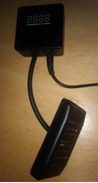
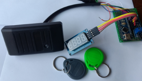
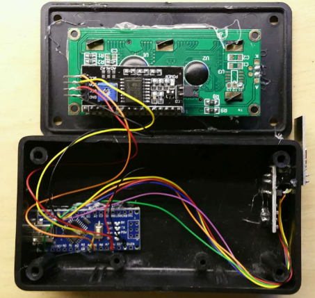
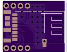
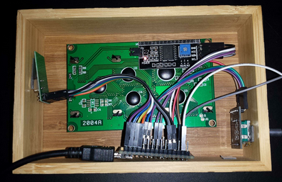
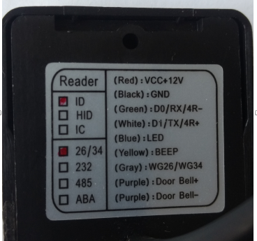
The back side shows the wiring: Wiegand wires are D0 and D1. I also use the LED and BEEP to get some feedback to the user. (the WG26/WG34 can be used to switch between 26 and 34 bit protocol, the "door bell" wires are not even there 😕 )

      A few pictures of hardware. All pretty straightforward connections.
      0_1478441720110_upload-afbf23c8-c964-42b4-864a-7be340b94e7a

      There is a 7-segment display which has a simple interface and a lot of functionality.
      0_1478441768013_upload-e1bd62ba-bb00-42c7-b1b9-2844818a0d7a
      Connected to a RS485 test setup.

      0_1478441948792_upload-15b743bf-7835-4995-a286-ec0a0568f9de 0_1478441975194_upload-c63fd66a-0f41-4a8c-a838-31180d047a92 0_1478442059886_upload-86ede3d5-0303-40bf-b9c4-2cba19295c26 0_1478442105543_upload-cdbcead9-07aa-4359-b246-bc1836a29098 0_1478442141295_upload-a817f39a-64ce-4114-b517-16486ea6ed4d
      And the display showing the presented rfid tag 1 & 2, inclusion mode, deletion mode and error.

      The whole project was meant to play with a FiniteStateMachine machine library/ class, which worked out well (for me 😏 ). This class lets you define "states" for which you create entry, update and exit functions. Worth a try... You can find the sketch and libraries on git. All libraries used are put in the sketch folder.

      more reading in the main sketch

      /*
       PROJECT: MySensors / Wiegand card reader with display
       PROGRAMMER: AWI
       DATE: 20160920 last update: 20161020
       FILE: AWI_Cardreader.ino
       LICENSE: Public domain
      
       Hardware: ATMega328p board w/ RS485
      	and MySensors 2.0 
      		
      Special:
      	
      Summary:
      	Wiegand reader - universal card reader
      	4 7-segment display
      	RS485 interface with MySensors (wired for security, cardID's are sent to controller)
      	
      	1. A local database with Card id's is kept in the node. Card id 0 is the "master master" card. With the master card you can:
      	- Open the door lock (just present it)
      	- Include other cards (present it twice and present the new card)
      	- Delete cards (present it three times, present the card to be deleted and confirm with master card)
      	- Browse the cards (present it four times), the display shows the card indexes with their status.
      
      	2. Any registered card opens the lock for a short time. A non registered card shows "Err"
      	
      	3. A new (included) card is presented to the controller as a switch with "On" status and a node-id which is the same as the card index. The CardID is added as text
      	
      	4. A card deletion will set the corresponding switch to off (to be implemented = switching a card to off in the controller will delete the card)
      	
      	5. The card "browse" function will (re)"present" all the activated cards (again) to the controller
      	
      	
      Remarks:
      	Fixed node-id
      	State machine based on FiniteStateMachine library
      	
      Change log:
      20160920 - created
      20161020 - updated to include MySensors V_TEXT status log. Log should be kept by controller
      20161023 - clean & comment code
      */
      #define MY_NODE_ID 10
      #define NODE_TXT "Cardreader 10"					// Text to add to sensor name
      //#define MY_PARENT_NODE_ID 3						// fixed parent to controller when 0 (else comment out = AUTO)
      #define MY_DEBUG 									// Enable MySensors debug to serial
      #define MY_PARENT_NODE_ID 0							// define if fixed parent
      #define MY_PARENT_NODE_IS_STATIC
      #undef MY_REGISTRATION_FEATURE						// sketch moves on if no registration
      #define MY_TRANSPORT_DONT_CARE_MODE					// transport connection to Gateway not essential/ needs to work without
      
      // Enable RS485 transport layer
      #define MY_RS485
      #define MY_RS485_DE_PIN 4							// Enables DE-pin management 
      #define MY_RS485_BAUD_RATE 19200					// Set RS485 baud rate (max determined by AltsoftSerial)
      // or use radio:
      //#define MY_RADIO_NRF24							// Enable and select radio type attached
      //#define MY_BAUD_RATE 9600
      
      #include <SPI.h>
      #include <MySensors.h>
      
      #include "CardDB.h"									// AWI: local lib to store cards
      #include "Wiegand.h"								// Wiegand protocol lib https://github.com/monkeyboard/Wiegand-Protocol-Library-for-Arduino
      #include "FiniteStateMachine.h"						// FiniteStateMachine https://github.com/gusgonnet/particle-fsm/tree/master/firmware
      #include "LedFlash.h"								// AWI: non blocking class for flexible LED/ buzzer 
      #include "SevenSegmentTM1637.h"						// 4 digit 7 segment display https://github.com/bremme/arduino-tm1637
      
      // helpers
      #define LOCAL_DEBUG
      #ifdef LOCAL_DEBUG
      	#define Sprint(...) (Serial.print( __VA_ARGS__))				// macro's as substitute for print,println 
      	#define Sprintln(...) (Serial.println( __VA_ARGS__))
      #else
      	#define Sprint(...)
      	#define Sprintln(...)
      #endif
      //** door lock 
      const byte DOORLOCK = 5 ;
      //** LedFlash lib used for the Buzzer and Led on the cardreader */
      const byte LED_PIN = 6;												// status led
      const byte BEEP_PIN = 7 ; 											// beep
      //** LED Display connections (library serial protocol)
      const byte PIN_CLK = A4;   											// define CLK pin (any digital pin)
      const byte PIN_DIO = A5;   											// define DIO pin (any digital pin)
      //** MySensors children
      const byte CARD_CHILD = 0 ; 										// MySensors master card child (rest of cards are dynamic)
      const byte CARD_ID_CHILD = 1 ; 										// MySensors card id/ log sensor 
      
      const unsigned long MASTERCARD = xxxxxx ;							// Hardcoded MASTERCARD, insert your master card number
      
      // Instantiate library objects
      SevenSegmentTM1637    display(PIN_CLK, PIN_DIO);					// LED display
      LedFlash statusLed(LED_PIN,true, 50, 400);							// status led (active on, flash on 50ms/ period 400ms )
      LedFlash statusBeep(BEEP_PIN,true, 2, 400);							// buzzer (active on, flash on 2ms/ period 400ms )
      CardDB cardDB ; 													// EEPROM database routines
      WIEGAND wg;															// instantiate Wiegand
      
      // state machine definitions (&routines need to be defined)
      FState idleState( &idleEnter, &idleUpdate, NULL );  				// Idle state (doe not need exit routine)
      FState delayState( &delayEnter, &delayUpdate, &delayExit);	  		// delay after invalid card
      FState unlockState( &unlockEnter, &unlockUpdate, &unlockExit);  	// Unlocks after valid card
      FState includeState( &includeEnter, &includeUpdate, &includeExit);  // waiting for inclusion of new card
      FState deleteState( &deleteEnter, &deleteUpdate, &deleteExit);  	// deletion of card
      FState confirmState( &confirmEnter, &confirmUpdate, &confirmExit);  // confirmation of deletion
      FState browseState( &browseEnter, &browseUpdate, &browseExit);  	// browse cards
      FiniteStateMachine stateMachine(idleState) ; 						//initialize state machine, start in state: noop
      
      const unsigned long idleTime = 2000UL ;								// delay to return to idle
      unsigned long browseTimer = millis() ;								// timer for browsing
      const unsigned long browseTime = 800UL ;							// detay for browsing
      
      unsigned long heartbeat = 60000UL ;									// heartbeat every hour
      unsigned long lastHeartbeat = millis() ; 
      
      unsigned long lastUpdate = millis(); 								// timer value
      
      
      unsigned long lastCardID = 0 ;										// holds last card value for inclusion / deletion
      int curCard = 0 ;													// Used as a browse pointer and temp store for deletion/ inclusion
      bool newCard = false ;												// global to indicate new card is available
      
      // MySensor messages
      MyMessage cardStatusMsg(0,V_STATUS);								// Each card id has its own "Switch", which is presented at inclusion
      MyMessage cardIdMsg(0,V_TEXT);										// Each card id has its own identifier, sent a text to controller 
      
      
      void setup() {
      	pinMode(DOORLOCK, OUTPUT) ;										// doorlock connection
      	display.begin();												// initializes the display
      	display.setBacklight(10);										// set the brightness to x %
      	display.print("INIT");											// display INIT on the display
      	wait(1000) ;
      	wg.begin();														// activate wiegand
      	lastUpdate = millis() ;
      	cardDB.initDB();												// ONLY in the first run to clear the EEPROM store (comment later)
      	cardDB.writeCardIdx(0, MASTERCARD);								// MASTER card (HARD CODED)
      	cardDB.setCardTypeIdx(0, CardDB::masterCard) ;					// write to 0 index in database
      	Sprint("EEPROM: ");
      	Sprintln(EEPROM_LOCAL_CONFIG_ADDRESS, HEX) ;
      }
      
      void presentation(){
      	sendSketchInfo("AWI " NODE_TXT, "1.2");							// Sketch version to gateway and Controller
      	presentCard(CARD_CHILD) ;										// present the master card (index == 0)
      	present(CARD_ID_CHILD, S_INFO, "SwitchID " NODE_TXT);			// present the log child
      }
      
      void loop() {
          unsigned long now = millis();									// timer value for "once in a while" events
          if (now-lastUpdate > 5000UL) {									// change after 5 seconds
      		//cardDB.printDB() ;										// only for debug
      		lastUpdate = now;
      	}
      	newCard = wg.available() ;
      	if(newCard){
      		Sprint("Wiegand HEX = ");
      		Sprint(wg.getCode(),HEX);
      		Sprint(", DECIMAL = ");
      		Sprint(wg.getCode());
      		Sprint(", Type W ");
      		Sprintln(wg.getWiegandType());
      		//sendLog(wg.getCode(), "presented");
      	}
      	stateMachine.update();											// check and update non blocking
      	statusLed.update() ;
      	statusBeep.update() ;
      	}
      
      	
      /* 	State machine
      **	Each state can have functions for enter/ update / exit (defined earlier)
      */
      
      //** ILDE tate **//
      void idleEnter() {Sprintln(" idle enter") ;
      	statusLed.off() ;
      	statusBeep.off() ;
      	display.clear();													// emptdisplay
      }
      void idleUpdate(){
      	if (newCard){
      		curCard = cardDB.readCard(wg.getCode()) ;						
      		if(curCard != cardDB.maxCards){									// card found
      			if(cardDB.readCardTypeIdx(curCard) == CardDB::masterCard || cardDB.readCardTypeIdx(curCard) == CardDB::idCard) { // only open if id or master card
      				stateMachine.transitionTo(unlockState);
      			} else if (cardDB.readCardTypeIdx(curCard) == CardDB::delCard){// card found but deleted
      				display.print("Errd");
      				sendLog(wg.getCode(), "Deleted Card");
      				stateMachine.transitionTo(delayState);
      			}
       		} else {														// card not found
      			display.print("Err");
      			sendLog(wg.getCode(), "Unknown Card");
      			stateMachine.transitionTo(delayState);
      		}
      	}
      }
      
      //** DELAY state **//
      void delayEnter() {	Sprintln(" delay enter") ;
      }
      void delayUpdate() {
      	if (stateMachine.timeInCurrentState() > idleTime){
      		Sprintln(" to idle") ; stateMachine.transitionTo(idleState);
      	}
      }
      void delayExit(){Sprintln(" delay exit") ;}
      
      //** UNLOCK state **//
      void unlockEnter() {Sprintln(" unlock enter") ;
      	display.print(curCard);												// display Card index (curCard) on the display
      	Sprintln("Door unlocked");
      	sendLog(wg.getCode(), "Unlocked");
      	lockDoor(false) ; 													// Unlock the door
      	send(cardStatusMsg.setSensor(curCard).set(1));						// send update for sensor (card) to show its usage.
      }
      void unlockUpdate() {
      	if (stateMachine.timeInCurrentState() > idleTime){
      		Sprintln(" to idle") ;
      		stateMachine.transitionTo(idleState);
      		}
      	if (newCard){														// new tag
      		if(cardDB.readCardType(wg.getCode()) == CardDB::masterCard){	// master card, prepare for inclusion
      			Sprintln(" to include") ;
      			stateMachine.transitionTo(includeState);
      		}
      	}
      }
      void unlockExit(){Sprintln(" unlock exit") ;
      	lockDoor(true) ; 													// Lock the door
      	Sprintln("Door locked");
      }
      
      //** INCLUDE state
      void includeEnter() {
      	Sprintln(" include enter") ;
      	display.print("Incl");
      	statusLed.flash() ;
      	statusBeep.flash() ;
      };
      void includeUpdate(){
      	if (stateMachine.timeInCurrentState() > idleTime){
      		Sprintln(" to idle") ;
      		stateMachine.transitionTo(idleState);
      	}
      	if (newCard){														// new tag
      		curCard = cardDB.readCard(wg.getCode()) ;
      		if (curCard != cardDB.maxCards){								// known card
      			if(cardDB.readCardTypeIdx(curCard) == CardDB::masterCard){	//  master card, goto delete state
      				Sprintln(" to delete") ;
      				stateMachine.transitionTo(deleteState);
      			} else {													// known other card, so only change card type
      				cardDB.setCardTypeIdx(curCard, CardDB::idCard) ;					
      				display.clear(); display.print(curCard);
      				sendLog(wg.getCode(), "re-included");
      				presentCard(curCard); 									// present the new card as a switch and switch on
      				Sprintln(" to delay") ; stateMachine.transitionTo(delayState); // delay only to extend display time
      			}
      		} else {														// unknown card, so add in empty spot
      			curCard = cardDB.writeCard(wg.getCode()) ;
      			if(curCard == cardDB.maxCards){								//  if maxCards, database full
      				display.clear(); display.print("Full") ;
      				sendLog(wg.getCode(), "DB full");
      				Sprintln(" to delay") ; stateMachine.transitionTo(delayState); // delay only to extend display time
      			} else {													// include 
      				display.clear(); display.print(curCard);
      				sendLog(wg.getCode(), "included");
      				presentCard(curCard); 									// present the new card as a switch and switch on
      				Sprintln(" to delay") ; stateMachine.transitionTo(delayState); // delay only to extend display time
      			}
      		}
      	}
      }
      void includeExit(){
      	Sprintln(" include exit") ;
      	statusLed.off() ;
      	statusBeep.off() ;
      	}
      
      //** DELETE state
      void deleteEnter() {
      	Sprintln(" delete enter") ;
      	display.print("Del");
      	statusLed.flash() ;
      	statusBeep.flash() ;
      };
      void deleteUpdate(){
      	if (stateMachine.timeInCurrentState() > idleTime){
      		Sprintln(" to idle") ; stateMachine.transitionTo(idleState);
      	}
      	if (newCard) {
      		if(cardDB.readCardType(wg.getCode()) == CardDB::masterCard){	//  master card, goto Browse
      			Sprintln(" to browse") ;
      			stateMachine.transitionTo(browseState);
      		}else {	
      			lastCardID = wg.getCode() ;									// store code for deletion
      			Sprintln(" to Confirm") ; stateMachine.transitionTo(confirmState);
      		}
      	}
      }
      void deleteExit() {	Sprintln(" delete exit") ;}
      
      //** CONFIRM state
      void confirmEnter() { Sprintln(" confirm enter") ;
      	display.print("Conf");
      	statusLed.flash() ;
      	statusBeep.flash() ;
      }
      void confirmUpdate(){
      	if (stateMachine.timeInCurrentState() > idleTime){
      		Sprintln(" to idle") ;
      		stateMachine.transitionTo(idleState);
      	}
      	if (newCard) {
      		if(cardDB.readCardType(wg.getCode()) == CardDB::masterCard){	//  master card means confirmed
      			Sprint("Delete Card: "); Sprintln(lastCardID) ;
      			cardDB.deleteCard(lastCardID);								// delete card (lib takes care of presence)
      			sendLog(wg.getCode(), "deleted");
      			send(cardStatusMsg.setSensor(lastCardID).set(0));			// switch controller status to "off"
      			Sprintln(" to idle") ; stateMachine.transitionTo(idleState);
      		}
      	}
      }
      void confirmExit() {Sprintln(" confirm exit") ;}
      
      //** BROWSE state
      void browseEnter() {Sprintln(" browse enter") ;
      	display.print("Brws");
      	curCard = 0 ;
      	browseTimer = millis() ;
      	statusLed.off() ;
      	statusBeep.off() ;
      
      }
      void browseUpdate(){
      	unsigned long now = millis() ;
      	if (newCard) {
      		if(cardDB.readCardType(wg.getCode()) == CardDB::masterCard){	//  master card, return to IDLE
      			Sprintln(" to idle") ; stateMachine.transitionTo(idleState);
      		}
      	}
      	if (now >= browseTimer + browseTime){
      		Sprint(" browse id: ") ; Sprintln(curCard);
      		browseTimer = now ;
      		display.clear();
      		display.print(curCard);
      		display.setCursor(0,2) ;
      		if(cardDB.readCardTypeIdx(curCard)== CardDB::masterCard){ 
      			display.print("ma");
      			presentCard(curCard); 									// present the cards again when browsing (to sync controller)
      		} else if(cardDB.readCardTypeIdx(curCard)== CardDB::idCard){ 
      			display.print("id");
      			presentCard(curCard);
      		} else if(cardDB.readCardTypeIdx(curCard)== CardDB::delCard){ 
      			display.print("dl");
      			presentCard(curCard);
      		} else if(cardDB.readCardTypeIdx(curCard)== CardDB::noCard){ display.print("no");}
      		if (++curCard > cardDB.maxCards){								// idle if end of database
      			Sprintln(" to idle") ; stateMachine.transitionTo(idleState);
      		}
      	}
      }
      void browseExit(){Sprintln(" browse exit") ;}
      //** end of stae machine **//
      
      // lock / unlock the door
      void lockDoor(bool doorState){
      	digitalWrite(DOORLOCK, doorState?HIGH:LOW) ;						// Adapt for active low of any other door unlock
      }
      
      // sends a log message to the controller containing a message and cardID
      void sendLog(unsigned long cardID, const char logMessage[]){
      	char tmpBuf[26] ;													// temporary store for message
      	sprintf(tmpBuf, "Card %8lu %-10s", cardID, logMessage);				// sends unsigned long and message (be aware of message length)
      	Sprintln(tmpBuf) ;
      	send(cardIdMsg.setSensor(CARD_ID_CHILD).set(tmpBuf));
      }
      
      // present a (new) card to the controller by presenting it and switch it to state (master, id = On, deleted = Off)
      void presentCard(byte cardIdx){
      	char tmpBuf[26] ;													// temporary store for message
      	sprintf(tmpBuf, "CardId %8lu", cardDB.readCardIdIdx(cardIdx));		// convert the cardID to text
      	Sprintln(tmpBuf) ;
      	present(cardIdx, S_BINARY, tmpBuf) ;								// present the (new) card (idx == child) to controller
      	wait(50) ;															// give it some time to settle
      	send(cardStatusMsg.setSensor(cardIdx).set(cardDB.readCardTypeIdx(cardIdx)==CardDB::delCard?0:1)); // switch according to type
      }
      
      // Handle incoming messages, remote card i.e. disable/ enable
      void receive(const MyMessage &message) {  								// Expect few types of messages from controller
      	if (message.type == V_STATUS){										// Switch "off" messages are handled as deletions
      		if (message.sensor < cardDB.maxCards && message.sensor > 0){	// take care of non existing sensors and master
      			cardDB.setCardTypeIdx( message.sensor, message.getBool()?CardDB::idCard:CardDB::delCard) ;	// set type according to payload
      		}
      	}
      }
      
      posted in My Project
      AWI
      AWI
    • Amazing progress...

      I have been away/ ill for only a few months and slowly returning to the forum... I almost feel like a stranger 😉

      and so much progress:

      • missed a great gathering in the Netherlands 😞
      • recreated web site! (I have to find my way again) 👌 @hek
      • a whole new core (nothing but progress, and some learning to do) 💕 @tekka & core team
      • unbelievable community support. (👍 @mfalkvidd, @sundberg84 and many (new) others)
      • mysensors workshops (👏 @TheoL )
      • etc.
      posted in General Discussion
      AWI
      AWI
    • LCD Clock and Text sensor node with new V_TEXT

      With good cooperation of @hek and @GizMoCuz (Domoticz) a TEXT sensor is introduced. It is currently in development stage but I hope will make it to production soon. The V_TEXT variable makes simple text message transfer possible intra-node and between node and controller.

      Below a first experiment. More to follow!

      "Sensor Node" My sensorboard (can be any board or just a nano with wires):
      upload-15e45402-6839-4ff9-a32d-9fabbd1f3f35

      "LCD Display" (standard 2x16 char, I2C):
      upload-1fd2549d-5e44-4896-832b-ce642fc2e84c

      start the sketch (end of post). Activated sensor in Domoticz:
      upload-e588beb4-52a2-49ea-ad93-14fc634b99bf

      You can update the text in Domoticz with JSON (or many other ways). The last part is the text

      http://192.168.2.20:8080/json.htm?type=command&param=udevice&idx=369&nvalue=0&svalue=I %01 MySensors
      

      and on the LCD
      upload-e907075a-f500-46a2-9fbc-cebb2d3c4107

      I'm happy....

      If you like to experiment: get the development version of MySensors or just add the V_TEXT as described in the example sketch:

      /*
       PROJECT: MySensors / LCD display for text from controller
       PROGRAMMER: AWI
       DATE: september 8, 2015/ last update: september 8, 2015
       FILE: AWI_LCD_49.ino
       LICENSE: Public domain
      
       Hardware: tbd ..MYS Ceech - ATmega328p board w/ NRF24l01
      	and MySensors 1.5 ()
      		
      Special:
      	MySensors - Development (as of sept 2015)
      	
      SUMMARY:
      	display time & 2 lines of text from Controller Text sensors
      */
      
      
      #include <MySensor.h>          				// Mysensor network
      #include <SPI.h>
      #include <LiquidCrystal_I2C.h>
      #include <Time.h>   						//http://playground.arduino.cc/Code/Time
      #include <Wire.h>		         			
      
      // uncomment if you are using the DEVELOPMENT version with V_TEXT & V_INFO defined (better to use development MyMessage.h)
      //const byte V_TEXT = 47 ;					// values taken from development edition MyMessage.h
      //const byte S_INFO = 36 ;
      
      const byte nodeId = 49 ;					// MySensors fixed node id
      const byte LCD1_CHILD = 8 ;					// LCD line 1
      const byte LCD2_CHILD = 9 ;					// LCD line 2
      
      char lastLCD1[21] = "Line1 - first   ";		// define & init before first receive
      char lastLCD2[21] = "Line2 - second  ";
      
      boolean timeReceived = false ;
      // timers for loop delays
      unsigned long lastUpdate=0, lastRequest=0, lastDisplay=0;
      int display_no = 0 ; 						// current display
      
      // *** Definition and initialisation
      // define the MySensor network
      MyTransportNRF24 transport(9,10); 			// Sensoduino (8,7) Ceech board, 3.3v (7,8)  (pin default 9,10)
      MySensor gw(transport);  
      
      // Initialize messages for sensor network
      MyMessage textMsg(0, V_TEXT);
      //                    addr, en,rw,rs,d4,d5,d6,d7,bl,blpol
      LiquidCrystal_I2C lcd(0x27, 2, 1, 0, 4, 5, 6, 7, 3, POSITIVE);  // Set the LCD I2C address
      
      // OPTIONAL: Custom characters for display - Units)
      byte heart[8] = { B00000, B01010, B11111, B11111, B01110, B00100, B00000, B00000};
      
      void setup(void){
          //Serial in Sensor network = 115200
          gw.begin(incomingMessage, nodeId); 					// this node is 49 fixed 
          //Send the sensor node sketch version information to the gateway
          gw.sendSketchInfo("AWI_LCD text 49", "1.1");
       	gw.present(LCD1_CHILD, S_INFO, "LCD line1");		// new S_type 20150905 (not know by domoticz)
          gw.present(LCD2_CHILD, S_INFO, "LCD_line2");
      	gw.send(textMsg.setSensor(LCD1_CHILD).set("-"));	// initialize the V_TEXT at controller for sensor to none (trick for Domoticz)
      	gw.send(textMsg.setSensor(LCD2_CHILD).set("-"));		
      
      	// Initializations
          gw.requestTime(receiveTime);						// get the time from controller (handled by receiveTime)
          
          // ** LCD display **
      	Wire.begin();										// I2C
          lcd.begin(16, 2);							    	// LCD 2 lines * 16 char.
          lcd.setBacklight(HIGH);
          lcd.setCursor(0, 0);
      	lcd.createChar(1, heart);
      
          // lcd.write(byte(0)); // write units
      }
      
      void loop(void){
          // timer for loop delays
          unsigned long now = millis();
          gw.process() ;
          // If no time has been received yet, request it every 10 second from controller
          // When time has been received, request update every hour
      	if ((!timeReceived && (now-lastRequest > 10*1000)) ||	
      		(now-lastRequest > 3600000UL)){					// request update every hour to keep in sync
             // Request time from controller. 
             Serial.println("requesting time");
             timeReceived = false;
             gw.requestTime(receiveTime);  
             lastRequest = now;
      		}
          // Change display and update sensors every 5 seconds
          if (now-lastDisplay > 5000){
      		lastDisplay = now;
      		gw.request(LCD1_CHILD, V_TEXT, 0); 					// request new values from controller
      		gw.request(LCD2_CHILD, V_TEXT, 0); 					// request new values from controller
      		// change display 
      		display_no++;
      			if (display_no >= 2){ // wrap for number of different displays for second line
      			display_no = 0;
      			}
      		}
          // Update display every second
          if (now-lastUpdate > 1000) {
      		LCD_local_display();
      		lastUpdate = now;
      		}
      	}
      
      // This is called when a new time value was received
      void receiveTime(unsigned long controllerTime) {
          Serial.print("Time value received: ");
          Serial.println(controllerTime);
          setTime(controllerTime); 							// time from controller
          timeReceived = true;
      	}
      
      // This is called when a message is received 
      void incomingMessage(const MyMessage &message) {
      	if (message.type==V_TEXT) {							// Text messages only
           // Write some debug info
           Serial.print("Message: "); Serial.print(message.sensor); Serial.print(", Message: "); Serial.println(message.getString());
      	if (message.sensor == LCD1_CHILD ) {
      		snprintf(lastLCD1, sizeof(lastLCD1), "%16s", message.getString());	// load text into LCD string
      		}
      	else if (message.sensor == LCD2_CHILD){
      		snprintf(lastLCD2, sizeof(lastLCD2), "%16s", message.getString());
      		}
      	} 
      }
      
      void LCD_local_display(void){
      // take car of LCD display information
          char buf[17]; // temp buffer for max 16 char display
          // start with location & time on first line
          snprintf(buf, sizeof buf, "%02d:%02d:%02d %02d-%02d", hour(), minute(), second(), day(), month());
          lcd.setCursor(0, 0);
          lcd.print(buf);
          lcd.setCursor(0, 1);
          if (display_no == 0){
            lcd.print(lastLCD1); 							// second line is text value from controller
          } else { 										// display == 2
            lcd.print(lastLCD2);
          }
      }
      
      posted in My Project
      AWI
      AWI
    • RE: How does mysensors relate to MQTT?

      @NeverDie said:

      can someone sum it up concisely in a couple of sentences

      I love to take that challenge 😉

      1. Instead of entering a highly sophisticated technical discussion. MySensors is just plain fun. Giving everybody the opportunity to (re)enter a world of mixed hard and soft(firm)ware. A hobby supported by a large network of enthousiasts.
      2. My daughter calls it "a nerd forum" which is a philosophy on itself
      3. (the technical side) MySensors heart is a communication protocol targeted to exchanging standard Sensor information, In that respect is cannot be compared to MQTT as it is a different (higher) application layer (OSI terms). MQTT is an IoT protocol for exchanging messages in a standard way (i.s.o standard messages)
      4. The MySensors protocol can be used on top of MQTT so nothing gets in the way...
      posted in General Discussion
      AWI
      AWI
    • RE: My Slim 2AA Battery Node

      @m26872 I have assembled 6 boards now and am very happy with the design. I use strips as a socket for the Atmega. This leaves enough room for components under it. Also made one with SPI connector. Works perfect! Thank you for sharing the design and instructions.upload-422d1df5-f52b-46fd-b28c-67493daa9fdc upload-aea4bc1e-e16a-4881-a378-e609a6c2f0c8

      posted in My Project
      AWI
      AWI
    • Very narrow and minimal switch node - low power consumption experiment

      The minimalistic Very narrow and minimal switch node lends itself for some battery experiments. A how low can you go study with a standard MySensors node.

      0_1457722773499_upload-28fac2fe-7b37-46d3-85e9-67e27e07c459

      The objective was to explore how long it can operate with a small i.e. CR1620 (3V, 75mAh, until 2V) battery.
      0_1457722630748_upload-35c9f36d-b595-4192-bc6b-8c34957360b2

      The node is attached to a 'reed contact' magnetic sensor.
      0_1457722693924_upload-25b14c9d-2d32-4500-9d3c-9fa1af20a253 This one is connected between arduino pin D2 (connector) and GND.

      The node is programmed with the bootloader as described by @m26872 for the My slim battery node.

      The findings:
      ❗ Summary: minimum of 4 years operation ⭐

      Basic setup.. a uCurrent current to voltage converter. This one is set to 1mV per nA ! (0.001uA) The photo below shows the sleep current at ~3.00V supply voltage (nominal battery voltage (ignore the minus sign on the voltmeter. ;-))). Supply current during sleep ~0.9 uA!
      0_1457723198918_upload-4e7ac4b3-037e-4405-9a61-4e40922d33d9

      Dropping to ~0.5uA for a supply voltage of ~2.2V
      0_1457723546818_upload-ca10f390-906f-4842-aa9b-d48946a3a4dd

      The current during wake is ~13mA during ~4ms. This is for reading two magnetic door contacts and the battery voltage.
      0_1457723897902_upload-17ad5c32-d3a6-4005-b56e-308f75dbad0c

      A simple and conservative calculation (using the Android Electrodroid battery calculator):
      Sleep: < 1uA
      Wake: 13mA during 4ms and awake once every hour
      Average consumption: 1.014uA,
      Battery: 75mAh
      ---> expected lifetime: ~74000 hours = ~8.4 years !
      For a wake-up around every minute this would still be over 4.5 years.

      A CR1620 (dimension 16mm x 2.0mm) with a (75 mAh) capacity would fit perfectly with the Very narrow node in a 16x16mm housing. I am off to build some MySensors keyfobs (remote controls) 😉

      posted in Hardware
      AWI
      AWI
    • Orientation sensor (and actuator)

      With the latest additions in sensor type e.g. the position/ GPS sensor there was still something missing. Orientation sensors are popular in e.g. flight control and mobile phones. For a proof of concept I ordered a MPU 9250 which consists of a Gyroscope/ Accelerometer/ Magnetometer (compass) and BMP280 - barometer/ temperature.

      This is an advanced device which makes it possible to determine the exact orientation/ movement and altitude.. Mounted to @GertSanders "Battery based atmega328p sensor" this makes a perfect "Orientation sensor" with a simple I2C interface.

      0_1458657298726_upload-24c3d464-6128-4e81-b3da-b26fd04f285e

      For the purpose of demonstration there is an actuator which is basically a pan/tilt servo construction pre-built with 2 servo's and a little plastic.
      0_1458657078723_upload-3dd64be6-f5e0-4899-9c5d-05587980f2f2

      Next (hard to find) thing was an Arduino library to read the sensor an create acceptable position readings. In flight terms these are named:

      Yaw - for the orientation in the vertical plane
      Pitch - orientation in the horizontal plane
      Roll - the position of the object (e.g. aircraft) around its own axis. (not used in the example)

      As there (currently) is no "Orientation type" for MySensors I have created my own type as a subset from the V_TEXT type.
      V_ORIENTATION = Yaw ; Pitch ; Roll

      A (working) library was found in the "Modern devices - motion plug" example.

      The video should give you an idea of the current setup and workings. All through the MySensors network. I will upload the details on Openhardware.io if I can get the hang of it.

      MySensors - Orientation sensor Demo

      posted in My Project
      AWI
      AWI
    • RE: Very narrow and minimal switch node - low power consumption experiment

      -- revisited ---

      I changed the bootloader to a 8mHz version. As the processor runs 8 times as fast the active period pulse width is now < 0.5 ms (earlier 3.8 ms) The sleep and active consumption have not changed. This would reduce the 'pulse' burden on the coin cell as attentively mentioned by @scalz.

      0_1457896553845_upload-49f13d13-d4ed-46aa-8576-a47e5f271d2e

      Something comparable to 'internal resistance' increases as the charge reduces. This will impact the available voltage for the node. I used a conservative figure for battery capacity (50mAh) and a load current of 0.8uA which will be less if battery voltage goes down.

      0_1457897897541_upload-dae13a0d-52ee-46c3-b470-425dd5a225a0
      0_1457898169100_upload-60cbec3f-4bb1-480a-a7a8-d5077d6b3f92

      Have three nodes ready for real life test with constant battery measurement. I hope to report just within five years from now 💤

      posted in Hardware
      AWI
      AWI
    • Weather/ wind display

      As promised in my posting "Weathercock" / weather comfort station a more techie version of a similar thing. It display the wind direction/ gust and history on a WS2812b 24 led ring. And as an extra shows the actual weather data on an LCD display. A local temp/hum sensor measures the inside comfort indicators.

      0_1464171485675_upload-7b774889-88d6-453d-a281-021fbb561d3d

      A pushbutton lets the display browse through all the weather data and weather sources (Controller or "node to node" with a long press).

      The ring shows:

      • Bright LED and opposite 2 "tail" LEDs - wind direction and current gust (in rainbow colors)
      • Blue LEDs - cardinal wind directions (N, W, S, E)
      • (now) Green LEDs - the wind gust history (rainbow colors) in all directions for the last hour.

      This functionality pushed the capability of the Atmega328 (and mine/ my patience) to its limits...But I would love to get some feedback on possible improvements (including aesthetics)

      And the back/ inside:
      0_1464171571527_upload-bf4daa60-d4ee-4d55-83cb-c39894b614c0
      A little messy semi breadboard setup with main components:

      • @GertSanders "does it all" AC/DC/Batteries capable atmega328p board
      • a 24 WS2812b led ring
      • 2*16 I2C LCD display
      • Si7021 or compatible Hum/ Temp sensor
      • push button
      • IKEA Picture frame where I coated the glass with dark foil.
      • a few cables

      Next to its moving "Weathercock" friend who didn't like its picture taken and showed his back :

      0_1464172640036_upload-9297b8b3-8710-47b1-9c48-256d6adb6429

      posted in My Project
      AWI
      AWI
    • RE: NRF24L01+PA+LNA power consumption

      To demonstrate what happens I made some measurements on the NRF24L01+PA+LNA power consumption. The nano in the setup runs a simple sketch which sends one value every 100ms and sleeps in between (RF24_PA_MAX).

      First is the setup with a standard nRF24L01+ (working clone 😉 ) The current meter measures the current in the power line of the radio (before the regulator to avoid side effects) and has an internal resistance of 3.4 Ohm. The measured current is a kind of random average sample and shows around 4 mA.

      0_1464463953266_upload-0a19ffdd-3807-4724-9fd1-c809b69bff96

      Now look at the waveform of the same current on the scope. I circled the radio send current. The level of pulse is around 70mV which translates to ~20mA (0.07 V/ 3.4 Ohm)
      0_1464464509368_upload-399190d7-d122-4ebe-b88b-a2b4352eb726

      Second is the setup with a the nRF24L01+PA+LNA(working clone 😉 )
      0_1464464861402_upload-ea2156f5-3315-47a3-9568-62d1aa6b7687

      and the waveform on the scope.. around 700mV translates to ~200mA (0.7V/ 3.4.Ohm) 10 times as much and no comparison to the (random average sample) reading on the current meter of ~22mA (a Fluke meter does not change this ;-))

      0_1464465244455_upload-12912f74-4dfb-467a-9ae9-c0990c26eb50

      posted in Troubleshooting
      AWI
      AWI
    • Radiator booster (heating)

      Winter is cold and energy consumption going up. Time to get out of my cave and start a new project ;-).
      Low temperature heating systems use special radiators which can be benficial also for other heating systems.
      With a few PC vents I built a radiator booster to increase yield of my existing radiators. Still in research stage but results are promising. There are a few commercial options but these are either sub-optimal, expensive and not MySensorized👎
      0_1486224457799_upload-32148448-19bf-4fa3-bc2b-9e5390a6cb29 0_1486224551817_upload-e0df9470-6973-4978-910b-e172fce78276 0_1486224672608_upload-e6901de8-736a-43dd-bf72-c228abbdd8b5

      The workbench example built around a compact MySensors node jModule three Dallas temp sensors and PWM circuitry. The whole thing lives in or under the radiator.
      0_1486223384333_upload-15ca957a-7c92-457e-b732-46a1ec6671a1

      0_1486223717517_upload-c5ba7173-eb26-459b-99b9-978284cad0bc

      Working principle:

      • Measure temperatures for water in/ out and environment.
      • Vents start spinning slowly as the "In" temperature reaches a threshold (30 Celcius for now)
      • Vent spinning increase in time for a few minutes and then slowly spin down until constant level.
      • Vents stop spinning when temperature falls below threshold.
      • etc.

      Extra options:

      • Manual mode, started automatically when (MySensors) controller takes over.
      • Fan speed control for tuning

      I am curious if anybody has some hands-on experience on how to best tune the system. And will publish details (sketch) if anyone is interested.

      0_1486224230174_upload-d2dbb63e-1cfc-4a7a-8e14-5c10b6e057090_1486224762708_upload-40a2fd75-5190-4c40-8b63-42160b059d8d

      posted in My Project
      AWI
      AWI
    • MySensors - HUE bridge

      A bridge between the (Philips) HUE bridge and the MySensors network. Have MySensors controlled by HUE and add MySensors lights to the HUE system

      0_1490027237626_upload-109b33b1-7859-4930-9d72-6c8eb00483dc
      A while ago a did a major investment 🙂 in a HUE (Philips) hub and some peripherals. This system works with Zigbee protocol and is not compatible with MySensors. I like the way HUE handles colors (xy space, hvs and color temp) and the dimmer switches which are "harvesting" the energy i.s.o. using a battery.
      0_1490027489967_upload-94a12edd-9c79-43e9-849a-ad5bd17123ca

      The API for the HUE system is made public available and is rather well documented. There are a few controllers which support the API but this is a fun project and exercise for working with the ESP8266 and color handling/ conversion.

      What is needed:

      • an ESP8266 board (NodeMCU / WeMos)
      • a HUE bridge (and possibly some lights/ switches)
      • a MySensor system and controller (best one which can connect multiple gateways)

      a few libaries:

      • ArduinoJson (for exchanging information with the Hue bridge)
      • FastLED (just because It is great 😉 and contains some many color manipulation routines)
      • The library and sketches in my Github - AWI_MySensors_HUE

      In the main sketch you need to change the IP's of your controller and Hue bridge and other settings for your Hue bridge.

      posted in My Project
      AWI
      AWI
    • RE: Sleep() with interrupt only works with level "LOW"

      @Yveaux Pigheaded as I am... (AVR made some more mistakes in their documentation) .. I got 12 different atmega328p processors from different sources on the test bench (custom, TQFP & DIL, pro-mini 3.3 /5V) and was not able to produce proof of : 0_1490897465883_upload-4a1e7b13-42e2-49bb-b132-1927b9dd669d.
      I got consistent behaviour with using CHANGE, RISING, FALLING and LOW using the SLEEP_FOREVER mode of the low power library.

      "RISING"
      0_1490898088157_upload-3fd4332e-59a0-466c-b5c5-6e33ec8ff117
      and similar for "CHANGE"
      0_1490898242474_upload-f8afe558-13bb-4fd4-a2d8-b6e512c70888
      So "the question": out of spec 😐 - or - invalid spec 😟

      posted in Bug Reports
      AWI
      AWI
    • RE: Your workshop :)

      Just cleaned...

      Street view
      0_1460821194607_upload-6de61b72-900f-465c-b9cf-405a0d16384b

      Multimeter fetish
      0_1460821122767_upload-1c908acd-cb9c-49a3-8241-f2468db3994a

      Storage for components of my Chinese (and European) friends. I order large amounts ..
      0_1460821335790_upload-1fe18fbf-2227-499c-a0c4-4e770b535071

      Built 35 years ago and still unbeatable..
      0_1460821493903_upload-5c853767-2361-4b8a-9095-24c2aa897f13

      My latest - a universal component tester 11 Euro... kudo's for the one that designed this
      0_1460821649219_upload-9d31fdf8-af6e-49d4-a092-534a19919dab

      posted in General Discussion
      AWI
      AWI
    • Solar - Temperature, Humidiy & Pressure board with charge monitoring

      I was not able to resist the new ceech board the and the lucky one to receive the fully populated samples last week.
      upload-89bab277-7397-4e7e-b141-69e1256d1b7d

      The board incorporates the hardware to solar charge a li-ion cell including the measurements for voltage & current of both solar and cell.

      To test the board I dismantled a cheap solar garden light and connected a CR123 li-ion cell.

      The result
      upload-72541f2f-580d-4917-8284-94e01151b879

      For testing purposed I found that it works well to connect a HC-05 bluetooth module and use a mobile phone with bluetooth terminal to read the serial port. This way I don't need to carry a PC around the house. You can see the board producing it's intelligence 😆

      upload-abb628e4-d756-40b3-8ac0-7552f5e3901d

      and the sketch which is communicating with the MySensors network

      https://codebender.cc/sketch:108650

      posted in My Project
      AWI
      AWI
    • RE: Witch temp/hum sensor is best to use for battery powered sensors?

      @Cliff-Karlsson use an i2C model BME280/Si7021/ SHT21/ HTU21. These work on low voltages and consume minimal. You can find boards with or without voltage regulator and/or pull-up's on Ali. Take a look at a great study which compares many of the sensors available.
      0_1462254372062_upload-79a354cb-d5fe-4348-a646-54119c97bd55

      posted in General Discussion
      AWI
      AWI
    • Slim CR123A (2AA) battery node..

      Have been playing with the "Slim 2AA battery node" and a small motion sensor. As most motion sensors are not comfortable with voltages under 3v, a CR123 rechargable 3.7V cell is used. This makes the design even smaller ;-).
      The "spider" breadboard:
      upload-c5f1e6a1-350b-4e1d-8fae-971c70e9a284

      The IR detector has an on-board regulator which is used to power the ATMEGA and radio.
      upload-b4a38d20-64c8-4a1a-9aa5-c85bcc41b5f9.

      Just need to wait a little longer for the housing.. I will post a picture when completed.
      upload-61673887-a5f2-4e07-a922-6e09989dc5e4

      The rechargeable battery mentions 2300mAh which is not realistic, but from experience it will keep the node alive for at least a year before a recharge is needed (outdoor use). Power consumption of the node is mainly from the motion sensor (~45uA) total 55 uA.
      upload-a2e8cb8f-0306-4910-83bb-0b5db560fe6f

      posted in My Project
      AWI
      AWI
    • RE: Nice cases/housings for projects

      @pansen If you like wood. You can start with ready made boxes. I used some dismantled Ikea DRAGON boxes (bamboo)
      0_1487189763563_upload-a2a6f386-564d-4513-8016-95ac11bc7d6e to house my projects..

      0_1487189918764_upload-77af7dac-f13d-4142-98b9-2687f589bbf8

      The picture frames can also be morphed into something usable 😉

      posted in Enclosures / 3D Printing
      AWI
      AWI
    • Weather station (the easy way)

      0_1480253341024_upload-ebb7461f-ab8e-40cc-9abc-ce5a8ec4dc8c
      0_1480254024024_upload-482a7846-9931-49b2-b759-ca6cb4acc1eb 0_1480254065284_upload-790552c6-0edd-4e04-a464-1b92be935007 0_1480254104379_upload-a591595a-6924-492f-b385-18eaf8c2af75

      I'm still strugling with my 'innovative' weather station. I will be using a acceleration sensor and 'almost' ready. Hope to finish it this winter. In the mean time... at the Weather Underground website. It seems there are a lot of 'neighbours' within a circle of a few hunderd meters who invested and enormous amount in equipment and... publishing the measurements together with professional weather stations.
      0_1480252617383_upload-626f0fe3-b0a5-4bb1-ba04-f82ff8d748fa

      After a few minutes of searching, I found the work of Daniel Eichorn who built an esp8266 weather station which I was able to tweak a little and MySensor'ise..
      The work of Daniel is documented well and the libraries can be installed from the Arduino IDE library manager.

      I changed the "Weather underground" library a little to get more information from WU and added the MySensors stuff to to main sketch. You can find both on my git.

      below a MyController screenshot of a few weather parameters.
      0_1480253453530_upload-f3c59d46-d960-4792-9d24-ad7db1928036

      These values are sent to the controller

      	send(msgTemp.setSensor(temperatureChild).set(wunderground.getCurrentTemp().toFloat(),1)) ;
      	send(msgTemp.setSensor(temperatureDewpointChild).set(wunderground.getDewPoint().toFloat(),1)) ;
      	send(msgTemp.setSensor(temperatureFeelsLikeChild).set(wunderground.getFeelsLike().toFloat(),1)) ;
      	send(msgHum.set(wunderground.getHumidity().toFloat(), 0)) ;
      	send(msgPressure.set(wunderground.getPressure().toFloat(), 0)) ;
      	send(msgWindSpeed.set(wunderground.getWindSpeed().toFloat(), 0)) ;
      	send(msgWindGust.set(wunderground.getWindGust().toFloat(), 0)) ;
      	send(msgWindDirection.set(wunderground.getWindDegrees().toFloat(), 0)) ;
      	send(msgRain.set(wunderground.getPrecipitationToday().toFloat(), 0)) ;
      	send(msgRainRate.set(wunderground.getPrecipitationLastHour().toFloat(), 0)) ;
      	send(msgUV.set(wunderground.getUV().toFloat(), 0)) ;
      

      The hardware (a nodemcu / oled display / Ikea frame and duct tape..)
      0_1480254761682_upload-8dc9e1dd-f7e1-4ed3-b19a-c33d73c471d1

      posted in My Project
      AWI
      AWI
    • RE: Is it possible to run more than one pin to an interrupt for sleep/wake purposes?

      @drock1985 A quick drawing of a circuit which enables you to use only one interrupt...

      When any of the keys is pressed you get an interrupt (FALLING) on D2. From that moment on you can poll the keyboard. Any of the digital and analog pins can be used for that purpose (except those in use by the radio..)

      0_1455631736914_upload-4b4253c4-b2ea-4aa7-862f-efe109b9b269

      (you need to change the resistor values on the left side of the drawing to 10Mohm)

      posted in Troubleshooting
      AWI
      AWI
    • Dummy Camera - Temp/Hum/Motion housing

      For the ones who tend to forget the enclosure for their projects... I picked up a few "dummy camera's" from a local store (Action) for €2 each.. It includes a 3AA battery holder, flash led, empty space. and can be easily attached to the wall/ceiling.
      upload-229009e7-556b-420d-b74b-08387d476318

      1 hour work, and ... a battery operated temperature / humidity and motion sensor.
      upload-abed45a0-2e69-4214-ad49-260228affbf0

      upload-1c82186e-5a7f-48bc-b536-ff845cf01477

      ingredients: dummy camera, ceech sensor board, radio, DHT22 temp/hum, HC-SR501 motion sensor (rewired to 3.3. V), double sided foam tape, hot glue.

      upload-e9564875-cf55-4849-bee2-e0740df6c501

      posted in My Project
      AWI
      AWI
    • RE: Placing strings in flash

      @kk02067 said:

      PSTR

      You cannot just replace any "string" in a sketch with a PSTR macro. As these strings are stored in a 'different' memory space (due to the AVR Harvard architecture) you also need other methods to handle these strings. As far as I know these are not implemented in MySensors.

      A few ways to save RAM space:

      • (simple) if you are using the same text at multiple places. Store the text once in a char array and point to and combine the unique parts
      • (more complex) handle the copy from the ROM to RAM space yourself in a separate routine with a pgm_read_byte(str) function. Just search one of the arduino forums.
      posted in Troubleshooting
      AWI
      AWI
    • 21 Sensors from a repurposed Android

      I have got a drawer full of android phones full of sensors...(how do they manage to get so much into a small package 😉 ).
      upload-647a805a-39a6-4edd-b636-50b16e394359

      Looking for ways to re-purpose I found SensoDuino an already old initiative from Techbitar to (re)use an Android phone for input/output. upload-0799dc21-5c20-4aeb-b8a8-a553d692ee5f

      With the help of a ceech board, a HC-05 bluetooth device and a few wires a multi (21) sensor MySensors node was born.
      upload-448a4dd8-472e-4b0b-894f-0df125ff20e7 upload-71e2bd2d-b111-4cc8-a21c-89e75a8f38ba

      There are some things to take care of.. like Baud rate of the HC-05 and sharing the Rx/Tx pins with the HC-05, nothing really complicated.
      I included the MySensors specifics into the demonstration sketch of SensoDuino and made it work with the sensors I have a purpose for. There are probably very interesting uses for: GPS, Orientation, Gravity, Rotation Vector, Gyroscope, Accelerometer, Linear Accelerometer and Magnetometer. 😆 I'm interested in your thoughts.
      I will try to contact "techbitar" to see if there are any new plans, like using the phone display as a Color-Touchscreen sensor...

      https://codebender.cc/sketch:103689

      posted in My Project
      AWI
      AWI
    • RE: DHT22 and DS18b20 on same node: DS shows up with Humidity now.

      @zampedro Please have a look at this thread. The "combination issue" is discussed and solved. There is no reason to compile Domoticz yourself when running on Raspberry. I discourage compiling yourself (unless you like the excercise). The precompiled image works out of the box.

      posted in Troubleshooting
      AWI
      AWI
    • RE: How To: Make a Simple/Cheap Scene Controller (with video)

      Not even close to @petewill 's great build descriptions but here my version the "touch" version which can be battery operated. The used keyboard uses around 150uA. The touch panel generates an interrupt which wakes the arduino, reads the key and swiches a scene.

      upload-10b4b56c-4f8e-4f43-ac06-69217e48adcb

      The code below toggles between 'Scene ON' and 'Scene OFF' and stores the last state in EEPROM.

      All credits to @petewill

      /**
       * The MySensors Arduino library handles the wireless radio link and protocol
       * between your home built sensors/actuators and HA controller of choice.
       * The sensors forms a self healing radio network with optional repeaters. Each
       * repeater and gateway builds a routing tables in EEPROM which keeps track of the
       * network topology allowing messages to be routed to nodes.
       *
       * Created by Henrik Ekblad <henrik.ekblad@mysensors.org>
       * Copyright (C) 2013-2015 Sensnology AB
       * Full contributor list: https://github.com/mysensors/Arduino/graphs/contributors
       *
       * Documentation: http://www.mysensors.org
       * Support Forum: http://forum.mysensors.org
       *
       * This program is free software; you can redistribute it and/or
       * modify it under the terms of the GNU General Public License
       * version 2 as published by the Free Software Foundation.
       *
       *******************************
       *
       * REVISION HISTORY
       * Version 1.0 - PeteWill
       *   	   1.1 - AWI
       * 
       * DESCRIPTION
       * A simple scene controller for use with MySensors.  8 scenes can be executed
       *  with an 8 key keypad, make sure to attach the pins and fill keyPins[] resp.
       * Watch a how to video here: https://youtu.be/KMGj5Bi7vL0 
       */
      #include <SPI.h>
      #include <MySensor.h>
      
      #define SN "Scene Controller"
      #define SV "1.0"
      
      #define NODE_ID 14 // or set to AUTO if you want gw to assign a NODE_ID for you.
      const byte KEYPAD_CHILD_ID = 0 ;
      
      MySensor gw;
      MyMessage scene_on(KEYPAD_CHILD_ID, V_SCENE_ON);
      MyMessage scene_off(KEYPAD_CHILD_ID, V_SCENE_OFF);
      
      const int DV = 2;									//DataValid (=key pressed) pin goes there
      const int DV_int = DV-2;							//DataValid interrupt on pin 3 => 1
      const unsigned long SLEEP_TIME = 3600000 ;			// sleep for an hour (or more if you want to)
      volatile boolean DVint = false ; 					// interrupt flag, set by interrupt
      const byte keyPins[] = {A0, A1, A2, A3, 3, 4, 5, 6};// keypad pins, (8 pin keyboard)
      byte keyState[8]  ;									// hold current keystate (copy of EEPROM)
      
      void setup(){
      	gw.begin(NULL, NODE_ID);
      	gw.sendSketchInfo(SN, SV);
      	gw.present(KEYPAD_CHILD_ID, S_SCENE_CONTROLLER);
      	pinMode(DV,INPUT);          					// Data Valid (interrupt)
      	for (int i=0 ; i < sizeof(keyPins); i++){
      		keyState[i] = gw.loadState(i) ; 			// load last Scenestates from EEPROM
      		}
      	}
      
      // loop only if interrupt, else sleep
      void loop(){
          // if so get a key value and send to MySensosrs network
      	byte key = fetchData();    						// if so fetch key
          Serial.println(key);							// serial print as binary
      	if (key > 0){									// (key-1) is used as index
      		boolean keyVal = !gw.loadState(key-1);		// use lastState from EEPROM and toggle
      		gw.saveState(key-1, keyVal);				// save new state to EEPROM
      		if (keyVal) gw.send(scene_on.set(key-1));	// set the Scene On or Off
      		else gw.send(scene_off.set(key-1));
      		}
          DVint=false;									// reset interrupt flag
      	gw.sleep(DV_int, RISING, SLEEP_TIME);			// node wakes up on key interrupt or time
      	Serial.println(" key pressed or time trigger ");
      }
      
      // interrupt routine, only sets flag
      void intrp(){DVint = true;};
      
      // fetch serial data, only highest number key is returned
      byte fetchData(){
      	int Key=0;                        				// default key = 0 (nothing pressed)
      	for (byte i = 0 ; i < sizeof(keyPins) ; i++){	// check each key, 
      		if(digitalRead(keyPins[i]) == HIGH) Key=i+1;// set key if pressed (now only highest key)
      		}
      	return Key;										// return Key (0 if no key pressed)
      }


      posted in My Project
      AWI
      AWI
    • RE: Arduino Sketch Help BPM180 and LCD output

      @microwhatt
      0_1461181727577_upload-dfb2182e-cedc-4a50-9a0c-2c43aa27cf64

      posted in Development
      AWI
      AWI
    • RE: My Slim 2AA Battery Node

      I was out of radio's, only a few "smd" types left which I mounted on the board with some patchwork 😉

      upload-9bcfc8fe-4f7f-48ba-90dc-31443ed62f89

      Now even more space left in the (small) housing.

      upload-6b158358-0c6f-4983-89d4-16a13f9a87e9

      upload-b3b5aa3b-3e76-4690-a05c-49df931a6df7

      posted in My Project
      AWI
      AWI
    • RE: Request for contribution - controller selection matrix

      @martinhjelmare Added on the controller page. It's getting crowded

      posted in Controllers
      AWI
      AWI
    • RE: Slim Node 5V-Mod

      @Soloam Any specific reason to use LE33A? The quiescent current of this LDO is typ. between 0.5 (no load) and 1.5 mA . Unless you are using a > 6 V input voltage I would suggest using the 662K. Can be soldered by (a stable) hand, small footprint, very cheap and quiescent current of only 1 uA (typ.).

      posted in My Project
      AWI
      AWI
    • RE: 💬 MySensors Contest 2017

      @FotoFieber 0_1488050193324_upload-38eead96-0eb0-4492-b51c-314c9d97c2fc 😉

      posted in Announcements
      AWI
      AWI
    • RE: "Weathercock" / weather comfort station

      Next stage, almost complete... added a better crafted rooster (credits to the Portuguese "Galo de Barcelos")

      0_1463259504578_upload-9ed34cbf-9c9a-4de8-beb9-bd33e0cb29b8

      The sensor was rather disturbing at night A LDR takes care of making this more comfortable.
      Additional is also a push button for selecting the source of the weather information and calibrating north so it can be positioned in any direction.

      Sketch includes : "chill factor" and "forecast" calculations and a simple wind history in the ring round the rooster.

      0_1463259916060_upload-a1b50c40-5f99-4acc-8996-e5464d37f10b

      posted in My Project
      AWI
      AWI
    • RE: Multi Button Relay switch

      @jeylites I took a deeper look at your sketch and think I found the cause. You are writing and reading from different EEPROM locations. The "standard" way is to use the "Sensor number" as location reference. Whereas the sketch also used "relayPin[i]" to store values. I took the liberty of adapting your sketch as I found it hard to read. Also added storing the value in EEPROM after pushing a button.
      I have not build the circuit so were not able to test it in real life 🙂 Have fun and let me know if it worked for you.

      https://codebender.cc/sketch:92964

      posted in Hardware
      AWI
      AWI
    • My best nRF24L01+PA+LNa node (gateway/ repeater) so far

      After spending (a lot of) time in finding ways to extend the range of nodes I (by accident 😉 ) ordered a cheap metal enclosure. Pictures speak for themselves....

      0_1465744032042_upload-aa38d27e-b299-4a79-82a3-4868797230ac

      Finally found a drill for perfect (large) round holes (after 30 years of "square" ones)
      0_1465744105582_upload-6977f6f5-b62a-4a28-bc26-8033dccc3ed2

      just before assembly (hard to beat duct tape)
      0_1465744196914_upload-c6da29ce-fd74-4517-8be0-b3c1b9bd83ea

      and the final result. This is only a repeater node.. can't find a spot in the street without reception.
      0_1465744544197_upload-6862ec67-c5f3-420b-bb24-da8eeec783fb

      0_1465744322334_upload-126a9cda-3f83-4514-8c6e-40110fc7cf27

      posted in My Project
      AWI
      AWI
    • RE: LCD Clock and Text sensor node with new V_TEXT

      On special request of @pepov attached a piece of LUA script for Domoticz. This demonstrates how to fill V_TEXT devices from other values so that thes can be displayed on the Text sensor node.

      This special example demonstrates how to fill V_TEXT with weather data from a virtual device connected to Weather Underground. Please search the Domoticz wiki for more information on this special service.

      -- script to read the virtual Weatherstation (Weather Underground) service and send it to "V_TEXT" MySensors devices
      -- Weather Underground values are in 'WUWeer' and 'WUWind'
      
      commandArray = {} ;
      --Weatherstation data:
      sWeatherTemp, sWeatherHumidity, sWeatherUV, sWeatherPressure, sWeatherUV2 = otherdevices_svalues['WUWeer']:match("([^;]+);([^;]+);([^;]+);([^;]+);([^;]+)") ;
      sWeatherTemp = tonumber(sWeatherTemp);
      sWeatherHumidity = tonumber(sWeatherHumidity);
      sWeatherUV = tonumber(sWeatherUV);
      sWeatherPressure = tonumber(sWeatherPressure);
      sWeatherUV2 = tonumber(sWeatherUV2);
      -- print to log 
      print("Weather station: Temperature is " .. sWeatherTemp .. " ");
      print("Weather station: Humidity is " .. sWeatherHumidity .. " ");
      print("Weather station: UV is " .. sWeatherUV .. " ");
      print("Weather station: Pressure is " .. sWeatherPressure .. " ");
      print("Weather station: UV2 is " .. sWeatherUV2 .. " ");
       
      ------------------------------------------------------------------------
       
      --Windmeter data:
      sWindDirectionDegrees, sWindDirection, sWindSpeed, sWindGust, sWindTemperature, sWindFeel = otherdevices_svalues['WUWind']:match("([^;]+);([^;]+);([^;]+);([^;]+);([^;]+);([^;]+)") ;
       
      sWindDirectionDegrees = tonumber(sWindDirectionDegrees);
      sWindDirection = (sWindDirection);
      sWindSpeed = tonumber(sWindSpeed);
      sWindGust = tonumber(sWindGust);
      sWindTemperature = tonumber(sWindTemperature);
      sWindFeel = tonumber(sWindFeel);
       
      print("Windmeter: Winddirection (in degrees) is: " .. sWindDirectionDegrees .. " ");
      print("Windmeter: Winddirection is: " .. sWindDirection .. " ");
      print("Windmeter: Windspeed is: " .. sWindSpeed .. " ");
      print("Windmeter: Windgust is: " .. sWindGust .. " ");
      print("Windmeter: Windtemperature is: " .. sWindTemperature .. " ");
      print("Windmeter: Windfeel is: " .. sWindFeel .. " ");
      
      -- device numbers 725/ 873 and 872 are V_TEXT  
      commandArray[1] = {['UpdateDevice'] = string.format ("725|0|out %4.1f\01 %2d\07 %4d\02\03  ", sWeatherTemp, sWeatherHumidity, sWeatherPressure)}
      commandArray[2] = {['UpdateDevice'] = string.format ("873|0|%2.1f:%3d:%4.1f", sWeatherTemp, sWeatherHumidity, sWeatherPressure)}
      commandArray[3] = {['UpdateDevice'] = string.format ("872|0|%3d:%4.1f:%4.1f:%4.1f:%4.1f", sWindDirectionDegrees, sWindSpeed/10 , sWindGust/10, sWindTemperature, sWindFeel)}
      
      
      return commandArray
      
      posted in My Project
      AWI
      AWI
    • RE: [Solved] receive() function not working

      @npiot I stumbled across the same thing. This is solved / changed in the development version.

      posted in Bug Reports
      AWI
      AWI
    • RE: 110v-230v AC to Mysensors PCB board

      @aproxx My first project with your design, Thanks 👍
      p.s. the regulator needs to be mounted "reversed" from the silk screen. Some puzzling but a lot of fun and top result 💓
      upload-04a945b8-8cc0-4671-becd-0a72580c8b6b

      posted in Hardware
      AWI
      AWI
    • RE: Domoticz full integration

      In the quest for Domoticz full integration, I have been doing some prototyping in Python. Domoticz has very capable JSON support and virtual device types so we can do without "full integration" .
      My python script is built around a 'dictionary' based Database with a hardcoded MySensor-Domoticz translation. The script is running stable with 20+ sensor/actuators and limited cpu load on raspberry pi (15%).

      What is next:

      • dynamic sensor inclusion i.s.o. fixed nodes.
      • more sensor types and support for combined devices (e.g. Temp, Hum, Baro)
      • (sqlite i.s.o. python dictionary)

      dependencies: requests, json

      anybody interested?

      You can find the attempt at: Domoticz-MySensors
      all suggestions welcome..

      posted in Feature Requests
      AWI
      AWI
    • [contest] My 12 input high precision pulse counter (kWh/ W)

      For my meter cupboard I have installed simple digital meters with S0 output.. With the help of some creative public domain resources I managed to make a power metering system with accurate momentary power consumption and usage monitoring (here with Domoticz as controller).
      ScreenClip.png

      posted in My Project
      AWI
      AWI
    • RE: Is Vera still the best controller (to replace my failing Vera3)?

      @samppa The MySensors controller list only has a small overlap with the 'socialcompare' list. We can start with a table which lists the most important MySensors aspects. Personally I am not interested how these controllers handle z-wave etc.

      Start a brainstorm on features?

      • Last update date / update frequency

      • supported S_ & V_ types (extensive, including special handling)

      • Node ID generation

      • Serial Gateway support

      • LAN Gateway support

      • Multiple gateway support

      • Ack support

      • OTA support

      • Heartbeat support

      • Hardware platform(s)

      • Web interface

      • Customisation

      • IFTT alike programming

      While typing this list I recognise that there are a few more difficult to quantify elements like : user friendlyness, experience level, customizability. Next to that I think there will only be a limited number of main stream controllers with extensive MySensors support. A few runner ups and a lot of niche players/ legacy.

      if the feature list is next to complete and agreed, we can start filling it.

      posted in Vera
      AWI
      AWI
    • RE: Is Arduino is a good choice for mysensors ?

      @Reza what kind of noise and which rumors are you referring to?

      posted in Hardware
      AWI
      AWI
    • RE: Domoticz full integration

      Status of native Domoticz MySensors support:: For the ones who are interested @GizMoCuz did a great job in building native MySensors support in Domoticz. As documentation is lagging behind 😉 I have examined the code and come up with a basic understanding of functionality.
      First of all: you need the beta version of Domoticz (can be enabled in setup->settings) for now to get MySensors support. By enabling the MySensors hardware (setup->hardware) you can enable MySensors USB/ LAN interface.

      The supported "V" types as of today for "SET" (read from the code):
      V_TEMP:, V_HUM, V_PRESSURE, V_VARx, V_TRIPPED, V_ARMED, V_LOCK_STATUS, V_LIGHT, V_DIMMER, V_DUST_LEVEL, V_WATT, V_KWH, V_DISTANCE, V_FLOW, V_VOLUME:, V_WIND, V_GUST, V_DIRECTION, V_LIGHT_LEVEL,:V_FORECAST,: V_VOLTAGE, V_UV, (so almost all )

      The list for 'REQ' is (and will be.?) limited to V_LIGHT, V_DIMMER and V_VAR types. If anyone needs more please address this on the Domticz forum as I am out of arguments.

      Be aware that the MySensor support is beta, but very promissing.

      posted in Feature Requests
      AWI
      AWI
    • RE: Wall mounted 'mood light'

      I have updated the sketch to allow for independent operation and added a few light effects. The sketch can be used for any "Neopixel" (WS2812(B)) LED strip/ stick/ circle. Uses V_RBG and/ or V_STATUS and separate actuators (or the push button with long push) to switch the Pattern and Alarm. A few examples:

      "Alarm"

      Wall Light fireplace – 00:06
      — Ad Imhoff

      "Fireplace"
      Wall Light Alarm – 00:04
      — Ad Imhoff

      "Candle light" and "Rainbow" mostly non blocking code. If somebody want to add please do so.

      The sketch, heavily commented. Can always be improved

      /*
       PROJECT: MySensors / RGB light NEOPIXEL
       PROGRAMMER: AWI
       DATE: october 10, 2015/ last update: october 14, 2015
       FILE: AWI_RGB.ino
       LICENSE: Public domain
      
       Hardware: Nano and MySensors 1.5, Wall light 16 WS2812B leds (neopixel)
      		
       Special:
      	uses Fastled library with NeoPixel (great & fast RBG/HSV universal library) 			https://github.com/FastLED/FastLED
      	
       SUMMARY:
      	
      	Different patterns and brightness settings
      	
      	Button switches on/off and cycles through all Color patterns on long press
      	
       Remarks:
      	Fixed node-id
      
      */
      
      #include <MySensor.h>
      #include <SPI.h>
      #include <FastLED.h>										// https://github.com/FastLED/FastLED
      #include <Button.h>											// https://github.com/JChristensen/Button
      
      const int stripPin = 5 ;									// pin where 2812 LED strip is connected
      const int buttonPin = 4 ;									// push button
      const int numPixel = 16 ;									// set to number of pixels (x top / y bottom)
      
      const int NODE_ID = 62 ;									// fixed MySensors node id
      const int RGB_LightChild = 0 ;								// Child Id's, standard light child on/off/ dim
      const int RGB_RGBChild = 1 ;								// RGB light child (on/off/dim/color, if controller supports V_RBG))
      const int RGB_SolidColorChild = 2 ;							// when set, node reads Color text from ColorTextChild
      const int RGB_TextColorChild = 3 ;							// Holds Text value for color (custom colors from controller)
      const int RGB_AlarmPatternChild = 4 ;						// Switches to alarm status
      const int RGB_NextPatternChild = 5 ;						// Move to next pattern when set
      
      CRGB leds[numPixel];
      
      // Kelving colors: Light & daylight (in Fastled reference only)
      /// 1900 Kelvin Candle=0xFF9329 /* 1900 K, 255, 147, 41 */,
      /// 2600 Kelvin Tungsten40W=0xFFC58F /* 2600 K, 255, 197, 143 */,
      /// 2850 Kelvin Tungsten100W=0xFFD6AA /* 2850 K, 255, 214, 170 */,
      /// 3200 Kelvin	Halogen=0xFFF1E0 /* 3200 K, 255, 241, 224 */,
      /// 5200 Kelvin CarbonArc=0xFFFAF4 /* 5200 K, 255, 250, 244 */,
      /// 5400 Kelvin HighNoonSun=0xFFFFFB /* 5400 K, 255, 255, 251 */,
      /// 6000 Kelvin DirectSunlight=0xFFFFFF /* 6000 K, 255, 255, 255 */,
      /// 7000 Kelvin OvercastSky=0xC9E2FF /* 7000 K, 201, 226, 255 */,
      /// 20000 Kelvin ClearBlueSky=0x409CFF /* 20000 K, 64, 156, 255 */
      
      char controllerRGBvalue[] = "FFDEAD";		 				// Controller sent RGB value, default
      uint16_t curBrightness, actualBrightness, controllerRGBbrightness = 0x7F ;	// Brightness globals
      unsigned long updateBrightnessDelay, lastBrightnessUpdate ; // Brightness timers
      int RGBonoff ;												// OnOff flag
      
      enum { pSolid, pOff, pAlarm, pFire, pFire2, pCandle, pRainbow}  ;	// Pattern globals (stored in int for convenience)
      const int lastPatternIdx = pRainbow + 1 ;					// use last pattern for patterncount
      int curPattern ;											// current pattern
      unsigned long updatePatternDelay, lastPatternUpdate ;		// Pattern timers
      
      unsigned long idleTimer = millis() ;						// return to idle timer
      int idleTime = 10000 ;										// return to idle after 10 secs
      
      // initialize MySensors (MySensors 1.5 style)
      MyTransportNRF24 transport(9, 10); 							// Ceech board, 3.3v (7,8)  (pin default 9,10)
      MySensor gw(transport); 	      			
      
      MyMessage lightRGBMsg(RGB_LightChild,  V_RGB);				// standard messages, light
      MyMessage lightdimmerMsG(RGB_LightChild ,V_DIMMER);	
      MyMessage lightOnOffMessage(RGB_LightChild, V_STATUS);
      
      Button myBtn(buttonPin, true, true, 20);					//Declare the button (pin, pull_up, invert, debounce_ms)
      
      // Simple state machine for button state
      enum {sIdle, sBrightness, sPattern} ;						 // simple state machine for button press
      int State ;
      
      void setup() {
      	FastLED.addLeds<NEOPIXEL, stripPin >(leds, numPixel) ;	// initialize led strip .setCorrection(TypicalLEDStrip); 
      
      	gw.begin(incomingMessage, NODE_ID, false);				// initialize MySensors
      	gw.sendSketchInfo("AWI RGB Wall 0", "1.0");
      	gw.present(RGB_RGBChild, S_RGB_LIGHT, "RGB Wall RGB 0");// present to controller
      	gw.present(RGB_LightChild, S_LIGHT, "RGB Wall Light 0");
          gw.present(RGB_SolidColorChild, S_LIGHT, "RGB Set Solid color (text) 0");
      	gw.present(RGB_TextColorChild, S_INFO, "RGB Wall textcolor 0");	
      	gw.present(RGB_AlarmPatternChild, S_BINARY, "RGB Wall Alarm 0");
      	gw.present(RGB_NextPatternChild, S_BINARY, "RGB Wall Pattern 0");
      		
      	// initialize strip with color and show (strip expects long, so convert from String)
      	for(int i = 0 ; i < 6 ; i++) {							// get color value from EEPROM (6 char)
      		controllerRGBvalue[i] = gw.loadState(i) ;
      		}
      	setLightPattern(pSolid, NULL) ;							// default controller Solid 
      	FastLED.show();
      	State = sIdle ;											// Initial state
      	//randomSeed(analogRead(0));
      }
      
      // read button and act accordingly
      // short press: on/off
      // longer press: set patterns with following short press
      // long press: set brightness increase 
      void loop() {
      	gw.process();											// wait for incoming messages
      	myBtn.read();               							//Read the button (only read)
      	unsigned long now = millis(); 							// loop timer reference
      	switch (State) {
      		case sIdle:											// default state, browse through patterns
      			if (myBtn.wasReleased()){						// light on/ off in idle
      				RGBonoff = !RGBonoff ;						// invert light state
      				setLightPattern((RGBonoff == 1)?pOff:pSolid, 100);
      				gw.send(lightOnOffMessage.set(RGBonoff));	// and update controller	
      			} else if (myBtn.pressedFor(500)){				// move to Pattern update state with long press
      				idleTimer = now ;							// return to idle after ...
      				State = sPattern ;
      			}
      			break ;
      		case sPattern:										// entered after long press
      			if (myBtn.pressedFor(2000)){					// when press even longer move to Brightness update
      				State = sBrightness ;
      			} else if (myBtn.wasPressed()){
      				setLightPattern((curPattern + 1) % lastPatternIdx, 500 ); // increase pattern and wrap
      				idleTimer = now ;
      			} else if ( now > idleTime + idleTimer  ){		// return to idle after ...
      				State = sIdle ;
      			}
      			break ;
      		case sBrightness:									// entered after looong press
      			if (myBtn.wasPressed()){							// if pressed again increase brightness
      				setLightBrightness((curBrightness+1) % 0xFF, 0) ; // increase brightness and wrap (0..0xFF)
      				idleTimer = now ;
      			} else if ( now > idleTime + idleTimer  ){		// return to idle after ...
      				State = sIdle ;
      			}
      			break ;
      		default :
      			State = sIdle ;
      			break ;
      		}
      	updateLightBrightness();								// update Brightness if time
      	updateLightPattern();									// update Pattern if time
      	}
      
      // Sets the light brightness, takes value and time (ms) as input
      void setLightBrightness(int newBrightness, unsigned long updateTime){
      	// global: curBrightness, actualBrightness, updateBrightnessDelay
      	updateBrightnessDelay = updateTime / 0xFF ;				// delay = time / max steps
      	actualBrightness = curBrightness ;						// assume curBrightness is actual
      	curBrightness = newBrightness ;							// set curBrightness to new value, rest is done in update
      	}	
       
      // Update the light brightness if time
      void updateLightBrightness(){
      	// global: curBrightness, actualBrightness, updateBrightnessDelay, lastBrightnessUpdate ;
      	unsigned long now = millis() ;
      	if (now > lastBrightnessUpdate + updateBrightnessDelay){// check if time for update
      		if ( actualBrightness > curBrightness) {
      			FastLED.setBrightness( actualBrightness-- );
      			FastLED.show();
      		} else if ( actualBrightness < curBrightness){
      			FastLED.setBrightness( actualBrightness++ );
      			FastLED.show();
      			}
      		lastBrightnessUpdate = now ;
      		}
      	}
      
      // **** Pattern routines *****
      // Sets and initializes the light pattern if nescessary
      void setLightPattern( int newPattern, unsigned long updateDelay){
      	// global: curPattern, updatePatternDelay
      	curPattern = newPattern ;
      	updatePatternDelay = updateDelay ;						// delay for next pattern update, can be changed in pattern 
      	switch(curPattern){
      		case pSolid:										//  solid is controller value in all pixels
      			for(int i = 0 ; i < numPixel ; i++) leds[i] = strtol( controllerRGBvalue, NULL, 16);
      			FastLED.show();
      			break ;
      		case pOff:											//  off state all pixels off
      			for(int i = 0 ; i < numPixel ; i++) leds[i] = 0 ;
      			FastLED.show();
      			break ;
      		default :
      			break ;
      			}
      	}	
      
      // Update the light pattern when time for it
      void updateLightPattern(){
      	// global: curPattern, updatePatternDelay, lastPatternUpdate
      	unsigned long now = millis() ;
      	if (now > lastPatternUpdate + updatePatternDelay){		// check if time for update
      		switch (curPattern) {
      			case pAlarm:									// flash light
      				patternAlarm();
      				break ;
      			case pFire:										// wild fire
      				patternFire();
      				break ;
      			case pFire2:									// cosy fire
      				patternFire2();
      				break ;
      			case pCandle:									// flame
      				patternCandle();
      				break ;
      			case pRainbow:									// rotating rainbow
      				patternRainbow();
      				break ;
      			case pSolid:									// do nothing fall through
      			case pOff:
      			default	:										// def	
      				break ;
      			}
      		lastPatternUpdate = now ;
      		}
      	}
      
      // Define the different patterns
      // Alarm - intermittent white and red color, full intensity, intermittent top & bottom half
      void patternAlarm() {
          static boolean topBot ;							// indicates direction for next entry
      	const CRGB colorTop = CRGB(0xFF, 0, 0 );				// red color
      	const CRGB colorBottom = CRGB(0xFF, 0xFF, 0xFF );		// white color
      	FastLED.setBrightness(0xFF);							// set the strip brightness
      	for(int i=0; i <= (numPixel / 2 - 1) ; i++) {					// for half of strip size
      		leds[i] = topBot?colorTop:colorBottom ;	
      		leds[i+ (numPixel/2)] = topBot?colorBottom:colorTop ;
      		}
      	topBot = !topBot ;										// switch direction
      	FastLED.show();
      	}
      
      // Simulate fire with red color, varying number of leds intensity & tempo
      void patternFire() {
          byte numberLeds = random(0,numPixel);					// start number and end of led's for flickering
          byte lum = random(100,255);								// set brightness
          CRGB color = CRGB(200, 50+random(1,180),0 );			// get red color with varying green
          for(int i=0; i <= numberLeds; i++) {
            leds[i] = color ;
            FastLED.setBrightness(lum);							// set the strip brightness
            FastLED.show();
            gw.wait(random(0,10));
          }
          updatePatternDelay = 100 ; 
      }
      
      // Simulate fire with red color and varying intensity & tempo
      void patternFire2() {
          CRGB color = CRGB(200, random(100,150),0);				// get red color with varying green
          for (byte p=0; p < numPixel; p++) {
            leds[p] = color;
          }
          FastLED.setBrightness(random(50,255));
          FastLED.show();
          updatePatternDelay = random(20,300);					// variable delay
      }
      
      // Simulate candle based on fire with red color, varying number of leds intensity & tempo
      void patternCandle() {
          byte numberLeds = random(0,numPixel);					// start number and end of led's for flickering
          byte lum = random(60, 80);								// set brightness
          CRGB color = CRGB(200, 50+random(40,100),0 );			// get red color with varying green
          for(int i=0; i <= numberLeds; i++) {
            leds[i] = color ;
            FastLED.setBrightness(lum);							// set the strip brightness
            FastLED.show();
            gw.wait(random(5,10));
          }
          updatePatternDelay = 100 ; 
      }
      
      
      void patternRainbow() {
      	static uint16_t hue ;								// starting color
      	FastLED.clear();
      	// for(hue=10; hue<255*3; hue++) {
      	hue = (hue+1) % 0xFF ;									// incerease hue and wrap
      	fill_rainbow( leds, numPixel , hue /*static hue value */, 5);// set a rainbow from hue to last in stepsize 5
      	FastLED.show();
      	updatePatternDelay = 100 ;
      	}
      
      // Incoming messages from MySensors
      void incomingMessage(const MyMessage &message) {
      	int ID = message.sensor;
      	Serial.print("Sensor: ");
      	Serial.println(ID);
      	switch (ID){
      		case RGB_LightChild:								// same behaviour as RGB child/ fall through
      		case RGB_RGBChild:									// if controller can handle V_RGB
      			if (message.type == V_RGB) {					// check for RGB type
      				strcpy(controllerRGBvalue, message.getString());// get the payload
      				setLightPattern(pSolid, NULL);				// and set solid pattern 
      			} else if (message.type == V_DIMMER) {			// if DIMMER type, adjust brightness
      				controllerRGBbrightness = map(message.getLong(), 0, 100, 0, 255);
      				setLightBrightness(controllerRGBbrightness, 2000) ;
      			} else if (message.type == V_STATUS) {			// if on/off type, toggle brightness
      				RGBonoff = message.getInt();
      				setLightBrightness((RGBonoff == 1)?controllerRGBbrightness:0, 2000);
      			}
      			break ;
      		case RGB_SolidColorChild:							// request color from controller
      			if (message.type == V_STATUS) {					// if get color from text child
      				gw.request(RGB_TextColorChild, V_TEXT);
      				setLightPattern(pSolid, NULL);					// and set solid pattern (if not alre)
      				}
      			break ;
      		case RGB_TextColorChild:							// Text color from controller
      			if (message.type == V_TEXT) {					// if get color from text child
      				gw.request(RGB_TextColorChild, V_TEXT);
      				strcpy(controllerRGBvalue, message.getString());// get the payload
      				for(int i = 0 ; i < 6 ; i++) {				// save color value to EEPROM (6 char)
      					gw.saveState(i, controllerRGBvalue[i]) ;}// Save to EEPROM
      				}
      			break ;
      		case RGB_AlarmPatternChild:							// set Alarm pattern
      			if (message.type == V_STATUS) {					// if get color from text child
      				if (message.getInt() == 1){
      					setLightPattern(pAlarm, 500);			// set slow alarm pattern
      				} else {
      					setLightPattern(pSolid, NULL);			// and set solid pattern
      					FastLED.setBrightness(curBrightness);
      					}
      				}
      			break ;
      		case RGB_NextPatternChild:							// next pattern
      			if (message.type == V_STATUS) {					// if get color from text child
      				if (message.getInt() == 1 ) {
      					setLightPattern((curPattern + 1) % lastPatternIdx, 500 ); // increase pattern and wrap
      					}
      				}
      			break ;
      		}
          FastLED.show();
      	dispRGBstat();
       	}
      // debug	
      // display the status of all RGB: controller, requested, real
      void dispRGBstat(void){
          Serial.print(" Color: "); Serial.print(controllerRGBvalue); 
          Serial.print(" Brightness: "); Serial.println(controllerRGBbrightness);
      	}
      	```
      posted in My Project
      AWI
      AWI
    • RE: 💬 Very narrow and minimal switch node

      @GertSanders A bit off a hassle, but I don't need pads... 😉

      0_1457102582398_upload-7fc04aa0-f360-48dd-b170-601e208392ee

      posted in OpenHardware.io
      AWI
      AWI
    • RE: Level Shifter for RFM69

      A good reason to dust of my scope and do some testing. Not a perfect setup but enough to come to the conclusion that the level shifters can be used up to 8 MHz..

      0_1475696963727_upload-60fe9405-d3b4-45c5-bd55-b93916b597b0 0_1475697325884_upload-32b58e65-4f1b-4b10-8fd7-9796224dad79

      This one is a cheap generic china mosfet converter with 10K resistors. The yellow is on SCK on the "high" side blue is converted to "low". No signs of signal deterioration. (The overshoot is mainly caused by long cables and connectors). So, no worries..

      posted in Hardware
      AWI
      AWI
    • RE: Slim CR123A (2AA) battery node..

      @ahmedadelhosni I have not had any "problems" from using CR123 cells in any of my designs. The "hear say" is probably from the fact that CR123 claims for battery capacity are highly overstated. My own experience indicates between 500mAh and 1.200mAh including the very cheap batteries.

      Another thing to keep in mind is that there is a large variation in battery voltage, so you need to know what you are doing,

      For me the advantages are:

      • Very low self discharge (> 10yrs)
      • No leakage yet. My first (expensive) battery sensors were ruined by leaking batteries...
      • size
      • High voltage/ large capacity relative to size.
        'disadvantages'
      • price €1-€3 for a cell (you only need one which lasts for long)
      • availability (I stock them)
      • a lot of rubbish on the market/

      I would welcome any fact based comments/ issues

      posted in My Project
      AWI
      AWI
    • RE: Reporting Battery Level

      @Fat-Fly "Estonia: Between East, West and the World" 😉

      These are the lines of code which should do the trick... you need to put them in the right spot yourself

      #define VOLTAGE_CHILD_ID 		5
      
      MyMessage voltageMsg(VOLTAGE_CHILD_ID, V_VOLTAGE);	// Node voltage
      
      gw.present(VOLTAGE_CHILD_ID, S_MULTIMETER, "Battery " );
      	
      float voltage = vcc.Read_Volts() ;
      gw.send(voltageMsg.set(voltage,2));				//send battery in Volt 


      posted in General Discussion
      AWI
      AWI
    • RE: Humidity Sketch w/ DHT22: readings not reliable

      I can confirm that 3.3v in combination with some DHT22 sensors is not a stable solution. I switched to si7021/ sht21 completely (more reliable/ lower consumption/ etc.). other experiences

      posted in Troubleshooting
      AWI
      AWI
    • RE: Best or any way to get battery before regulator

      @Martin-Tellblom The 5 volt is the reference... the analog pin is where you measure with respect to the reference. Try reading this article

      posted in Hardware
      AWI
      AWI
    • RE: Wall mounted 'mood light'

      @mfalkvidd Good observation. Probably the the result of an 'efficient' copy/paste 😳

      The line

          gw.request(RGB_TextColorChild, V_TEXT);
      

      I there with no reason, can be deleted...

      posted in My Project
      AWI
      AWI
    • RE: Can't compile Humidity sketch 2.0 .. What DHT library do I need?

      @sundberg84 Do I hear volunteering for a revised build example? 🙂 Or better a joint initiative?

      posted in General Discussion
      AWI
      AWI
    • RE: Low Bat Powered 3 in 1 sensor Please Help

      @rhuehn Just a few things to consider if building an ultra low power sensor:

      1. The sensor has to work at low voltages (if using 2AA), so either change the power source to something that delivers > 3V (i.e. Lithium CR123(no rechargable) and/ or use sensors that are capable of low power operation.
      2. The DHT22 sensor is not very reliable at < 3.3V, consider Si7021/ SHT21 and use the I2C interface
      3. PIR HC-SR501 is standard a 5V sensor. You need to modify / connect it different to have it work at 3.3V
      4. The PIR will not allow for lower consumption that around 60uA (that is what it takes).
      5. Using the gw.sleep() with a timer value takes around 6uA , you can only go lower by using only interrupt.
      6. A pro-mini should be modified. At least remove/ disconnect the led and preferably the regulator.
      7. Burning a bootloader to run on 1 mHz will reduce the consumption by a few percent only when active (not in sleep). But keeps the arduino awake longer when a lot of processing is to be done. So just keep it at 8 mHz.
      8. Use sensor libraries that allow for low power. Sometimes there are long "delays()" when waiting for results. This will keep the arduino (and probably radio) active while doing nothing. [I still need to do some more research on this]

      and:

      • Put things into perspective.. not very much use to go for the last uA if your sensors take more that 50 uA (i.e. PIR).
      • Be patient. 1 thing at a time. Start easy and observe the differences when you add more functionality.

      0_1462210662323_upload-e1aa30d9-3d72-404d-8ccf-1651bda2f754

      next is your sketch...

      posted in Troubleshooting
      AWI
      AWI
    • RE: Sample: ESP gateway with sensor

      @gloob I only commented out my network id/ passw/ and ip config

      A counter is included 😉

      /**
       * The MySensors Arduino library handles the wireless radio link and protocol
       * between your home built sensors/actuators and HA controller of choice.
       * The sensors forms a self healing radio network with optional repeaters. Each
       * repeater and gateway builds a routing tables in EEPROM which keeps track of the
       * network topology allowing messages to be routed to nodes.
       *
       * Created by Henrik Ekblad <henrik.ekblad@mysensors.org>
       * Copyright (C) 2013-2015 Sensnology AB
       * Full contributor list: https://github.com/mysensors/Arduino/graphs/contributors
       *
       * Documentation: http://www.mysensors.org
       * Support Forum: http://forum.mysensors.org
       *
       * This program is free software; you can redistribute it and/or
       * modify it under the terms of the GNU General Public License
       * version 2 as published by the Free Software Foundation.
       *
       *******************************
       *
       * REVISION HISTORY
       * Version 1.0 - Henrik EKblad
       * Contribution by a-lurker and Anticimex,
       * Contribution by Norbert Truchsess <norbert.truchsess@t-online.de>
       * Contribution by Ivo Pullens (ESP8266 support)
       *
       * DESCRIPTION
       * The EthernetGateway sends data received from sensors to the WiFi link.
       * The gateway also accepts input on ethernet interface, which is then sent out to the radio network.
       *
       * VERA CONFIGURATION:
       * Enter "ip-number:port" in the ip-field of the Arduino GW device. This will temporarily override any serial configuration for the Vera plugin.
       * E.g. If you want to use the defualt values in this sketch enter: 192.168.178.66:5003
       *
       * LED purposes:
       * - To use the feature, uncomment any of the MY_DEFAULT_xx_LED_PINs in your sketch, only the LEDs that is defined is used.
       * - RX (green) - blink fast on radio message recieved. In inclusion mode will blink fast only on presentation recieved
       * - TX (yellow) - blink fast on radio message transmitted. In inclusion mode will blink slowly
       * - ERR (red) - fast blink on error during transmission error or recieve crc error
       *
       * See http://www.mysensors.org/build/esp8266_gateway for wiring instructions.
       * nRF24L01+  ESP8266
       * VCC        VCC
       * CE         GPIO4
       * CSN/CS     GPIO15
       * SCK        GPIO14
       * MISO       GPIO12
       * MOSI       GPIO13
       * GND        GND
       *
       * Not all ESP8266 modules have all pins available on their external interface.
       * This code has been tested on an ESP-12 module.
       * The ESP8266 requires a certain pin configuration to download code, and another one to run code:
       * - Connect REST (reset) via 10K pullup resistor to VCC, and via switch to GND ('reset switch')
       * - Connect GPIO15 via 10K pulldown resistor to GND
       * - Connect CH_PD via 10K resistor to VCC
       * - Connect GPIO2 via 10K resistor to VCC
       * - Connect GPIO0 via 10K resistor to VCC, and via switch to GND ('bootload switch')
       *
        * Inclusion mode button:
       * - Connect GPIO5 via switch to GND ('inclusion switch')
       *
       * Hardware SHA204 signing is currently not supported!
       *
       * Make sure to fill in your ssid and WiFi password below for ssid & pass.
       */
      
      
      // Enable debug prints to serial monitor
      #define MY_DEBUG
      
      // Use a bit lower baudrate for serial prints on ESP8266 than default in MyConfig.h
      #define MY_BAUD_RATE 9600
      // Enables and select radio type (if attached)
      #define MY_RADIO_NRF24
      #define MY_RF24_CHANNEL 83										// radio channel, default = 76
      
      
      //#define MY_RADIO_RFM69
      
      #define MY_GATEWAY_ESP8266
      
      #define MY_ESP8266_SSID "<your SSID"
      #define MY_ESP8266_PASSWORD "<your passw>"
      
      // Enable MY_IP_ADDRESS here if you want a static ip address (no DHCP)
      #define MY_IP_ADDRESS 192,168,2,120
      
      // If using static ip you need to define Gateway and Subnet address as well
      #define MY_IP_GATEWAY_ADDRESS 192,168,2,254
      #define MY_IP_SUBNET_ADDRESS 255,255,255,0
      
      // The port to keep open on node server mode
      #define MY_PORT 5003
      
      // How many clients should be able to connect to this gateway (default 1)
      #define MY_GATEWAY_MAX_CLIENTS 2
      
      // Controller ip address. Enables client mode (default is "server" mode).
      // Also enable this if MY_USE_UDP is used and you want sensor data sent somewhere.
      //#define MY_CONTROLLER_IP_ADDRESS 192, 168, 178, 68
      
      // Enable inclusion mode
      #define MY_INCLUSION_MODE_FEATURE
      
      // Enable Inclusion mode button on gateway
      // #define MY_INCLUSION_BUTTON_FEATURE
      // Set inclusion mode duration (in seconds)
      #define MY_INCLUSION_MODE_DURATION 60
      // Digital pin used for inclusion mode button
      #define MY_INCLUSION_MODE_BUTTON_PIN  3
      
      
      // Set blinking period
      // #define MY_DEFAULT_LED_BLINK_PERIOD 300
      
      // Flash leds on rx/tx/err
      // Led pins used if blinking feature is enabled above
      //#define MY_DEFAULT_ERR_LED_PIN 16  // Error led pin
      //#define MY_DEFAULT_RX_LED_PIN  16  // Receive led pin
      //#define MY_DEFAULT_TX_LED_PIN  16  // the PCB, on board LED
      
      #if defined(MY_USE_UDP)
        #include <WiFiUdp.h>
      #endif
      
      #define NODE_TXT "AWI_ESP 120"									// Text to add to sensor name
      
      
      #include <ESP8266WiFi.h>
      
      #include <MySensors.h>
      
      unsigned long SLEEP_TIME = 10000; 								// Sleep time between reports (in milliseconds)
      #define CHILD_ID 1   											// Id of the sensor child
      #define CHILD_ID2 2   											// Id of the sensor child
      //#define LED_GREEN 12
      //#define LED_BLUE  13
      #define LED_RED   16
      //#define ADC A0
      
      // Initialize message
      MyMessage msg(CHILD_ID, V_PERCENTAGE);
      MyMessage msg2(CHILD_ID2, V_TEXT);
      int messageCounter = 0 ;										// Count the outgoing messages for validation (0..99)
      
      
      void setup() {
      
        delay(1);
      
      }
      
      void presentation() {
        // Present locally attached sensors here
          // Send the sketch version information to the gateway and Controller
        sendSketchInfo(NODE_TXT, "1.0");
      
        // Register all sensors to gw (they will be created as child devices)
        present(CHILD_ID, S_DIMMER, NODE_TXT " dimmer");
        present(CHILD_ID2, S_INFO, NODE_TXT " text");
      
      }
      
      
      void loop() {
        // Send locally attached sensors data here
       	send(msg.set(messageCounter)); 										// Send message to gw 
      	messageCounter = ++messageCounter % 100 ;							// wrap
      	send(msg2.set("Hallo")); 											// Send message to gw 
      	// Send update every SLEEP_TIME
      	wait(SLEEP_TIME) ;
      }
      
      void receive(const MyMessage &message) {  								// messages from node or controller
      	//char printBuf[40] ;
      	//Serial.print(message.getInt());
      		//sprintf(printBuf, "Message node: %d %d  OK\n", message.sender, message.getInt());
      }
      	//Serial.print(printBuf) ;
      	//sprintf(printBuf, "Messages: %d Errors: %d\n", messageCounter, messageErrorCounter);
      	//Serial.print(printBuf) ;


      posted in Hardware
      AWI
      AWI
    • RE: Slim Node 5V-Mod

      @m26872 ouch.. 😀 ok, a to-92 alternative MPC1700

      But why drill holes...

      posted in My Project
      AWI
      AWI
    • RE: Can't compile Humidity sketch 2.0 .. What DHT library do I need?

      @Nca78 said:

      Just don't expect the same price level

      😕 Si7021 can be found for €2.65 (DHT22 €2.43) on ali-express. BME280 €4.07 including barometeric pressure.
      A link to a comparison in this post

      posted in General Discussion
      AWI
      AWI
    • RE: RTC Module and DST/BST

      @stetho Imho that should be a controller function. I had similar issues with Domoticz but these werecorrected. If you have MySensors compensate for it you would be controller dependent.. I assume your controller does take care of your time zone..

      posted in Troubleshooting
      AWI
      AWI
    • RE: PIR am312

      I just received my samples of the AM312 and ( @gohan as promised) my observations/ measurements. (which are not in line with @acp observations above)

      1. Rock stable. Even if I use the on-board regulator to also power a MySensors node it does not get into trouble (fires only when supposed to)
      2. The hold-time is as specified in the datasheet 2.3 seconds
      3. Power consumption: 14.2 µA! when idle 15.4 µA when active.
      4. These boards can handle anywhere between 3.3 and 12 V power (ldo on-board).
      5. I won't be using any of the small or modified HC-SR501 or similar BISS0001 based sensors anymore. These typically have 4 times higher power consumption/ very sensitive to all kinds of power and environment noise/ large/ but adjustable (can live with that and handle in software).

      0_1493902794635_upload-93dc9758-648f-4ba2-a14c-5c2f95666b5d

      posted in Hardware
      AWI
      AWI
    • RE: nRf24L01+ connection quality meter

      I have been walking through and around the house with the meter to find the best radio solutions. So far I have the best reach with the nRF24L01+PA+LNA with the plastic/ aluminum foil (the ugly fix ;-), credits @Oitzu).
      0_1464961145010_upload-8716e90d-606f-4d9e-8dcb-697cb95fbbd6

      0_1464959045642_upload-85c16c8d-ac9f-40a9-a1cb-8464cc0bba0b

      b.t.w. I added "parent" and "destination" node to the display to show where the meter is connected to. Destination is fixed in the sketch but the "parent" will change if the meter connects to another node (i.e. repeater)

      To give you a real life impression . The transmitter (also nRF24L01+PA+LNA) is where the red arrow is behind two thick brick walls and a few trees. So, unless you live in a big mansion this should be sufficient range. Open field performance would be much better.
      0_1464961025398_upload-b1ddebfd-d124-433f-a00e-6296301a71f1

      For the rest of the tests I had a large variance in results. Some general observations:

      • nRF24L01+PA+LNA without the "shielding" is pretty similar (and sometimes even worse) than the standard radio with the pcb antenna.

      • all nRF24L01+ in SMD version have a comparable performance to the standard ones

      • The standard radio's I have tested with a silk screen (white lines) and pin designation print on the back seem to be fine.
        0_1464960195473_upload-9ff7ca2d-75e5-45b7-bea3-8824b6c19dd2

      • The (around 18) radio's is have tested without silk screen (3 different batches) are either "bad" performers (few meters) or don't perform at all. ( I noticed earlier and already put them apart. I was able to sort out 6 that can be used for short distance.).
        0_1464960320567_upload-b0a4caa9-7764-485b-a12e-8b9577dbe3e5

      • I don;t have any "blob" samples..

      I know this is far from scientific proof, but hope it gives you some guidance..

      posted in My Project
      AWI
      AWI
    • RE: TTP226 module touch panel serial mode library for Mysensors?

      @vikasjee sorry I forgot to attach the link to the thread where the serial interface is used. This piece of code is sufficient:

      // fetch serial data, store in keyState
      int fetchData(){
          digitalWrite(SCL_pin, LOW);                             // get first bit
          delayMicroseconds(100);                                 // allow for stable input
          digitalWrite(SCL_pin, HIGH);
          for(int i = 0; i < keyboardSize; i++){                  // read all keys 
              keyState[i] = (digitalRead(SDA_pin) == LOW) ;       // set key if pressed
              digitalWrite(SCL_pin, LOW);                         // get first bit
              delayMicroseconds(100);                             // allow for stable input
              digitalWrite(SCL_pin, HIGH);
              delayMicroseconds(100);
          }
      }
      
      posted in General Discussion
      AWI
      AWI
    • RE: problem with implementation of my sensors in rollershutter sketch

      @ihtgtwtd The sketch works with a statemachine. i.e the rollladen[i].action!=,<ACTION> determines the what each of the rollershutters i is doing.. What you should do is fill that action in receive() similar to what is done after a buttonpress for that action. i.e. assign the action for the respective shutter and set the timeout.

      You can read look at the MySensors examples for rollershutter to find out how to get the values in the receive() routine.

      posted in Troubleshooting
      AWI
      AWI
    • RE: Advice about RF nRF24L01+ to send/receive sensory information

      @Walyson-Albuquerque-Machado from your sketch I conclude that you are not using MySensors as framework for creating you sensor and logger.
      @mfalkvidd gave you some good suggestions for using a SPI bus interface.
      The purpose of this forum is to work with/ discuss the MySensors framework.

      Give MySensors a try and discover that it solves a lot of your low level interface issues.

      posted in My Project
      AWI
      AWI
    • RE: Word Explanation

      @qwertz1

      • Heartbeat support: the sensor can send a "heartbeat" message to the controller to let it know it's alive. The heartbeat message does not update values. Not all controllers can interpret the message.
      • Ack: when you enable ack in a message the receiving node "acknowledges" the message by returning it. It is a way to make sure that the message arrived at it's destination. Some controllers can resend and/or report. This is used mostly for actuators (lights/ motors) to be it is switched on/off.
      • OTA (over the air) means you can update the firmware (sketch) on the MySensors node without wiring it to the computer.
      • Request: the controller supports "requesting" values. i.e. a node/sensor can request a last known value from the controller (or other node). Typical usage is to request a last know switch state from the controller after a node/ sensor powers up. Another usage ( at least for me) is requesting all kinds of information from the controller for remote display (V_TEXT).

      I hope it clears the sky for you..✨

      posted in General Discussion
      AWI
      AWI
    • RE: Problem with Wind Speed sensor

      @rnollen I made the sketch but forgot to post it... Have a look here

      https://codebender.cc/sketch:347770

      I does not compile in codebender.cc yet because of v2 MySensor but it should in the IDE.

      Have fun and let me know the results

      posted in Troubleshooting
      AWI
      AWI
    • RE: Advice about RF nRF24L01+ to send/receive sensory information

      @Walyson-Albuquerque-Machado You are getting on track. You should not bother about the radio, it is hidden (abstracted) in MySensors. You send with the "send" function and receive with the "receive" function. Everything as described in the API.

      I would suggest you build a simple sensor/sketch (i.e. relay actuator) before diving deeper.

      I am still taking some tough lessons combining devices on the SPI bus. Like @mfalkvidd mentioned in his post

      Let us know your progress.

      posted in My Project
      AWI
      AWI
    • RE: Last seen?

      @kk02067 please enclose the sketch in a "code block" to allow easy reading... you can also put 3 tick marks (back quote ` ) on both sides of the code
      0_1468736519864_upload-98eef9b5-32b9-4f23-a150-d75f0529bf58

      What does you debug on the serial output of the node tell you? (also enclose in code block ;-))

      posted in Domoticz
      AWI
      AWI
    • RE: if use sleep() the node can't receive message?

      @Magic-W When you have some control over what you want to receive and when you can trick it like:

      1. When you want to recieve information (possibly from the controller). use request(<sensor>)
      2. wait(<milliseconds>) (keep awake) for the sender to send the info.
      3. either receive the information or conclude that something went wrong (if you can expect there will allways be a value sent)
      4. sleep for as long as you want.

      It will depend on your controller if and how it reacts to request. For Domoticz V_STATUS and V_TEXT do work.

      You can also build a "broker" node (or integrate it in your gateway). Thise is very flexible and independent of your controller (but not very user friendly). I you need any how to's just let me know.

      posted in Troubleshooting
      AWI
      AWI
    • RE: Advice about RF nRF24L01+ to send/receive sensory information

      @Walyson-Albuquerque-Machado
      Your node does not find a parent (gateway) so no response from another node. For documentation: a little indirect but this post by @mfalkvidd should help.

      posted in My Project
      AWI
      AWI
    • RE: Domoticz help using V_VAR1 and S_CUSTOM

      @Boots33 V_VAR cannot be displayed as a device. it can be used only a internal variable in Domoticz. There is also not a real "custom" device type. A possible (but not very nice solution) is a V_TEXT type.

      posted in Domoticz
      AWI
      AWI
    • RE: Gibberish when serial.print() but MY_DEBUG look ok

      @NickBuilder the interrupt handling is done by the MySensors library so there is no need to do it yourself. Also be aware that sleeping the node conflicts with using serial output. Serial needs time to complete before sleeping (timers are off during deep sleep)

      posted in Troubleshooting
      AWI
      AWI
    • RE: RS485 Stress test

      RS485 Stress test "next level"

      0_1478350440671_upload-10262915-dea8-4be5-90a7-494098acb59f

      I changed my setup to use Hardware Serial (and made it a little cleaner). With the latest changes in development core/MyTransportRS485.cpp that was easy. Baud rate to 115200 and pushed the gas a little...

      • 4 nodes (arduino nano) firing 1 message each 200ms (average) on hwserial
      • acknowledge on each message
      • 1 serial gateway (arduino mega)

      observations:

      • with 1 node - no errors
      • with the 4 nodes - around 5% messages missed with variations between 0 and 9 missed per 100. Not bad considering the speed and chances for collision.

      0_1478350828257_upload-423f87e2-1aa5-44af-8182-7fee6bad31fb

      I would like to get to a more (full...) reliable protocol. Looking at the code (MyTransportRS485.cpp) there is some collision detection in place before a message is sent. What I would like to do is have the protocol read the (sent) message and verify if it corresponds to what was sent..

      Any suggestions? (@LeoDesigner? )

      posted in My Project
      AWI
      AWI
    • RE: lost serial gateway after un plug power Rpi

      @Reza 0_1474892836376_upload-73dba86d-b2df-491d-af4b-132b615acf8f

      posted in Domoticz
      AWI
      AWI
    • RE: Request for contribution - controller selection matrix

      Just added a summary of the controller list to the controller section. Contribution is limited to 5 controllers... a few more to go 😉

      posted in Controllers
      AWI
      AWI
    • RE: Wall mounted 'mood light' v2

      @Jurik Happened to me too... change the auto increments in the updateLightBrightness() routine to ++actualBrightness and --actualBrightness.

      See below

      // Update the light brightness if time
      void updateLightBrightness(){
          // global: curBrightness, actualBrightness, updateBrightnessDelay, lastBrightnessUpdate ;
          static byte actualBrightness ;                          // store real brightness state for slow dim
          unsigned long now = millis() ;
          if (now > lastBrightnessUpdate + updateBrightnessDelay){// check if time for update
              if ( actualBrightness > curBrightness) {
                  FastLED.setBrightness( --actualBrightness);
                  FastLED.show();
              } else if ( actualBrightness < curBrightness){
                  FastLED.setBrightness( ++actualBrightness );
                  FastLED.show();
                  }
              lastBrightnessUpdate = now ;
              }
          }
      
      posted in My Project
      AWI
      AWI
    • RE: Using the "Selector switch" in Domoticz (tutorial)

      To make the tutorial complete, below the MySensors receive routine to handle the input ( 😉 @Reza )

      // Incoming messages from MySensors
      // Template to demonstrate use of V_PERCENTAGE for Selector Switch in Domoticz
      void receive(const MyMessage &message) {
          int ID = message.sensor;
      	int mySwitch = 0 ;
          Serial.print("Sensor: ");
          Serial.println(ID);
          switch (ID){											// If different sensors for this node
              case sensorID:				                        // the number of the V_PERCENTAGE sensor to be controlled
                  if (message.type == V_PERCENTAGE) {             //  Percentage indicates the pattern
                      mySwitch = map(message.getInt(), 0, 100, 0, 15); // mapper dimmer values to Switch states 0..9  and wrap
      				switch (mySwitch){
      					case 0: 
      						{ } // whatever on switch action 0 
      					break ;
      					case 1: 
      						{ } // whatever on switch action 1 
      					break ;
      					case 2: 
      						{ } // whatever on switch action 2 
      					break ;
      					case 3: 
      						{ } // whatever on switch action 3 
      					break ;
      					case 4:
      						{ } // whatever on switch action 4
      					break ;
      					// etc. max switch actions in Domoticz = 10
      				}
                  break ;
              }
          }
      }
      
      posted in Domoticz
      AWI
      AWI
    • RE: setup ir sensor with domoticz !

      @Reza I guess you better put a few print statements in the code so you can see what is happening on the serial port.

      Did you change the IP address and "idx" values in the script string to match your own setup?

      The "V_DIMMER" values you receive are most likely not exact mulitples of 10 (10.. 20.. 30.. 400) but somewhere in between. You should use a statement like in my example:

      incomingdimmerStatus = map(message.getInt(), 0, 100, 0, 15)  ; // mapper dimmer value to state 0..9  
      

      😄 you better call 911 if things are really getting out of hand in your home...😱

      posted in Development
      AWI
      AWI
    • Molgan-Hack hack

      A variant on @Yveaux 's Molgan-Hack board design.. A 'spaghetti' project to add a few nice to have features:

      • Switch light on if movement (only if dark)
      • Slow brightness increase/ decrease
      • and .. not really much more 😆

      0_1492370075816_upload-9b99d810-e2da-4b41-884f-aa60cfbe0894

      • blue: LDR light measurement)
      • red: ldo with voltage divider.
      • rest: a bunch of wires. of which one is controlling the Molgan's original leds.

      As there are only a few pins broken out I soldered most on the Avr smd. I consider it an exercise ... with good result.

      Molgan Slow dim – 00:08
      — Ad Imhoff

      posted in My Project
      AWI
      AWI
    • RE: Problems with V_TEXT in MySensors 2.0.0

      @MikeF you are sleeping the node for almost all the time. While sleeping the node won't receive any messages. Use wait() instead.

      posted in Development
      AWI
      AWI
    • RE: Double Micro (nano) Ampere meter

      There it is Micro (nano) ampere meter (double). I need to add a schematic drawing. Any suggestions/ questions are welcome.

      posted in My Project
      AWI
      AWI
    • RE: Double Micro (nano) Ampere meter

      @gohan As mentioned in the description: I use it as a "patch panel" to distribute the power and ground to different devices. Wiring tends to get messy on my workbench...
      0_1493190896839_upload-a61c084d-a4db-4964-957e-b3c442ec570e
      Not mine but similar 😉

      posted in My Project
      AWI
      AWI
    • RE: Orientation Sensor

      @Fat-Fly I would suggest the Actuator to drive solar panels. But it seems like you already found it a while ago...😴

      posted in OpenHardware.io
      AWI
      AWI
    • RE: Low Power shutdown mode?

      Yes it is. The same configuration like with the internal pull-up. digital pins

      posted in Development
      AWI
      AWI
    • RE: 0.0.3.Final pre-release - volunteers required to test

      @jkandasa Great to have a new release. There is an overwhelming amount of (old and new) features. Anything special you want to focus on? I would suggest to focus on having a good (new) user experience i.s.o. adding more features that need a steep learning curve.

      posted in MyController.org
      AWI
      AWI
    • RE: [contest] My 12 input high precision pulse counter (kWh/ W)

      the project consists of two arduino's linked through serial. The first one is the high speed 12 input measuring device attached to the S0 meters (6 operational in my case). I have slightly changed the design of this Open Energy Project to spit out JSON records. Into a second Arduino which is responsible for connecting to the MySensors network/ converting units and addressing a local (I2C) 2x16 display of the meter readings. Below the prototype.. (the real thing is in production and hidden in the cupboard ;), except the display )
      upload-28fe7a85-c8ce-40fb-8499-f4f5943d0a03

      posted in My Project
      AWI
      AWI
    • RE: 💬 Easy/Newbie PCB for MySensors

      @Matt Take a look at link text

      posted in OpenHardware.io
      AWI
      AWI