Navigation

    • Register
    • Login
    • OpenHardware.io
    • Categories
    • Recent
    • Tags
    • Popular
    1. Home
    2. BearWithBeard
    3. Posts
    • Profile
    • Following
    • Followers
    • Topics
    • Posts
    • Best
    • Groups

    Posts made by BearWithBeard

    • RE: Zigbee gateway with support for multiple vendors?

      Yeah, companies want you to buy their own gateway to lock you into "their" ecosystem. Some ecosystems, like Philip's hue for example, at least allow you to add a limited set of third-party devices to their system. But generally, as long as the ZigBee devices follow the protocol, which most do, they should be able to co-exist in a single network - it's just that most commercial vendors don't seem to want that.

      Luckily, as rejoe2 mentioned, there are open source ZigBee stacks like Zigbee2MQTT or the Home Assistant-centric ZHA, which allow you to manage all your devices from a unified UI / HA controller.

      I personally use Zigbee2MQTT together with a Sonoff Zigbee Plus Dongle (powerful CC2652P) and have devices from various vendors connected. Philips hue and Innr LED bulbs, Osram plugs, some Chinese radiator valves, Xiaomi thermometers,..

      There are websites that list which Zigbee devices are compatible with open ZigBee software stacks, with information about how to set them up, etc:
      https://zigbee.blakadder.com/index.html
      https://www.zigbee2mqtt.io/supported-devices/

      posted in General Discussion
      BearWithBeard
      BearWithBeard
    • RE: Something's cooking in the MySensors labs...

      @pikim No, I am not. My original plan was to deploy more and more RFM-based nodes as they seemed superior over NRF24 in general, but I realized that my NRF24 network was rock solid and reliable, so there was no need for the added complexity and cost to support and integrate another transport. Plans are made to change them. 😉

      That being said, I used the multiRF gateway for months without issues. The gateway operated as stable as the single transport 2.3.2 gateway. No issues at all, except with the automatic TX power adjustment (ATC) of the RFM transceivers, due to what I believe might be a timing issue within the library. I described the issue in this thread. Basically, the RFM nodes were not able to reduce their transmit power, unnecessarily blasting the environment and wasting battery power. Introducing small delays in various places was all it needed to work around this issue successfully, seemingly without adverse side effects.

      This issue has not been properly remedied since the introduction of the multiRF gateway though. For all I know, it is still tekka's personal fork of the MySensors 2.4 branch and has not been updated, so any new fixes and features for version 2.4 since March 2020 will not be available to this fork, unless you manually implement them.

      So I guess it is up to you if you prefer to use the multiRF gateway without all the mainline 2.4 changes, or the up-to-date 2.4 branch without the multiRF feature. It should not make much of a difference currently, according the the commits since the multiRF fork, unless you want to use PJON transport or deploy NRF5-based nodes.

      I really wish that the development on MySensors revives, as it is feeling kinda stale at the moment. It would be a shame if this project got silently abandoned. I would be glad to help out wherever I can.

      posted in Announcements
      BearWithBeard
      BearWithBeard
    • RE: Optimistic parameter in Home Assistant

      No, Home Assistant didn't render battery-powered nodes unusable.

      I have never used the optimistic mode in Home Assistant, yet I'm able to achieve uptimes of more than a year with CR2032-powered (merely ~230 mAh) MySensors nodes. See here for an example. The temperature sensor I mentioned there is still working since April 2020, reporting every 5 minutes.

      In which use case would the optimistic mode be necessary?

      I mean, you have full control over the node's behavior. If you want to go as easy on the batteries as possible, you can put a node back to sleep as soon as it has sent a new measurement once, without waiting for any feedback. For more critical sensors (i.e. security-related) and actors on the other hand, you probably want confirmation that the data was successfully received and rather replace the batteries a little bit earlier, don't you?

      posted in Home Assistant
      BearWithBeard
      BearWithBeard
    • RE: Optimistic parameter in Home Assistant

      @Marek If you only copy and pasted the above two lines into your config, then you got that error message because it is an incomplete configuration for the old, YAML-based MySensors integration.

      A valid YAML configuration looks, or rather looked, like this:

      mysensors:
        gateways:
          - device: mqtt
            persistence_file: '/config/mysensors.json'
            topic_in_prefix: 'mysensors-out'
            topic_out_prefix: 'mysensors-in'
          - device: mqtt
            persistence_file: '/config/mysensors_testing.json'
            topic_in_prefix: 'mytest-out'
            topic_out_prefix: 'mytest-in'
        optimistic: true
        retain: true
        version: '2.3'
      

      You may be able to set the optimistic setting by adding something like this to your config and restarting Home Assistant. You may also need to delete your existing UI-based integration beforehand.

      That being said, the old YAML configurations are not recommended (and apparently neither documented) anymore. When a YAML-based MySensors configuration is detected after a HA start, it will be migrated to the new UI-based integration automatically. Subsequent changes to the YAML config will be ignored.

      AFAIK, the new UI-based intregration deprecated a bunch of configuration options and I think that the optimistic setting is one of them. I don't know of a way to set it using the UI-based integration, nor if it'll be carried over by importing an "existing" YAML config. The documentation of the MySensors integration may be incorrect / outdated here.

      posted in Home Assistant
      BearWithBeard
      BearWithBeard
    • RE: mysensors regularly disconnect from HA

      Hmmm. Unfortunately, that "connection lost" line is to vague for me to draw any conclusions.

      Have you had a chance to look at the gateway's serial log when it lost connection to Home Assistant?

      What version of MySensors are you running by the way? Maybe it's worthwhile to upgrade to 2.3.2 if it isn't already. Home Assistant is also up to date?

      The next steps that I would take would be to ...

      • Check that both MySensors and Home Assistant are on a recent version
      • Watch the gateway serial log for any hints (using a remote debugging library or hooking it up to a server / RPI and writing the serial output to a file)
      • Ensure that the power supply is fine and maybe even replace it temporarily, just in case
      • Consider adapting the gateway sketch to MQTT (or even serial) and see if the issue still comes up
      posted in Home Assistant
      BearWithBeard
      BearWithBeard
    • RE: Report in Imperial Units

      Well, MySensors doesn't care at all about units when you send a message. It gives you the freedom to measure and send whatever you like. Be it temperature readings as °F, °C, °K or even °Re.

      Note that MySensors is just the communication framework. Everything else needs to be handled by you, the sketch developer. You handle the sensor interaction and - if necessary - do the required unit conversions manually or with the help of a suitable Arduino library. Just as you would in other non-MySensors projects.

      Let's say you want to get the temperature from a BME280 sensor and use SparkFun's library to interact with it. If you only care about imperial units, call the readTempF() function they provide to store the temperature in Fahrenheit in a variable and send it to HomeSeer.

      BME280 bme;
      MyMessage msg(CHILD_ID, V_TEMP);
      //...
      void loop()
      {
      	// ... every 5 minutes ...
      	
      	float temp = bme.readTempF();
      	msg.send(temp);
      	
      	// ... return to sleep ...
      }
      

      No controller configuration required, and that's totally fine. The vast majority of MySensors users would do it this way.

      While MySensors doesn't care about units, as I mentioned above, it still enables you to check which system of units the connected controller wishes to receive using the ControllerConfig object. With this, you could write sketches which conditionally send different values for those users who use a controller with imperial units than those, who configured it for metric units.

      BME280 bme;
      MyMessage msg(CHILD_ID, V_TEMP);
      bool metric = true;
      float temp;
      
      void setup()  
      { 
      	metric = getControllerConfig().isMetric;
      }
      
      
      void loop()
      {
      	// ... every 5 minutes ...
      	
      	if (metric)
      	{
      		temp = bme.readTempC();
      	} else 
      	{
      		temp = bme.readTempF();
      	}
      	msg.send(temp);
      	
      	// ... return to sleep ...
      }
      

      If I would use a sketch with a condition like this, it would send the temperature in °C to my Home Assistant controller, since it uses the metric system. For you, on the other hand, it would send °F to your imperial HomeSeer setup.

      I feel like I gave you the same answer as above, just differently worded. 😅
      Still, I hope this makes it a little bit clearer for you.

      posted in General Discussion
      BearWithBeard
      BearWithBeard
    • RE: Report in Imperial Units

      @Karl-S Welcome!

      If I understand you correctly, you only care about imperial units. In this case, simply send imperial units from your sensor nodes to HomeSeer or any other controller of your choice. There is no configuration required.

      That being said, a controller can "tell" the MySensors network if it uses metric or imperial units, which the gateway will store as a isMetric flag in a ControllerConfig object. Any MySensors node can retrieve the controller config from the gateway, so that you can implement the logic to convert and send measurements in either one or the other unit.

      This is helpful if you share sketches publicly in which you want to provide both metric and imperial measurements out of the box, so that nobody who uses your sketch needs to change a thing. But if you write a sketch for yourself, simply ignore the configuration and send imperial measurements.

      posted in General Discussion
      BearWithBeard
      BearWithBeard
    • RE: mysensors regularly disconnect from HA

      @keithellis If reloading the integration from within HA can "fix" the issue at least temporarily, I assume that the log should at least give a clue on this. So the best way to troubleshoot such issues may be to activate debug logging in the HA MySensors integrations and consult the logs when the communication stops.

      You may also try to remotely read (and store) the WiFi gateway serial output with a library like MyNetDebug.

      posted in Home Assistant
      BearWithBeard
      BearWithBeard
    • RE: ESP8266 as (MQTT) Gateway with I2C Sensors

      @Sunseeker According to the Connecting the Radio page, D2 is the default pin for the CE signal for the NRF24. If you'd like to use this pin for I2C, you can free it up by assigning a different pin for the CE signal by adding this line to your sketch:

      #define MY_RF24_CE_PIN pin

      IIRC, all available pins should work for this purpose (D0, D3, D4). Just pick one and if it doesn't work, use one of the other pins. Please make sure to add that line before #include <MySensors.h>.

      posted in Hardware
      BearWithBeard
      BearWithBeard
    • RE: How to get non mysensor node (mqtt/ethernet) info to a my sensor node.

      Welcome @gav!

      The MySensors MQTT gateway subscribes to any topic matching this pattern: mysensors-sub-topic/+/+/+/+/+. The wildcards are (in order) node ID, child sensor ID, command, ack and type (see here for details on the protocol API). Based on that you (or your controller using automations) could publish to any topic with that scheme and the gateway will pick it up. It then constructs a MyMessage object and forwards it to the destination node (the node with the mimic panel, in your case).

      For example mysensors-in/10/0/1/0/2 with a payload of 1 will cause the gateway to build a message that is directed to node ID 10 and tells it that there is a new value for its child ID 0, which we would like to set to 1 / true (the payload) and that the message is of type 2 (V_STATUS).

      I'm not familiar with OpenHAB, but I assume it provides a way to send custom messages to MySensors. If not, you can always fallback to using "raw" MQTT as shown above.

      In any case, make sure that you listen for the incoming message in receive() on the destination node. There is no automation in place for handling incoming messages. You have to make sense of it.

      bool isActive;
      
      void receive(const MyMessage &message) {
      	if (message.getSensor() == 0 && message.getType() == V_STATUS) {
      		isActive = message.getBool();
      	}
      }
      
      void loop() {
      	if (isActive) {
      		// Do something
      	}
      }
      

      Keep the receive() function as short as possible. Check the incoming message and assign variables or set flags here, but do all the time consuming logic inside the loop() to prevent locking up the node, causing recursive loops and such.

      Note that the node cannot be put into sleep when it is expected to listen for incoming messages.

      Hope this gives you an idea on how to handle such tasks using MySensors.

      posted in Troubleshooting
      BearWithBeard
      BearWithBeard
    • RE: 2021 EU customs regulatory changes — where should I buy now?

      The EU has developed a new tax payment portal for imports called Import One-Stop Shop (IOSS) for orders below 150 EUR together with the new regulations. Non-EU sellers who sell to EU citizens can use this to simplify the process and charge the correct VAT upfront in the store. The seller and the shipping company have to include an IOSS-related ID visible on the package for the customs office to check. If everything is documented correctly, the local post office should neither charge VAT nor a hefty service fee from you. That's the theory at least.

      By now, many of the big trading platforms should have implemented IOSS. I know that AliExpress does for sure and most, if not all, sellers can make use of it - both of my two orders since July were VAT-included and Deutsche Post didn't charge me anything. I don't know how eBay handles that - I think they have no system in place, so that it is up to every single seller to use IOSS or let you deal with the customs. PCBway and JLCPCB do use IOSS, too. I'm not sure about LCSC yet.

      But yeah, it is a silly regulation that can make small orders from overseas unreasonably pricey. Over here in Germany, we have some exceptions at least. Import tax (19%) is only due if it is worth 1 EUR or more, so it is only collected if the total merchandise value is 5,24 EUR or more. Deutsche Post / DHL charges another 6 EUR on top of that only if they have to collect the taxes from you. This leads to stupid situations where you can buy something for 5 EUR and have to pay only 5 EUR, but a purchase of 6 EUR can cost you 13,14 EUR including all the fees. 🙄

      Edit: On the upside, let's appreciate how straightforward it finally got to buy stuff from overseas that is above the old import sales tax exemption limit (22 EUR usually), because it get's shipped directly to you without any delays. Until recently, the customs office held my parcels hostage and sent me a letter to let me know they have something for me to pick up. So I always had to drive 25 km with the printed out invoice - sometimes waiting up to half an hour in the queue - and open the package there just to pay a few euros.

      posted in General Discussion
      BearWithBeard
      BearWithBeard
    • RE: Something's cooking in the MySensors labs...

      @Giovanni-Chiva I was certain they merged the multitransport feature into the 2.4 dev branch early on. I was wrong about that. I'm sorry. At least you were able to find the right branch from there on.

      Not sure though why you are having issues combining NRF24 and RS485. Unfortunately, I don't own any RS485 modules to make my own tests. Maybe try using a different pin for RS485 DE?

      Has this combination been tested by anyone else before?

      posted in Announcements
      BearWithBeard
      BearWithBeard
    • RE: Something's cooking in the MySensors labs...

      @Giovanni-Chiva You need the development branch (2.4.0-alpha) for multitransport. 2.3.2, which you are using, doesn't support that. Download here: https://github.com/mysensors/MySensors/tree/development

      posted in Announcements
      BearWithBeard
      BearWithBeard
    • RE: Is this the end of nrf24l01?

      IIRC, they are not recommended for new designs for at least a few years now. But you can still buy plenty of NRF24L01 ICs from Mouser or LCSC as of today.

      CDEbyte still stocks various modules with NRF24 in their stores (see CDSENET, Cojxu and CDEBYTE - they all belong to the same company), but it seems like they are gradually drifting towards replacing it with the SI24R1 IC which are then labeled as the E01C series, as opposed to E01 for the NRF24. I don't own any of the E01C modules, but I'd assume that they still work better than the average unspecified Chinese NRF24 clone from eBay.

      What would you recommend for new projects?

      NRF5 maybe? They are fully fledged ARM-based SoCs with the NRF24-compatible transceiver included, but note that they are more difficult to work with than the good old Arduino + NRF24 combo. You'll need a compatible programmer, may need additional programming knowledge and I don't know if there are any through hole modules with pins available.

      Look for the E73 series from CDEbyte. At least the NRF52832 is rather well supported by MySensors.

      There are a couple of threads in the forum to get you going with NRF5, like the NRF5 beginners guide or the NRF5 platform overview. I also wrote a short guide how I got my first E73 to work using an STM32 as a Black Magic Probe.

      If you're looking for replacement transceivers to use with ATmegas, look for RFM69 / RFM9x (LoRa). They have a potentially much higher range than NRF24 due to the lower radio frequencies they use, but need a little more effort to set up, notably because you have to manually solder an antenna to them.

      I designed an infographic about the commonly used RFM modules by HopeRF a while ago if you need an overview.

      posted in General Discussion
      BearWithBeard
      BearWithBeard
    • RE: Switched to the add-on and now some sensors aren't accepted

      @Jeff-Willecke said in Switched to the add-on and now some sensors aren't accepted:

      With the new build I used the Add-on integration [...]

      By that you mean that you configured MySensors via the web interface?

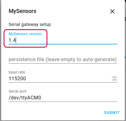
      Your assumption that it is a version issue seems correct, but you can't fix it by specifying a version in YAML when you configured the integration via the GUI.

      Could it be that you forgot to adjust the MySensors version during setup? If so, delete it and create a new one. (I don't think you can make changes to existing MySensors integrations (yet))

      mysensors_gui_version.png

      child_id 8 already exists in children of node 0, cannot add child [...]

      That's nothing to worry about. Those warning appear every time you boot up a node that has been presented to Home Assistant before already. It's helpful in situation where you accidentally assign a sensor / child ID twice to different data types or re-assign a previously existing node ID to a completely new node.

      posted in Home Assistant
      BearWithBeard
      BearWithBeard
    • RE: Missing sensor in home assistant integration

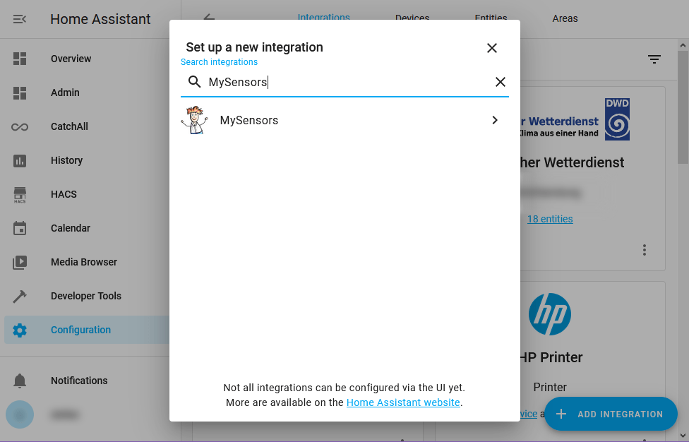
      @cnerone When you're logged into your Home Assistant instance, click "Configuration" in the sidebar, then "Integration" on the top of that page. Then click the big blue "+ Add Integration" button in the lower right corner and type MySensors in the searchbar that pops up.

      ha-find-mysensors.png

      posted in Home Assistant
      BearWithBeard
      BearWithBeard
    • RE: GatawayESP8266 - Compile error

      @skom Welcome! You're doing nothing wrong.

      It looks like some changes in the 3.0.0 release of the ESP6266 core that came out a few days ago is breaking most if not all MySensors example sketches for boards included in that package.

      I don't know what is causing this. It seems to be related to the PSTR macro - maybe someone with better understanding of this should have a look at it.

      As a workaround, you can downgrad the ESP8266 core from 3.0.0 to 2.7.4 in the Arduino boards manager and it should compile just fine.

      posted in General Discussion
      BearWithBeard
      BearWithBeard
    • RE: Node to Node ACK

      @anderBAKE When a node to node communication fails, MySensors will automatically fall back to the default route via the node's parent, so that ultimately the gateway can try to reach the destination node. I'm not sure if you can change that behaviour without touching the library code. But if you don't mind, a small change in MyTransport.cpp should do the trick.

      Change the following starting on line 548...

      if (destination > GATEWAY_ADDRESS && destination < BROADCAST_ADDRESS) {
      	// node2node traffic: assume node is in vincinity. If transmission fails, hand over to parent
      	if (transportSendWrite(destination, message)) {
      		TRANSPORT_DEBUG(PSTR("TSF:RTE:N2N OK\n"));
      		return true;
      	}
      	TRANSPORT_DEBUG(PSTR("!TSF:RTE:N2N FAIL\n"));
      }
      

      to the following...

      if (destination > GATEWAY_ADDRESS && destination < BROADCAST_ADDRESS) {
      	// node2node traffic
      	if (transportSendWrite(destination, message)) {
      		TRANSPORT_DEBUG(PSTR("TSF:RTE:N2N OK\n"));
      		return true;
      	} else {
      		TRANSPORT_DEBUG(PSTR("!TSF:RTE:N2N FAIL\n"));
      		return false;
      	}
      }
      

      This will drop out of the transportRouteMessage() function returning false to the send() function if the N2N communication failed.

      Note that, after this change, the node will not fall back to the default transport route anymore.

      Maybe this could be made an optional feature by introducing something like #define MY_DISABLE_N2N_FALLBACK to MyConfig.h?

      posted in Troubleshooting
      BearWithBeard
      BearWithBeard
    • RE: Where did everyone go?

      The availability of inexpensive commercial products surely is a factor for less interest in DIY solutions like MySensors. Chinese companies are flooding another market once again. Just look at Xiaomi's Aqara and Mijia range of products and their compatible clones. They offer at least a dozen of different sensors and actors in neat little enclosures with either ZigBee or BLE connectivity, many of which are commonly available for much less than 10 USD a piece in sales.

      In this view I get frequently asked by friends and relatives why I keep "wasting" so much time building my own devices when I could just buy some like they do and integrate them into Home Assistant or HomeKit with the flick of a switch.

      I always respond to them that - apart from privacy and reliability concerns against devices with a forced internet connection, as has already been mentioned by some of you - I actually enjoy the whole process from prototyping electronics to managing a home server. It's a hobby and I learn new things through it. Three years ago, I could barely read basic circuit diagrams - here I am, comfortably soldering self-designed all-SMD PCBs, enjoying programming so much that I branched out into other areas and started developing web apps. I can at least attempt to repair faulty electronics - and have been successful at times - instead of throwing them away and wasting resources.

      The whole DIY process forces me to think about my requirements and constraints. To think about what I actually need instead of what I want or could buy to fill a hole.

      MySensors is fantastic for someone like me. It is fairly accessible with commonly available components, with the option for much more powerful hardware, if needed. Wireless communication can be remarkably reliable. Other than ESP-based devices, MySensors nodes can be incredibly energy efficient for battery use. It's not polluting my WiFi, nor invading my privacy through cloud services. And although you might say it has gotten quieter in the forum, there's still always someone around to help if you're stuck. It's just that MySensors is strictly DIY, as @monte pointed out. You can't just buy a commercial device, upload a MySensors sketch to it and be done.

      That's probably not the answer to the question where everyone went, but rather why not many new come in. Maybe it's a hindrance for new users these days? Because the "DIY aspect", that's now often obsolete, was just a necessary evil for many? Or, as my friends ask, why waste your time with that?

      I guess you either have to have a specific mindset and interest to pick this up as a hobby with some dedication, or your requirements are so specific that no commercial product suits them, so that the pressure to DIY is high enough to bring yourself to do so. If not, the big home automation youtubers may show you the convenient way to quick satisfaction.

      posted in General Discussion
      BearWithBeard
      BearWithBeard
    • RE: Best password manager?

      Regarding antivirus. I'd say no, you don't need antivirus software on Linux. To my best knowledge, viruses and malware for Linux are still very, very rare, due to the Linux desktop / end user market share being tiny. No big malware campaign would specifically target Linux users, since the potential targets shrink from something like a 90% Windows userbase to like 1% Linux users. Unless you install software from shady repositories (think pirated software) or are directly targeted (as in they're specifically after your stuff, not someones), the risk of getting a virus should be pretty low. Follow best practices like avoid loging in as root / super user, compare checksums, think twice before granting programs elevated privileges, install updates regularly, etc.

      Linux seems to be rather well protected against threats anyway. Almost all network equipment runs on some sort of Linux. Most webservers are running a Linux. Maybe I'm wrong, but I bet most of them don't deploy a dedicated anti virus software, other than maybe for file or mail servers, to protect Windows clients.

      Wikipedia keeps a list of known Linux malware and points out that "few, if any are in the wild, and most have been rendered obsolete by Linux updates or were never a threat".

      On Windows, I'd say you're generally good if you use the Defender / Windows Security that comes with it. It provides more or less the same protection against threats as the big name commercial products and doesn't come with tons of bloatware, AI-based voodoo, invasive DLL injections into other software and stuff or accompanying browser extensions, which unnecessarily increase the system's attack surface.

      I guess it's worth mentioning, that antivirus software can be harmful, too. Security software isn't safer or more bug-free than other software. And since many antivirus suites integrate deeply into the OS, malware targeting antivirus software has an easy job infecting the system.

      Independently from the chosen OS, the best protection is to keep it and all software up-to-date so that known vulnerabilities can be closed or at least mitigated as soon as possible.

      posted in General Discussion
      BearWithBeard
      BearWithBeard
    • RE: Best password manager?

      @NeverDie I'm not sure how exactly those anti blocker services work, but I think they watch the browser environment, DOM tree or the loaded resources for changes and if they detect deviations from the expected state, they can conclude that some sort of blocker is installed.

      So yes, uBlock origin can be detected, as should be any extension that actively modifies websites, depending how good they are in this cat-and-mouse game. But it's impossible for me to tell how much that affects your daily browsing experience, since you and I are most likely visiting different websites. For me, there's actually only one regularly visited website that doesn't let me in unless I disable uBlock.

      I'd recommend uBlock origin over others, because it's fast and easy on hardware resources. It has more options and features than Adblock Plus (whose filter syntax it supports), as it doesn't only use filter lists, but can also block scripts and network requests to third party servers and you are free to adjust that for every site individually. It's easy to use, with optional advanced features and has a decent documentation.

      uMatrix could be considered a browser-based firewall which allows you to define rather granular rules for different content types (including cookies) per domain. It's definitely not a tool for non-technical users, as it breaks a lot of websites per default. uBlock origin includes a simplified form of uMatrix's features, but it's optional to use them. uMatrix doesn't seem to be in active development for more than a year as I just found out. Still works great though.

      posted in General Discussion
      BearWithBeard
      BearWithBeard
    • RE: Best password manager?

      Yeah well. Some of those "holes" in password managers are conceptual. You can't display a password or copy it to a clipboard without exposing it. I guess we have to accept that no software is 100% secure and that nobody can ever guarantee such a thing. A lot has to come together before those flaws become a serious threat - and what's the alternative anyway?

      Regarding browser extensions: While it's true what Brave is saying, I think it's the wrong conclusion to ditch extensions altogether. Websites themselves, even trustworthy ones, can be malicious. That is because most websites today load content from third parties like advertising or content distribution networks, for tracking purposes and to deliver targeted ads, regionally cached versions of the website or frequently used JS libraries like jQuery. If any of those third parties / CDNs gets compromised, attackers can inject harmful javascript into countless websites. The NYT, Yahoo and Spotify were rather famous victims* spreaders. Even Google's DoubleClick, one of the leading ad servers, has served malware before. (see malvertising on wikipedia).

      I understand that there are website owners who rely on ads to fund their projects, and one can always make exceptions for them or compensate through different means (subscriptions, donations,..), but I would never use a browser without any sort of ad- or scriptblocker like uBlock origin or uMatrix these days. I prefer to know and decide on my own which resources and from where they are loaded. They also help to restrict cross site tracking.

      Another nice side effect - which may confirm Brave's "3x faster" than Chrome claim - most websites load much faster. Take the NYT frontpage as an example:
      No blocker: transferred 28MB in 356 requests, which took 4.43s to load; keeps loading in new images, videos and other resources from third parties every minute
      With Blocker: 4.14MB in 58 requests, which took 1.76s; does not load anything from third parties afterwards

      It's either that or disable javascript entirely in the browser, which will render many websites useless.

      * I'm reluctant to call a website a victim in this case if they knowingly load content from third parties, accepting all the risks involved, but deny any responsibility in case they in turn cause harm to their customers / visitors.

      posted in General Discussion
      BearWithBeard
      BearWithBeard
    • RE: Best password manager?

      All password managers are a compromise between security and convenience. Those integrated into browsers seem to distinctly favor convenience. Yes, Chrome may sync the credentials encrypted to the Google cloud and they may be locally secured via the OS account login, etc. But did you ever need to authenticate if you tried to access those passwords? Firefox isn't much different - once you're logged into the OS, all Firefox-managed passwords are just three clicks away (unless you opt in to use a master password).

      I'd be surprised if someone or something (like malware) that has access to your PC won't be able to read and copy credentials from a browser, at least while the browser is running. Browsers store the credentials in the same location on all PCs, so I assume there is already specialized malware that automatically crawls those locations and kindly "asks" the browsers through their APIs to decrypt them.

      I guess it's worth mentioning that dedicated password manager application that you keep running and unlocked in the background all the time, might also leak some confidential data into memory under certain circumstances. Here's a case study that examined how 1Password, Dashlane, KeePass and LastPass could leak data: https://www.ise.io/casestudies/password-manager-hacking/

      posted in General Discussion
      BearWithBeard
      BearWithBeard
    • RE: Missing sensor in home assistant integration

      Welcome @Petervf !

      I think what throws Home Assistant off is the mismatch of S and V types in the node sketch:

      MyMessage msg(CHILD_ID, V_LEVEL);
      present(CHILD_ID, S_TEMP);  
      

      Since you're faking and trying to build a temperature sensor, you should use V_TEMP instead of V_LEVEL.

      You also may need to manually remove the conflicting child object (or the whole node object, if that's easier for you) from the persistence file and restart Home Assistant. Power down the MySensors node beforehand, so it can't push new data into the file between you editing it and restarting HA.

      Try to stick with S and V type combinations that match the listing on the serial protocol overview.

      For Home Assistant specifically, I think you must match S and V types to any combination listed in this dictionary of sensor types to appear in the UI.

      Edit: I remembered that there is a page dedicated to the MySensors sensors integration in the Home Assistant docs that also lists the supported types. So no need to crawl through the code base for this.

      I also noticed that the sketch you posted above is very similar to the example on that page. I guess you just overlooked to adapt the V type accordingly.

      posted in Home Assistant
      BearWithBeard
      BearWithBeard
    • RE: while (!sensor.begin()) error

      @maddhin The while / if won't work here, since SparkFun's implementation of the begin() function doesn't return a value, as both the compile error and @electrik suggest.

      Take a look at the SparkFunHTU21D.h header, where the function is defined:

      void begin(TwoWire &wirePort = Wire); //If user doesn't specificy then Wire will be used
      

      Its return type is void. It returns nothing. While and if conditions need something to compare, so the function would need to be a bool begin(...) or some other simple numeric type. Only then can a while or if clause determine if a condition is true (non-zero) or false (zero).

      In other words: SparkFun doesn't test if the sensor has been initialized properly, so you can't either.

      posted in Troubleshooting
      BearWithBeard
      BearWithBeard
    • RE: GUIDE - NRF5 / NRF51 / NRF52 for beginners

      @electrik Good to hear. And yes, I think you are right. I'll swap them and change the naming to RXI and TXO to clarify the directionality. Thanks for the hint!

      posted in Development
      BearWithBeard
      BearWithBeard
    • RE: Best password manager?

      @NeverDie Yes, LastPass vaults may have been secure as long as the master password couldn't be cracked, but it could have been worse, too. And who knows if (or when) they will be hacked again.

      Maybe I'm too paranoid here, but I think data stored in someone else's public network is inherently insecure. You have to trust that a company protects some of your most valuable data, that they are not deceiving you with false promises and that their security engineers are more skilled than the black hats.

      Remember the Ubiquiti hack recently? Attackers gained access to customers' cloud managed devices, by gaining root access to Ubiquiti's AWS cloud instances and S3 buckets via credentials stored in an IT employee's LastPass cloud account. What could happen if a key LastPass employee becomes a victim of a social engineering attack? Do they really have no master key or other way of decryption? With upwards of 25 million users storing their login credentials, LastPass is an attractive target for hackers.

      Sure, a cloud-based password manager is still much safer than using the same password everywhere. The question is, where are your passwords more secure? In the hands of a company that can hire highly skilled security experts to protect the data of millions publicly, or in our own incompetent hands, stored locally, below the radar level of hackers and where nobody other than us has access to - well, unless we are directly targeted of course. Both ways have their own set of risks.

      I personally prefer self-hosted, local or offline solutions over anything cloud- or account-coupled wherever that's an option.

      Bitwarden has been mentioned a few times now. Apparently it can be self-hosted, too. Guess I should have a look at it sometime!

      posted in General Discussion
      BearWithBeard
      BearWithBeard
    • RE: Best password manager?

      Almost 1.5k passwords? That's crazy! 😄 I guess I'm slightly above average with my 99 passwords.

      LastPass? Haven't they been hacked multiple times? Their browser addons leaked passwords, too. They also seem(ed) to (have) expose(d) potentially sensitive data in clear text when you stored a website.

      KeePass is my preferred password manager. It's free, open source, recommended by a couple of European IT / security authorities, has been audited at least twice, and most importantly:

      It doesn't require any accounts, cloud or internet connection whatsoever. Your stuff is stored locally in an encrypted database. The downside is that KeePass is most likely not as "easy" or user friendly to use as LastPass. You have to take care of syncing your database across devices yourself, e.g. by using a self hosted NextCloud or with triggers.

      KeePass is natively available on all desktops, there are ports for smartphones and many plugins for different use cases - private key management, QR codes, backup and sync, ...

      posted in General Discussion
      BearWithBeard
      BearWithBeard
    • RE: GUIDE - NRF5 / NRF51 / NRF52 for beginners

      @electrik Yeah, I ran into that issue, too. Not sure if that's the proper way to solve it, but I add a custom board directory to the build flags in platformio.ini ...

      build_flags = 
      	-I $PROJECT_DIR/boards/generic
      

      ... and copied the board variant files from .platformio/packages/framework-arduinonordicnrf5/variants/Generic/ to boards/generic/ in my project folder. Changes made in here aren't ignored or overwritten by global PIO definitions.

      posted in Development
      BearWithBeard
      BearWithBeard
    • RE: A tiny BME node - BME280 on ATtiny85

      @chamroeun-ou I used the example sketch from the OP further up in this thread (direct link). The relevant defines are also mentioned in the software section of the first post.

      You need to add the following to your sketch to get rid of the compiler errors:

      #define WDTCSR  WDTCR   // WDT Control Register
      extern void serialEventRun(void) __attribute__((weak));
      

      Note that ATtinys aren't officially supported by MySensors. Although they may work fine in many instances, you are basically on your own if you run into issues. There simply aren't many people who use MySensors on ATtinys.

      You're much more likely to find help if you use a more common MCU, like the ATmega328P. You'll find a list of MySensors-supported architectures on the Overview page.

      posted in My Project
      BearWithBeard
      BearWithBeard
    • RE: A tiny BME node - BME280 on ATtiny85

      @chamroeun-ou I'm sorry, I was under the impression that you want to rebuild the OP's project, since there was no mention of different sensors etc.

      Regarding the ATtiny85: How would you have used both SPI and I2C together in the first place? Both are implemented through a single USI and have to share the same OI pins.

      Regarding the ATtiny167: I don't think I have an ATtiny167 at hand currently, so I can't test if it'll actually work, but the OP's example code compiled fine for me. I just had to comment out the the external interrupt flag register redefinition (//#define EIFR GIFR), since it is implemented in the same way it is on the ATmega328P for example.

      Processing attiny167 (platform: atmelavr; board: attiny167; framework: arduino)
      -------------------------------------------------------------------------------
      PLATFORM: Atmel AVR (3.3.0) > Generic ATtiny167
      HARDWARE: ATTINY167 8MHz, 512B RAM, 16KB Flash
      PACKAGES:
       - framework-arduino-avr-attiny 1.5.2
       - toolchain-atmelavr 1.70300.191015 (7.3.0)
      RAM:   [=======   ]  65.0% (used 333 bytes from 512 bytes)
      Flash: [=====     ]  50.5% (used 8274 bytes from 16384 bytes)
      

      The ATtiny167 has dedicated SPI and I2C interfaces and IO pins, so it should be possible to use it as a MySensors node with an SHTC30 sensor. There's plenty of free space, too.

      posted in My Project
      BearWithBeard
      BearWithBeard
    • RE: A tiny BME node - BME280 on ATtiny85

      @chamroeun-ou I think it's actually quite fascinating that you can fit MySensors in less than 5kb of memory! Consider all the things the library does behind the scenes and that this includes all the required dependencies.

      Try using your BME280 on the SPI bus, which you need anyway for the transceiver. This should shave off about 800 bytes or so. It still fits on ATtinys with 8kb flash using the example sketch posted above (direct link).

      Processing attiny85 (platform: atmelavr; board: attiny85; framework: arduino)
      -------------------------------------------------------------------------------------
      PLATFORM: Atmel AVR (3.3.0) > Generic ATtiny85
      HARDWARE: ATTINY85 8MHz, 512B RAM, 8KB Flash
      PACKAGES:
       - framework-arduino-avr-attiny 1.5.2
       - toolchain-atmelavr 1.70300.191015 (7.3.0)
      RAM:   [=======   ]  65.8% (used 337 bytes from 512 bytes)
      Flash: [==========]  97.2% (used 7960 bytes from 8192 bytes)
      
      posted in My Project
      BearWithBeard
      BearWithBeard
    • RE: New simply node sensor project - please some advise

      @DenisJ Do NOT leave out decoupling capacitors for the MCU, because you may run into stability issues without them. Ideally, you'd place one 100 nF MLCC as close as possible to every VCC pin. But in my experience it's fine to use one MLCC for the two VCC pins that are next to each other on the ATmega328P-AU and one MLCC for the AVCC pin.

      It's also advised to connect AREF to ground through a 100 nF MLCC to make it more immune to noise if you are using the internal reference to read the battery voltage. Otherwise, if you don't use the ADC at all, just leave it unconnected.

      @DenisJ said in New simply node sensor project - please some advise:

      p.s. in the mean time I found this one that have only 7 mΩ MSR
      Do you think it's ok please ?

      Pay closer attention to the specs of the parts you pick. This tantalum cap is rated for 1.8V only. It'll fail before you get your first measurements from this node.

      If you choose to stick with tantalum for their compact size, opt for one that's rated for 10V, or maybe 6.3V. If you run them at 3V, they should be roughly in their "sweet spot" regarding DC leakage.

      Speaking of leakage current: Larger capacitors should be able to help stabilize the voltage further when the RFM69 is transmitting, but the leakage current increases with larger capacity. A high leakage current can noticably cut down on the total battery lifetime, as a low current consumption during sleep is most important for long lasting batteries in devices like this.

      Although the RFM69 will likely draw considerable more than your multimeter shows (I guess it's too slow to show the "real" peak current; IIRC datasheet states 45 mA peak for non-H RFM69 and up to 130 mA for the H version), I think about 470 µF should be a good compromise here.

      If you don't mind the physically larger size, consider using an electrolytic capacitor instead. They are safer to use and usually achieve lower DC leakage currents. I can personally recommend the Nichicon UMA / UMR series. You may use the electrolytic (or tantalum) capacitor in conjunction with a lower capacity (~10 µA) MLCC.

      You could also get a few large capacity MLCCs instead of the tantalum, as @skywatch suggested. With MLCCs you typically don't have to worry about DC leakage, but note that their operating capacity reduces drastically, the closer the applied voltage is to their rated voltage. For example, a 100 µF MLCC rated for 6.3V may only have 60µF at 3V or 30µF at 6V. But you can always add multiple in parallel.

      Those are all viable options.

      posted in Hardware
      BearWithBeard
      BearWithBeard
    • RE: Battery life calculator

      @DenisJ With 120 wakeups per hour as per your calculator screenshot, you'd wake up every 30 seconds instead of once every 2 minutes. 😉

      You should easily be able to get more than a year of runtime with that hardware setup and the mentioned thresholds for temp/hum.

      posted in Hardware
      BearWithBeard
      BearWithBeard
    • RE: Battery life calculator

      @DenisJ Well, the result of the calculator is right, but are your inputs, too? They seem rather pessimistic for a temp/hum sensor node. Did you measure the wake time of 2s?

      In my experience, sending a message takes 80ms on average. Updating and reading a sensor may take 20 - 250ms depeding on the sensor and bus speed. A full wake cycle will likely be shorter than 500ms in this scenario. You could take two timestamps with millis() - right after waking up and before entering sleep - to get an estimate of the actual wake time.

      If you read the sensor every minute, but send new values only every 5 to 10 minutes, two AAA alkaline batteries should rather last two years than two month (provided that all components can work in the full voltage range of the batteries).

      Note that writing lots of debug messages to the serial port or using blinking LEDs as RX/TX indicators may add a considerable amout of time spent in an active state.

      posted in Hardware
      BearWithBeard
      BearWithBeard
    • RE: I cannot add new nodes, After I get support in Home Assistant,

      I added a new node(ralay id:50), again home assistant(HA) was not added. How can I send a new value from the Relay?

      You need to send a message at least once for it to appear in Home Assistant. Use something like this:

      bool initialMessageSent = false;
      void loop() {
        if (!initialMessageSent) {
          send(msgRelay.set(currentRelayState));
          initialMessageSent = true;
        }
      }
      

      After you manually injected a message via MYSController, Home Assistant started to list the new entity in the UI. So yes, that's exactly what Home Assistant required. If you take care of that within the sketch as shown above, you don't need to do it manually.

      But It seems to be disconnected from the network every time a command comes from HA.
      do you think this is normal?

      No, I wouldn't consider that normal. What do you mean by "disconnected"? Does the node stop working completely after receiving a message from HA? Doesn't it respond to consecutive commands?

      Does the debug output (using #define MY_DEBUG in the relay node sketch) hint at something? Sharing your sketch may help us find the issue.

      posted in Troubleshooting
      BearWithBeard
      BearWithBeard
    • RE: Gateway to support dual radio

      @Westie That feature can also be used with the Arduino Nano, or any other ATmega328P-based board.

      I had NRF24 + RFM69 running for a couple of days using a Nano as an Ethernet MQTT gateway and it worked fine as far as I remember.

      posted in General Discussion
      BearWithBeard
      BearWithBeard
    • RE: I cannot add new nodes, After I get support in Home Assistant,

      If I understand you right, this happened:

      -> You created a new node with ID 6 as a relay and connected it. Home Assistant didn't list the new node.

      Most likely, because you didn't send an initial value. If a sensor / child has not sent a value at least once, HA won't display it, because there is nothing that it could display. (No value, or null, isn't the same as a value of 0 / zero. The latter could be interpreted as "off", but not the former.)

      Since the MySensors integration is now configurable via the UI, every node must be registered in Home Assistant's entity registry. That means, that every MySensors node and its children get a persistent unique_id, which doesn't change after uploading a different sketch.

      -> The relay appeared in the UI after some time.

      You did something to trigger the relay or updated the sketch to send the relay state at least once when you were researching the problem. Now that HA has a value to associate with the entity, it is able to display something in the UI.

      -> You uploaded a different sketch for a motion sensor to the Arduino, but kept using the same node and child ID.

      Home Assistant recognized that this is the exact same device as before, because the unique_id didn't change and as far as Home Assistant is concerned, you are not supposed to change this ID.

      The data stored in the entity registry has precedence over other data sources like the mysensors.json file, so HA will continue to treat every sensor with the same child ID on node ID 6 connected to the same gateway as a relay and name it "Relay 6" by default.

      Some possible workarounds are:

      • Rename the "Relay 6" in the Home Assistant UI.
      • Delete the entity of the relay sensor from the UI using the "DELETE" button in the lower left corner of the modal window. Then power up the Arduino with the new motion sensor sketch.
      • Shut down Home Assistant and delete the registry entry of the relay sensor manually from the core.entity_registry JSON file (located in config/.storage/). Be sure to backup the file before doing so!
      • Choose a different node / child ID for the motion sensor and "disable" the relay entity in the UI.

      I think, since MySensors nodes are now uniquely registered in Home Assistant, it should be "best practice" to statically (manually) assign node IDs and be mindful about it. Like, use different node IDs for different node types to avoid conflicts with the registry. If you ever used ID 5 for a temperature and humidity sensor and you stopped using it, avoid reusing the same node ID for anything else than another temperature and humidity sensor node.

      Personally, I use ID ranges for nodes with the same function. Like, all node IDs from 30 to 49 are reserved for door and windor contact sensors.

      posted in Troubleshooting
      BearWithBeard
      BearWithBeard
    • RE: Gateway to support dual radio

      @Westie Yes, with the 2.4 (alpha) development version of the MySensors library you can combine multiple transports in a single network. Defining both the NRF24 and RFM95 in the gateway sketch should be all you need to do.

      See here for more info including example sketches:
      https://forum.mysensors.org/topic/11135/something-s-cooking-in-the-mysensors-labs/18

      You can download the latest 2.4 release from here:
      https://github.com/mysensors/MySensors/tree/development

      posted in General Discussion
      BearWithBeard
      BearWithBeard
    • RE: best solution to monitor and log power usage

      @NeverDie The power metering IC is an ADE7953 that can measure active, reactive, and apparent energy.

      The API states that it measures real power in the description:

      power | number | Current real AC power being drawn, in Watts

      posted in General Discussion
      BearWithBeard
      BearWithBeard
    • RE: best solution to monitor and log power usage

      @NeverDie Working temperature means ambient in this case. Quoting the Allterco CEO:

      Max ambient temperature is 40 degree. With no load PCB temperature is 55-60 degree. At MAX load continuesly is 87-90 degree.
      Heating protection will switch off device at 95 degree.
      All parts inside are 105-120 degree certifed for continuous usage.

      Original source: https://www.facebook.com/groups/1686781668087857/permalink/2054834997949187/

      posted in General Discussion
      BearWithBeard
      BearWithBeard
    • RE: best solution to monitor and log power usage

      @NeverDie Oh, if you refer to the second set of infrared images - those with the relay as the hottest spot - they are taken from a Sonoff Basic. The other set is the Shelly 2.5.

      In the meantime, I found some images of Shelly 2.5 with burnt spots and antennas pierced by the screw terminal pins. Reports of bad solder joints and such (German source with images). It seems that this was a faulty batch of devices from early 2019 which has been recalled. Never the less, I just opened the enclosure of my two Shelly 2.5 and I can confirm that they are obviously of a newer revision (bought in december 2020. the PCB was produced in July 2020, according to the silkscreen). The antenna is now attached to the upper part of the enclosure so that it can't be pierced by the pins and the cable is not touching the resistor R42 that is getting so hot in the FLIR images, although it's routed around the PCB in that corner. All pads and terminals look clean and nicely soldered.

      The relays are 10A 250VAC rated HF32FA-G/012-HSL1 models.

      posted in General Discussion
      BearWithBeard
      BearWithBeard
    • RE: best solution to monitor and log power usage

      @NeverDie Interesting find. But according to this GitHub issue, that fix only concerns those Shellys that have been flashed with certain versions of Tasmota or ESPhome, where the GPIOs had been misconfigured. To me, that sounds like it was an issue on top of the inherently higher temperature of the Shelly 2.5, doesn't it? I assumed the Shelly 2.5 temperatures were higher because of the second power metering circuit on board, potentially dissipating more heat through resistors.

      Anyway - you are right that the Shellys have over-temperature protection which should kick in at 90 to 95°C and I can only assume that all components are rated for temperatures above that. So in that regard it should be fine if the Shelly 2.5 operates at higher temperatures than the other models. The device is completely encased, which lowers the risk of scorching wire insulations or terminals with lower temperature ratings that might touch it.

      It may just be that it triggers the OTP earlier than single channel Shellys when two (high?) loads are connected. Then again, installing two single channel Shellys in a single power outlet could potentially be even worse, as you then have two heat-emitting devices in close proximity. Giving it a try may be the only way to find out.

      posted in General Discussion
      BearWithBeard
      BearWithBeard
    • RE: best solution to monitor and log power usage

      @NeverDie While I'm still sitting on a box full of various Shelly devices waiting to be installed (hardware stores are closed since months, due to lockdown...), I'd like to point out that the Shelly 2.5 models you linked are apparently not suitable for continuous loads. Lots of peope report that they get quite hot, unlike other models. They are meant to be used for roller shutter control or other momentary loads. With that in mind, I don't think they are very useful as a power meter. Shelly has dedicated power measuring relays like the 1PM, EM, the 3-phase EM3, or Pro4 for DIN rails, as well as the WiFi plugs Plug and Plug S.

      You don't have to use their cloud service, nor do you need to reprogram them. Use their mobile app, wire them up in your favourite home automation controller or use the provided REST or MQTT APIs directly to set them up and collect data. Regarding power meter measurement intervals: at least the Shelly 1PM seems to be able to report down to a per minute scale.

      But yeah, the fact that they fit into power outlets and that you can use them freely without any external services is pretty nice.

      posted in General Discussion
      BearWithBeard
      BearWithBeard
    • RE: Best PC platform for running Esxi/Docker at home?

      Building quiet PCs is so addictive. Once you're used to it, every little rattling becomes an annoyance. It didn't took long until I had to get rid of all spinning HDDs in favor of SSDs. And as soon as everything was dead silent... I bought myself a clicky mechanical keyboard, oh well.. 😄

      Nanoxia Deep Silence and Fractal Design Define are indeed nice sound-insulated cases for quiet builds with plenty of space and features.

      For silent cooling, I can recommend be quiet (especially the Silent Wings fans) and Noctua (basically everything). The latter is quite pricy though.

      posted in Controllers
      BearWithBeard
      BearWithBeard
    • RE: Best PC platform for running Esxi/Docker at home?

      @NeverDie said in Best PC platform for running Esxi/Docker at home?:

      At any rate, it looks as though the idle wattage for just the Ryzen 5 5600X cpu is around 26 watts:

      See what I mean with "other reviewers may get different results"? ThinkComputers says 26W idle. Tom's Hardware says 13W. AnandTech says 11W. TPU says 50W (whole system). Who is right? It's unfortunate that there is no standard testing procedure every reviewer adheres to.

      Part of the different results may be due to mainboard selection. Some (I don't know how many and if they are rare or the majority) AM4 mainboards seem to be rather power hungry. Especially those with an X570 chipset. Some may add another 10 to 20W to the total power consumption, even if you use the same CPU. See here for example.

      26w is manageable with a quiet fan.

      Oh yeah, absolutely! Even under load. My 80W Xeon sitting right next to me here is inaudible for most people unless they hold their ear close to the PC case.

      Oh, and please note that I'm not trying to sell you the 5600X just because I used it as a comparison a few times. IMHO, all CPUs in that category are grossly overpowered for the average home server unless you know that you will need it sooner or later.

      posted in Controllers
      BearWithBeard
      BearWithBeard
    • RE: Best PC platform for running Esxi/Docker at home?

      The cTDP is generally only provided for APUs (CPU + GPU on a single chip). It allows OEMs to easily limit the power draw (mainly the all core boost clock) to match the CPU to their thermal design requirements. That's why two equally equipped notebooks can have vastly different performance results. It's a pity that OEMs almost never advertise their cTDP setting.

      The desktop CPU market is a little different. Thermal design isn't that critical, CPUs are also sold directly to end users, etc. While it may depend on the mainboard manufacturer to enable the cTDP setting in their UEFI, it is generally possible to adjust it on desktop Ryzens as well. Many do that to find their efficiency sweet spot. I guess nothing could stop you from setting a 5600X's cTDP to 15W. That's what I did with my Athlon as well, albeit only from 25W to 15W. Besides the cTDP, there are other ways to increase efficiency: Lowering the PPT threshold, setting a negative vCore offset, etc. But that whole topic is too complex to explain or discuss here. You may search on PC hardware websites like AnandTech, Tom's Hardware, GamersNexus, Guru3D and such for more details if you're interested.

      Here's a 5600X review by Tom's Hardware. They suggest that it draws 13W in idle at stock settings, which are 20% of the nominal 65W TDP. Other reviewers may get different results, due to hundreds of different combinations of configurations, hardware choice and measurement methods. I assume that you can reduce those 13W even further with some adjustments, but don't take my word on that. Unfortunately, I don't own a Ryzen right now to test that myself.

      That being said, I don't think you can realistically underclock a desktop CPU to match the power draw of their mobile pendants. So the mobile CPU may always be more economical.

      Maybe the embedded lineup of CPUs like the Intel Xeon D or AMD V / Epic Embedded may suit you? They are generally more targeted towards industrial use and have far more connectivity options than those NUC-style mini PCs or notebooks. Commercial NAS vendors like Synology use those. Unfortunately, at first glance, it looks like both Intel and AMD solutions seem rather outdated at the moment.

      posted in Controllers
      BearWithBeard
      BearWithBeard
    • RE: Best PC platform for running Esxi/Docker at home?

      I get that efficieny is important for a device that runs 24/7, but looking at the options you have with a 5800U, I think you sacrifice a lot. How do you add hard drives for storage, via USB3? What about RAID? How do you know if the laptop's thermal design is sufficient for 24/7 uptime?

      Do not focus too much on the nominal TDP. It is basically just an approximation for the cooling solution required to achieve the rated performance of the CPU. In the specific case of AMD Ryzen CPUs, the rated TDP roughly equals the power draw in P0 state, which is the highest active power state the CPU can be in.

      For example, a Ryzen 5 5600X rated at 65W may draw 60 to 75W (once the thermal limit is reached and everything is settled in) under high demanding workloads (prime95 and such). Modern CPUs are smart enough to switch to quite efficient P-states when they have nothing to do, lowering the clock to the sub-GHz range, drastically reducing the core voltage. So if the CPU is idling, it may only draw 10 to 15% of the rated TDP - and a home server will likely idle 95% of the time.

      At this point, other components (mainboard chipset, hard drives and other peripherals, power losses of the power supply, ...) might start to contribute more to the total power consumption of the PC than the CPU itself. And I haven't even mentioned that you could underclock (which doesn't void warranty) the CPU the increase the efficiency even further.

      posted in Controllers
      BearWithBeard
      BearWithBeard
    • RE: Best PC platform for running Esxi/Docker at home?

      @NeverDie said in Best PC platform for running Esxi/Docker at home?:

      Were you using it for Esxi or Docker?

      I do not use any hardware virtualization / hypervisors. Just a regular Linux distribution as a host running Docker containers and other stuff.

      Is that some kind of carrier that it's affixed to, or is it all BGA on the other side?

      AFAIK, all Ryzen CPUs ending with an U or H are soldered BGA packages for the mobile OEM market. U indicates low TDP variants for long battery runtime, whereas H or HS stands for high performance setup.

      posted in Controllers
      BearWithBeard
      BearWithBeard
    • RE: Best PC platform for running Esxi/Docker at home?

      I'm still rocking a cute, little AMD Athlon 5350 APU (2GHz, 4C/4T, 15W TDP limit) with just 4GB DDR3. I bought it as a budget solution to learn about Linux and server stuff and never intended it to last for so long, but it's still keeping up just fine. Neither OpenMediaVault (Debian-based), nor Ubuntu Server were causing any hardware-related issues.

      It hosts about a dozen of Docker containers and a bunch of natively installed services for everything home automation, data collection and IoT. I have some self-hosted web services running and use it as a DNS server / firewall, NAS for media streaming and as a personal "cloud" storage for four household members. Despite the poor specs, it is powerful enough to serve multiple users simultaneously (DAAP, video streaming or other I/O tasks) while still managing all the network and IoT stuff in the background.

      I wonder, where would you get that Ryzen 7 5800U from? Isn't that a non-socketable BGA package meant for notebooks? If I had to build a new system right now, I would spontaneously go for a regular Ryzen 5 (maybe Ryzen 7, if the additional cores are really needed for VMs and such) and undervolt it to make it run more efficient. Depending on the mainboard selection, you can use ECC RAM and get up to 10x SATA onboard, which should be plenty for home use.

      posted in Controllers
      BearWithBeard
      BearWithBeard
    • RE: Relay Actuator with momentary (pulse) action

      @adds666 In receive(), note how you use relayPin:

        if (message.type == V_STATUS) {
      
          if (message.sensor == 7)  {
            if (message.getBool() == RELAY_ON) {
              digitalWrite(message.getSensor()-1+relayPin, RELAY_ON);
      

      relayPin is an array (const uint8_t relayPin[] = {3, 7};). If you use it without specifying an index, like you do here, you get a pointer to the first element, not the value of an element.

      Something like digitalWrite(relayPin[message.getSensor()-7], RELAY_ON) should work here. getSensor() returns 7, because you already checked for that two lines above. 7 - 7 = 0, which results in relayPin[0] and toggles the relay on pin 3.

      Also, note that you load the current relay state from EEPROM positions 0 and 1 in setup():

      for (uint8_t i = 0; i < MAX_RELAY; i++) {
        pinMode(relayPin[i], OUTPUT);
        //digitalWrite(relayPin, loadState(i)?RELAY_ON:RELAY_OFF);
        if (loadState(i) == RELAY_ON) {
      

      But you save the state to byte 7 in receive():

      saveState(message.sensor, message.getBool());
      

      Hope this helps you out!

      posted in Troubleshooting
      BearWithBeard
      BearWithBeard
    • RE: Commenting and chat seem to be broken

      @hek Can confirm. Didn't get any 405 responses nor pesky modals over the last few hours. Thank you!

      posted in General Discussion
      BearWithBeard
      BearWithBeard
    • RE: Commenting and chat seem to be broken

      Hmm, I also have an issue, although it's likely unrelated. Every few minutes, there are three or four consecutive polling requests - some of which are also quite slow (>500ms) - by the sockets.io script that are all responded with a 405 (method not allowed). Right after that, it switches protocol from HTTP2 to HTTP1.1 and sends another few requests, which now are all responded with a 200 (OK).

      It doesn't break anything as far as I can tell. It shows a "Looks like your connection was lost" modal in the bottom right corner and the forum's navigation bar shifts to the side (and sometime appears as if I'm logged out). After a few seconds, it's all back to normal. It just happens very frequently since a few weeks or so.

      I'm using Firefox (86), but I have seen it happen in Chromium-based browsers as well.

      mysensors-405.png

      posted in General Discussion
      BearWithBeard
      BearWithBeard
    • RE: Error During presentation

      Hey @sfozz

      Without further information about your setup, I assume that you have the MySensors integration in configuration.yaml configured incorrectly. It looks like you either didn't specify the MySensors protocol version at all or wrongly, in which case it defaults to the very old 1.4 protocol version that doesn't support many of the newer types like S_HVAC or S_INFO.

      It needs to look like this:

      mysensors:
        gateways:
          - device: ...
            # other things ...
        version: "2.3"
      

      Do not include the patch level (as in 2.3.2). It doesn't ask for the MySensors version used in the Arduino sketch, but for the protocol version implemented by pymysensors.

      posted in Home Assistant
      BearWithBeard
      BearWithBeard
    • RE: is there a list of supported MCU platforms?

      For the sake of completeness, there's also this graph on the overview page in the getting started section, which covers all (officially) supported architectures, internal and gateway transports.

      posted in Hardware
      BearWithBeard
      BearWithBeard
    • RE: Measuring battery voltage, which way is best?

      The URL is in an inline code HTML element and the CSS rule #article code {white-space: nowrap;} prevents long lines from breaking the layout, causing the (visual) truncation depending on the window size. Double-clicking or marking the whole line with the cursor gives you the full link, but you can't simply click on it to open the URL. A hyperlink would wrap (and be clickable).

      mysensors-code-link-wrap.png

      I assume this is only a temporary solution. It might be better though to replace it with a hyperlink tag or better, embed it like the external measurement example in the section below it (once it's added to the examples repo).

      @mfalkvidd Okay, understood. Managing external libraries in ArduinoIDE projects can be cumbersome and confusing. Just brainstorming here - two ways of clarifying that external libraries are required in a provided example sketch:

      • After including an external library, add a conditional #error preprocessor directive that checks if the library-specific header guard is defined. This doesn't address backwards compatibility issues though:
      #include <Vcc.h>
      #ifndef VCC_H
      #error You need to install Arduino_VCC version 1.x (URL)
      #error How to install libraries in ArduinoIDE: (URL)
      #endif
      
      • Provide a "Notice" box or something like that above the embedded sketch on the website: (quickly hacked together):
        mysensors-external-lib-note.png
      posted in General Discussion
      BearWithBeard
      BearWithBeard
    • RE: Bootloader for 168V 8Mhz 1.9v bod anyone?

      @skywatch Huh! I didn't know there was a ATmega168 with a V and had to look it up.

      Maybe I'm wrong, but comparing datasheets of both 168-variants and looking at some of the older Arduinos, I guess you could use a regular ATmega168 bootloader without any suffix. The Arduino folks seem to have done that with the 168V-based Lillypad for example.

      MiniCore for example provides a bootloader for a 1MHz 168 and the fuse settings (for BOD) seem to match as well.

      You may have a look at that unless you found a suitable 168V bootloader in the meantime.

      Edit: replaced all 186 with 168. 😊

      posted in General Discussion
      BearWithBeard
      BearWithBeard
    • RE: Measuring battery voltage, which way is best?

      Unless it gets integrated into the MySensors library itself, it may be easier for some people to use a little library for that purpose? Because it "hides" all the technical stuff, setting and reading the registers. I have been using Yveaux's Arduino_VCC library in the past, which works great. Anyway - it's always good to have options.

      posted in General Discussion
      BearWithBeard
      BearWithBeard
    • RE: 💬 Battery Powered Sensors

      @tssk I heard that people got rid of or at least reduced the coil whine by coating the windings of an audible inductor with non-conductive materials like epoxy resin or even hot glue to reduce the vibrations.

      Of course, I woudn't mess with expensive PC hardware, but I guess there's not much to loose with a cheap boost module like this.

      posted in Announcements
      BearWithBeard
      BearWithBeard
    • Security vulnerabilities in Home Assistant & custom integrations

      I know that some folks in here are using Home Assistant, but they may not all be visiting the HA website regularly. So I thought I'd share this info here.

      They have published two security disclosures recently, informing us about security vulnerabilities found in third party integrations (including HACS, commonly used to integrate Alexa and such), which allowed an attacker to access any file that is accessible by the Home Assistant process. Be sure to upgrade to Home Assistant Core 2021.1.5 or later and all custom integrations as soon as possible.

      More details as well as (all?) affected custom integrations can be found in the Home Assistant blog.

      posted in Home Assistant
      BearWithBeard
      BearWithBeard
    • RE: Filter node

      What about using MY_PARENT_NODE_ID on the nodes that should connect to a specific repeater? If you also want to prevent the node to connect to other repeaters as a fall back in case the specified parent is unavailable, combine it with MY_PARENT_NODE_IS_STATIC.

      #define MY_PARENT_NODE_ID 2 // Set node 2 as preferred parent
      #define MY_PARENT_NODE_IS_STATIC // Disables fall back
      posted in Feature Requests
      BearWithBeard
      BearWithBeard
    • RE: Senserbender gateway problem dtostrf.h

      Try to downgrade the SAMD core ("Arduino SAMD Boards" in the boards manager) to 1.8.9 and it should compile. They seem to have introduced some breaking changes with 1.8.10 (see release notes).

      posted in Development
      BearWithBeard
      BearWithBeard
    • RE: Library V2.x API error

      I don't think there's are direct causal relationship between the quality of a documentation and the number of users asking for help on a forum.

      People usually register to get help and you'll likely find that most people in this (or any) forum asked a question in their first post (me included) and most of them never came back after their issue has been solved or they lost interest. This forum has almost 10k registered users, of which 8k wrote five posts or less. From this we can't infer that most users trying to use MySensors encounter problems, nor that the documentation is flawed. That's just the nature of a support forum, or any forum, really.

      Regarding this forum specifically, my gut feeling tells me that most questions are related to connection issues between nodes, which are usually caused by wrong or flimsy wiring, weak power supplies, too much noise, range issues, etc. The solutions for those issues are documented in articles as well as the FAQ, but people are still asking.

      Maybe my gut feeling is wrong and it might be worthwile for us to browse through the troubleshooting forum. Comparing what people actually asked or were looking for and comparing it to how well those topics are covered in the articles and guides might be a more practical approach to improving the documentation.

      posted in General Discussion
      BearWithBeard
      BearWithBeard
    • RE: Library V2.x API error

      @skywatch Got it, you pretended to be a newbie all along. Was it too boring to show your intentions right away? 😄

      I understand your point, but I guess that brings us back to the discussion we had a few months ago about the state of the documentation / guides and how beginner friendly it needs to be and where it starts to be too verbose. IMHO, in the context of that page, it's fine and it should be clear that it isn't a complete sketch.

      If I can come up with a meaningful sketch that makes use of both timed and external interrupts without using additional libraries and such, I'll post it so that someone with rights to edit those articles can update it if they want.

      Edit: Well, not that meaningful, but it brings the point across and isn't too long:

      #define MY_RADIO_RF24
      #include <MySensors.h>
      
      #define CHILD_ID 1
      MyMessage msg(CHILD_ID, V_STATUS);
      
      #define INT_PIN 3
      #define LED_PIN 5
      bool ledState = false;
      
      #define SLEEP_TIME 9000000 // 15 min
      uint32_t sleepTime = SLEEP_TIME;
      int8_t wakeupReason = MY_WAKE_UP_BY_TIMER; // Initial value, will be set by sleep after the first run
      
      void presentation()
      {
      	sendSketchInfo("Sleep + Interrupts", "1.0");
      	present(CHILD_ID, S_BINARY);
      }
      
      void setup()
      {
      	pinMode(LED_PIN, OUTPUT);
      	digitalWrite(LED_PIN, ledState);
      }
      
      void loop()
      {
      	if (wakeupReason == digitalPinToInterrupt(INT_PIN)) {
      		sleepTime = getSleepRemaining();
      		// Do interrupt-triggered stuff here
      		// Sends the pin state when woken up by external interrupt
      		send(msg.set(digitalRead(INT_PIN)));
      	} else if (wakeupReason == MY_WAKE_UP_BY_TIMER) {
      		sleepTime = SLEEP_TIME;
      		// Do periodical stuff here
      		// Toggles the LED every 15 minutes
      		ledState = !ledState;
      		digitalWrite(LED_PIN, ledState);
      	}
      	wakeupReason = sleep(digitalPinToInterrupt(INT_PIN), CHANGE, sleepTime);
      }
      
      posted in General Discussion
      BearWithBeard
      BearWithBeard
    • RE: Library V2.x API error

      @skywatch

      arduino-interrupt-example.png

      Sorry, I don't quite follow. I don't think you want to say that the snippet is missing the MySensors.h include and such, are you?

      posted in General Discussion
      BearWithBeard
      BearWithBeard
    • RE: Library V2.x API error

      @skywatch You are referring to the snippet that combines sleep on timer with pin change interrupts?

      I just pasted that code in two randomly picked MySensor example sketches (UVSensor and ClearEepromConfig) and it compiled just fine (MySensors 2.3.2 and IDE 1.8.13). What kind of error do you get?

      Edit: If it complains about getSleepRemaining() not being declared, you may be using an older MySensors version. I think it has been added with 2.3.2

      posted in General Discussion
      BearWithBeard
      BearWithBeard
    • RE: CR2032 coin cells - expected life?

      cr2032-contact.png

      The graph above is from my oldest window contact that is still in service with its first CR2032. It has reported 2902 events in over a year (less than 8 wake cycles per day on average).

      cr2032-temp.png

      The second graph is from my oldest temperature & humidity node, also running off a CR2032. Since march 2020, it reported 180k data points (temp & hum every 5 minutes).

      Unfortunately I didn't configure them to report the battery voltage back then, but I took a reading with my DMM right now: The window node reads 3.041V and the temperature node 2.993V. What I'm trying to show is that nodes can run for years with a CR2032.

      The temperature node should be the most discharged CR2032 I have in use currently, so I have yet to find out at which voltage they stop working. But I think 2.8V should still be fine if you have enough capacity to counteract the voltage drop during transmission.

      If the battery in your node died suddenly, I guess the node may have failed to sleep for some reason. I had this issue before a couple of times and I can only assume that the node lost connection to the repeater and drained the whole battery in a find-parent-loop.

      Update (mid of Nov 21): The temperature & humidity node died a few days ago. It sent roughly 350k individual sensor readings over a span of 20 months. That's about the maximum lifetime I could expect with 12 wake cycles per hour.

      posted in Hardware
      BearWithBeard
      BearWithBeard
    • RE: Is it possible to request sensor status (via MQTT)?

      "Usually" is the correct term. You can request whatever you want using MQTT, but you need to handle the response manually inside the receive() function. This isn't an automatic internal process like the echo or ack response.

      void receive(const MyMessage &message)
      {
      	if (message.getCommand() == C_REQ)
      	{
      		switch (message.getSensor())
      		{
      		case 10:
      			// Send SSR 1 state
      			break;
      		case 11:
      			// Send SSR 2 state
      			break;
      		case 20:
      			// Send temperature sensor value
      			break;
      		case 40:
      			// Send humidity sensor value
      			break;
      		default:
      			break;
      		}
      	}
      }
      

      Note: It's best to not send a message from within receive() as it can cause all sorts of weird stuff, including recursive loops. Preferably, you'd set a flag and handle everything else in the main loop.

      posted in Troubleshooting
      BearWithBeard
      BearWithBeard
    • RE: No Ack reveive on gateway with button

      Welcome @mjchrist!

      Short answer: Check the return value of send() on the gateway, to see if a message has been successfully delivered an outgoing message (via Ethernet, MQTT, serial).

      Long answer: What you are referring to as an ACK should really be called echo instead to avoid confusion, because that is really what it does.

      bool send(MyMessage &msg, bool echo);

      If you set the echo parameter to true, you ask the destination node to echo the received payload back to the sending node. An echo is only being generated for messages that travel through the MySensors network. For example, if node 42 sends a message to the gateway (so that it can forward it to the controller), the gateway will echo the payload back to node 42. The same is true if the gateway is the sender and node 42 the destination.

      On the other hand, the boolean return value of send() will tell you that the sending node received an acknowledgment from the next hop. This next hop might be the destination if there's a direct connection between the two nodes, or any node that relays the message further to the destination, like a repeater.

      In the special case where the gateway sends a message (to the controller, so to speak), the return value of send() isn't the ACK from a MySensors-internal transport (like NRF24), but the confirmation that the message was successfully delivered via the outgoing transport layer which translates the message into a packet, a MQTT topic or string for the serial port.

      Oh, and by the way, please use isEcho() in favour of isAck(). The latter is misleading (IMHO) and deprecated. It will be removed with MySensors v3.

      And last but not least, MY_TRANSPORT_WAIT_READY_MS doesn't mean that the node (or gateway in this case) waits for n milliseconds until it starts establishing a connection (for the transceiver (NRF24), to be clear). Instead, it limits the time the node tries to establish a connection to n milliseconds, so that it can continue to work autonomously and do other stuff if it failed to do so.

      posted in Troubleshooting
      BearWithBeard
      BearWithBeard
    • RE: Here's a better crimping tool for Dupont, JST, and Molex

      I use the SN-01BM crimping tool for Dupont / JST-style connectors, which is basically a smaller version of the SN-28B that can't handle wire diameters bigger than 20AWG. It has only two crimping slots in the die. Mine is from "Plato" though, not from IWISS - not sure if they are resellers or a copycat. On photos, they look identical, apart from the color of the grips.

      I get nice crimps with a single pass for both insulator and conductor, but the crimp terminal needs to be inserted precisely. If inserted too deep or not deep enough, a second pass is needed to roll over the wings of both the insulator and conductor barrels in their full length.

      posted in General Discussion
      BearWithBeard
      BearWithBeard
    • RE: What did you build today (Pictures) ?

      Winter time is tinker time!

      mysensors-epd-node-clean.jpg

      This is a compact environmental sensor node with an E-Paper display. My goal was to have a decent screen-to-body ratio with a simple and minimalistic display, easy to read from a distance. It is the first design in which I did not use an ATmega MCU. It is also the first time that I used KiCAD instead of EAGLE, soldered no-lead SMD components and worked with an EPD.

      • It features a SHTC3 sensor to measure temperature and relative humidity and a VEML6030 to measure the ambient light, so that I can toggle lights or other appliances in the room based on temperature, humidity or light conditions.
      • I have also added a MEMS sensor (LIS3DH) to auto-detect the device orientation and rotate the EPD image accordingly and / or detect tap events to toggle between different display modes / data sets.
      • It can be powered directly from a 3V source or use the optional 3.3V boost circuit which accepts 1.5V or 3V sources.

      I finished soldering and testing all the components today and just started programming the rough "framework". Looks promising so far! But still lots to do, including finalizing the 3D printed enclosure. This is how it is supposed to look in the end:

      mysensors-epd-node-render2.jpg

      posted in General Discussion
      BearWithBeard
      BearWithBeard
    • RE: !TSM:ID:FAIL need help

      Welcome @robos!

      The gateway is sending an ID request via MQTT to the controller, but doesn't get a reply.

      From the Building a MQTT Gateway guide:

      NOTE: No controller supports dynamic ID assignment through MQTT. All nodes must have MY_NODE_ID defined in the sketch to work with MQTT. If you don't set MY_NODE_ID, nodes will complain with the message "!TSM:ID:FAIL".

      If you want to keep using MQTT, you have to add #define MY_NODE_ID n before(!) #include <MySensors.h>, whereby n may be any (unused) number between 1 and 254.

      For automatic ID assignment through the controller, select a different gateway, like serial or ethernet.

      posted in Troubleshooting
      BearWithBeard
      BearWithBeard
    • RE: Best practice for hardware ack and software ack when using a battery node

      @evb The indication handler will not only be triggered by the error message, but also by (almost) all internal messages, like registration requests, node and sensor presentation, nonce, discovery responses, find parent requests, OTA firmware upgrades and others. Basically everything that uses the default transportRouteMessage() function.

      It's up to you if this gives a wrong picture. If you want to know how reliable the uplink of node is, it's exactly what you would want to use, isn't it? If you, on the other hand, only care about your own messages, or perhaps even only a few of them, you would propably want to avoid the indication handler, as it may result in "false positives".

      It's basically the opposite of the "track only a single MyMessage object" approach I was showing above.

      posted in General Discussion
      BearWithBeard
      BearWithBeard
    • RE: Best practice for hardware ack and software ack when using a battery node

      I think sending a message repeatedly is really only helpful for occasional hickups or connection issues. Say, somebody walks by a node and physically weakens or blocks the signal right when it attempts to send a message. Or the gateway / repeater is busy with another task, or reboots / reconnects for some reason.

      If the connection issue is persistent, because it is too far away from any parent node and you already know that you will need multiple TX attempts more often than not, the best practice would be to address the range issue itself, IMHO. Either increase the output power of the transceiver or, use (another) repeater with a higher receiving sensitivity. Remove the cause of the problem instead of fighting the symptoms.

      But I understand that you want certain nodes to be as reliable as possible. I address occasional connection issues on my coin cell powered contact nodes by attempting to send the state up to a limited number of times and with a decent pause inbetween attempts. If all those attempts fail, I increase a failedTxAttempts counter variable and send it separately as a crude "reliability indicator". If this occurs too often, I need to address the issue. That being said though, my nodes are fairly reliable. Last time I checked, 1 out of 1250 messages failed on average (0.08%).

      Here's a snippet from my contact node sketch. Hope it makes sense to you, I just copy and pasted it.
      Edit: I removed the functions and put everything inside the loop for brevity. I also added some comments.

      void loop()
      {
      	static bool contactState;
      	static uint8_t failedTxAttempts;
      
      	contactState = digitalRead(PIN_CONTACT);
      	
      	bool sent = false;
      	uint8_t txAttempt = 0;
      
      	// Attempt to send the contact state up to MAX_TX_ATTEMPT times
      	do
      	{
      		sent = send(msgContact.set(contactState));
      		if (!sent)
      		{
      			// Message didn't reach parent or didn't get ACK from parent
      			sleep(FAILED_TX_PAUSE); // Sleep for a while (500ms or so)
      			++txAttempt;
      		}
      		else
      		{
      			// Received ACK, give visual feedback
      			digitalWrite(PIN_LED_OK, HIGH);
      			sleep(MY_DEFAULT_LED_BLINK_PERIOD);
      			digitalWrite(PIN_LED_OK, LOW);
      		}
      	} while (!sent && txAttempt <= MAX_TX_ATTEMPTS); // MAX_TX_ATTEMPTS: 5
      	
      	if (!send)
      	{
      		// Contact state couldn't be sent, increase TX error counter
      		++failedTxAttempts;
      	}
      
      	if (failedTxAttempts != 0) 
      	{
      		// Report that there were contact state change(s), which failed to be sent
      		wait(TX_PAUSE);
      		if (send(msgFailedTxAttempts.set(failedTxAttemts)))
      		{
      			// Reset counter variable if ACK was received
      			failedTxAttempts = 0;
      		}
      	}
      	
      	// Do other stuff & sleep
      }
      

      A similiar goal to those failed TX indicators can be achieved using the internal indication handler. You can read more about it in this post. This can also be used on the gateway and repeaters. I don't know of any way to intercept or "force repeat" relayed messages on a repeater manually.

      Regarding the echo, I guess you could easily calculate how much requesting an echo would impact the battery life. Take a timestamp with millis() right before and after send() without requesting an echo and check how long it takes on average. I suspect this will be about 80ms. Then compare this to a message with an echo where you take the time right before sending and right after receiving the echo in receive(). The difference between the two times should roughly equal the time the transceiver spends in a high power state to listen for the echo.

      posted in General Discussion
      BearWithBeard
      BearWithBeard
    • RE: ESP8266 OTA and Arduino IDE What Am I Missing?

      @GardenShedDev ArduinoOTA should not be confused with the MySensors-specific OTA features to upload firmware via other transports (like NRF24) to remote nodes. There's nothing special about ArduinoOTA when used alongside MySensors. As far as I know, MySensors doesn't mess with it at all. It's completely separate.

      Here's a dependency graph from a basic ESP8266-GW sketch with ArduinoOTA:

      |-- <MySensors> 2.3.2
      |   |-- <Wire> 1.0
      |   |-- <SPI> 1.0
      |   |-- <EEPROM> 1.0
      |   |-- <ESP8266WiFi> 1.0
      |   |-- <ESP8266SdFat> 1.1.0
      |   |   |-- <SPI> 1.0
      |-- <ArduinoOTA> 1.0
      |   |-- <ESP8266WiFi> 1.0
      |   |-- <ESP8266mDNS> 1.2
      |   |   |-- <ESP8266WiFi> 1.0
      

      That being said, I've now tried to replicate this issue again with different ESP8266 cores from version 2.5.0 to 2.7.4 and MySensors from 2.3.0 to 2.3.2. It's always the same behaviour: It may take the ArduinoIDE a minute, a restart of the IDE or an hardware reset of the NodeMCU to list the device. But in the end, it always connects, uploads and executes the new sketch properly. In any case, I can always OTA-upload manually as soon as the ESP is online, no matter if the ArduinoIDE lists it or not.

      I'm not sure what's causing this issue for you, but I honestly doubt that the MySensors framework is the culprit.

      The static IP configuration from your earlier attempts might still be retained. Try adding this to the beginning of setup() for test purposes:

      WiFi.disconnect(true);
      delay(1000);
      WiFi.begin(MY_WIFI_SSID, MY_WIFI_PASSWORD);
      WiFi.config(0u, 0u, 0u);
      

      Or clear the whole flash, in case some other WiFi related stuff may still be stored (Tools > Erase Flash > All Flash Contents).

      You may also try OTA-uploading a sketch a different way. From a terminal, this should look like this:

      path/to/python3 path/to/espota.py -i 192.168.esp.ip -p 8266 -f path/to/sketch-binary.ino.bin

      On Windows, you should be able to find the ArduinoIDE-managed python3 in %localappdata%\Arduino15\packages\esp8266\tools\python3\xxx-version-string/python3 and espota in %localappdata%\Arduino15\packages\esp8266\hardware\esp8266\xxx-version-string/tools/espota.py. On Linux and macOS, that should be ~/.arduino15/... or ~/Library/Arduino15/...

      The ArduinoIDE saves binaries to some temp directory by default, I think, but you can use Sketch > Export Compiled Binary to save it in the same folder as the sketch.

      posted in Troubleshooting
      BearWithBeard
      BearWithBeard
    • RE: ESP8266 OTA and Arduino IDE What Am I Missing?

      @GardenShedDev I just uploaded a basic blinky sketch with ArduinoOTA and also my trusty old WiFi-MQTT-GW sketch with MySensors 2.3.2 and ArduinoOTA - which basically looks just like the one you posted above, minus the yield() in the loop - to a spare NodeMCU (ESP-12E).

      OTA-uploading of a new sketch both via PlatformIO and manually from the command line worked right away - with and without MySensors - but it always took the ArduinoIDE (1.8.12 and 1.8.13) a few minutes and a restart (1.8.12) to display the NodeMCU in the Tools > Port menu list as an upload target. After that, one-click uploads through the GUI worked just fine as well.

      My guess would be that this is an ArduinoIDE or maybe network issue, but not related to MySensors. Not sure how to address that at the moment. Your sketch seems fine though. Do you get a reply if you try to ping the IP address of the ESP?

      If you have or want to try your luck with PlatformIO, here's a minimal config for OTA uploads:

      [platformio]
      default_envs = ota
      
      [env]
      platform = espressif8266
      board = nodemcuv2
      framework = arduino
      lib_deps = MySensors@2.3.2
      monitor_speed = 9600
      
      [env:ota]
      upload_port=192.168.178.xxx
      upload_protocol=espota
      
      [env:uart]
      upload_protocol = esptool
      upload_port = COM4
      

      Make sure to insert the correct IP and COM port. To upload an initial sketch via serial run pio run -t upload -e uart.

      posted in Troubleshooting
      BearWithBeard
      BearWithBeard
    • RE: Waking up on timer AND interrupt

      I have not tested it myself, but I think getSleepRemaining() is what you are looking for. It returns the time in ms that is remaining in the current sleep cycle if the device woke up by an interrupt. This seems to be implemented for AVR (this includes Arduinos) only.

      Something similar to this should work:

      #define INT_PIN 3
      #define SLEEP_TIME 9000000 // 15 min
      uint32_t sleepTime = SLEEP_TIME;
      int8_t wakeupReason = 0;
      void loop()
      {
      	if (wakeupReason == digitalPinToInterrupt(INT_PIN)) 
      	{
      		sleepTime = getSleepRemaining();
      		// Report sensor status here
      	}
      	else if (wakeupReason == MY_WAKE_UP_BY_TIMER)
      	{
      		sleepTime = SLEEP_TIME;
      		// Report battery level here
      	}
      	wakeupReason = sleep(digitalPinToInterrupt(INT_PIN), CHANGE, sleepTime);
      }
      

      Since sleep() returns the wake up reason, we can check whether it was caused by the external interrupt on D3 or because the timer ran out and set the sleep time for the next period accordingly.

      So, a node with a sleep time of 15 minutes, which is interrupted after 10 minutes, should send the sensor status and go back to sleep for another 5 minutes, report the battery status and reset the sleep timer to the full duration of 15 minutes.

      posted in Development
      BearWithBeard
      BearWithBeard
    • RE: Can a node request a status from other node?

      While it would be possible via request() as @mfalkvidd suggests, I wouldn't recommend to do that in this case. I think it's rather pointless to regularly request variables which only change rarely. It adds a lot of traffic to the network - at least 4 messages (including echos) per request - while the requested values stay unchanged 98% of the time or so. Not to mention that the status LEDs could show a wrong condition for up to 10 minutes if you toggle a light switch right after its state has been requested.

      I'd suggest to use one of the following alternatives instead:

      1. You could have the light nodes send messages to both the gateway and the node with the status LEDs. The status LEDs would update immediately when a light is toggled and there's a lot less unnecessary traffic on the network.

      2. Let the controller handle the logic. Whenever a light node sends a state change to the gateway, tell the controller to send a message to the node with the status LEDs. This method has the same benefits as the one before and it's easier maintainable since you don't need to re-upload sketches to multiple nodes if something changes - just reconfigure a script in your controller.

      posted in Feature Requests
      BearWithBeard
      BearWithBeard
    • RE: 💬 Battery Powered Sensors

      If I remember correctly, writing to the serial port takes about 10s / baud rate for a single byte. That's a little unter 90µs at 115200 baud (common for Arduinos clocking 16 MHz at 5V) or about 1ms at 9600 baud (1MHz for 3V or less).

      Imagine we are transmitting two messages per wake cycle and print another few custom lines to the serial port as well, that may result in about 500 bytes total. This would then add another 45ms on a fast clocking Arduino (115200 baud) or 0.5s (9600 baud) - plus likely some overhead - to the time the microcontroller spends in an active state.

      According to the datasheet (p.312), an ATmega328P clocking at 1MHz consumes about 0.5mA in an active state at about 3V. So, from here on, you could calculate how drastically (or not) an additional ~0.1 - 0.7s of active time per wake cycle would impact the runtime of the battery.

      Since it's possible to run a node for a year or much longer off a set of batteries if it doesn't send lots of messages every few minutes, I doubt you would be able to notice a difference between disabling debug prints or keeping them.

      It is usually much more important to keep the current consumption during the power down phase as low as possible, than shedding off a few ms of active time.

      posted in Announcements
      BearWithBeard
      BearWithBeard
    • RE: Node to Node communication

      Well, it looks like you are still mixing up the meaning of sensor and sender in the code. If the controller sends a message to the sensor you have set up in the sketch above (20), while you are comparing against 0 in receive(), you will never detect that message. Compare against 20.

      Remember how I advised to get rid of magic numbers and use constants instead? If you would add something like #define SENSOR_ID 20 and use that variable instead of 0 and 20, you might be able to avoid such confusions, because you give those arguments a meaningful name.

      Let's try to explain it another way, so that you can adapt it to any situation in the future.

      Sensor: In the context of a MySensors sketch, stop thinking of a sensor being a (physical) device. It is just a unique identifier for one of many different data points a device (MySensors calls this device a node) wants to share with others. Think of a sensor (or also often called child) as one of up to 255 wires going from one node to any other, whereby each wire represents a single type of data, like a temperature, a string, voltage level, a boolean value.

      Sender: When a node sends a message, it includes a reference to itself - the node ID - as the sender, as well as a reference to the target node as the destination. Both sender and destination enable MySensors to route messages through the network, no matter if it is a direct A-to-B connection or if the message needs to be forwarded by multiple repeaters.

      The MyMessage class is used to manage those messages. It stores all kinds of information neccessary to share data between nodes, send and request commands independently from the selected transport method (RF24, Sub-GHz, wired) and controller connection (Serial, MQTT, WiFi, Ethernet).

      Imagine a simplified MyMessage instance as a collection of variables and a bunch of helper functions to make your life easier. When the controller (via the GW) sends the message to the node, as you described above, the message would look like this on the receiving node:

      MyMessage msg 
      {
      	sender = 0;       // Node ID of the message's origin (the GW)
      	destination = 7;  // Node ID of this device (I assumed this number!)
      	sensor = 20;      // Child ID / data point that this message wants to update
      	type = 3;         // S_BINARY == 3
      	[...]
      	getBool();        // Returns the payload as a boolean
      	getSensor();      // Returns the value of sensor
      	setSensor(n);     // Changes the value of sensor
      	getDestination(); // Returns the value of destination
      	[...]
      }
      

      So what do you have to do if you want to update the local variable RESET_SOFT on that node whenever it receives a new value? You have to test that the incoming message is of the expected type and that it concerns the right sensor. If you also want to make sure that only the controller or GW can cause an update of RESET_SOFT, you must validate that sender - in other words, the origin of this message - is valid as well.

      I really hope this makes sense to you, as I'm running out of ideas how to explain what is going on behind the scenes.

      Maybe a look at the Serial API introduction can also help you further.

      posted in Development
      BearWithBeard
      BearWithBeard
    • RE: Node to Node communication

      Glad you got it working!

      1. The order of the functions in the sketch doesn't determine their execution order, which is managed behind the scenes by the framework. You could place receive() right below the mysensors.h inclusion if you wish.

      2. They don't. That's why I showed you how to assign a different child ID. You could assing a unique ID per node-to-node-message to make them identifiable.
        If multiple node-to-node-message end up having the same child ID, you would have to factor in other variables, like getSender() to tell them apart. Let's say you have three nodes (IDs 1, 2, 3) sending a boolean to a fourth target node and all messages have the same child ID of 0, you could tell them apart like this:

        #define LEAK_CHILD_ID_INCOMING 0
        // [...]
        void receive(const MyMessage & msg) 
        {
        	// Message is what we're looking for
        	if (msg.getType() == V_TRIPPED && 
        		msg.getSensor() == LEAK_CHILD_ID_INCOMING)
        	{
        		// Find out where it's from
        		switch (msg.getSender())
        		{
        			case 1: // From node ID 1
        				leakStateNode1 = msg.getBool();
        				break;
        			case 2: // From node ID 2
        				leakStateNode2 = msg.getBool();
        				break;
        			case 3: // From node ID 3
        				leakStateNode3 = msg.getBool();
        				break;
        			default: // From GW or 4 - 254
        				break;
        		}
        	}
        }
        

        But again, since you're using automatic ID assignment - I'm not sure if node IDs can change under specific circumstances. So If you make use of getSender() you may want to consider assigning static node IDs.

      posted in Development
      BearWithBeard
      BearWithBeard
    • RE: Node to Node communication

      Unfortunately, I don't have a test setup running right now, otherwise I would quickly whip up and test two minimal example sketches.

      But here are some snippets that should include everything related to node-to-node communication you need. My best advice at this point, if it still confuses you, is to get rid of all the magic numbers in the code and define macros / constants.

      On the leak detector node, you need the following bits:

      bool leakState = false;
      bool previousLeakState = false;
      
      #define LEAK_CHILD_ID 0 // 0 to 254
      #define LEAK_CHILD_ID_TO_NODE 100 // 0 to 254
      #define LEAK_TARGET_NODE_ID 15 // The ID of the node you want to report to
      
      // Setup two separate messages. One reports to the GW, the other to the target node
      MyMessage msgToGw(LEAK_CHILD_ID, V_TRIPPED);
      MyMessage msgToNode(LEAK_CHILD_ID_TO_NODE, V_TRIPPED);
      
      void presentation() 
      {
      	// Register and present sketch and sensors
      	sendSketchInfo("Leak Detector", "1.0");
      	present(LEAK_CHILD_ID, S_WATER_LEAK);
      }
      
      void setup()  
      {
      	// Set the destination for msgToNode permanently to the target node's ID 
      	// msgToGw doesn't need that; it defaults to 0 (=GW)
      	msgToNode.setDestination(LEAK_TARGET_NODE_ID);
      }
      
      void loop() 
      {
      	// Check if things have changed
      	if (leakState != previousLeakState)
      	{
      		// Report new state to GW and target node
      		send(msgToGw.set(leakState));
      		wait(100); // Optional, but a short pause inbetween can't hurt
      		send(msgToNode.set(leakState));
      		
      		// Update state
      		previousLeakState = leakState;
      	}
      }
      

      This will inform the GW via msgToGw as well as the the node with the ID 15 (LEAK_TARGET_NODE_ID) via msgToNode about the updated leakState.

      The GW will receive this message with the child ID 0 (LEAK_CHILD_ID), node 15 will receive it with the child ID 100 (LEAK_CHILD_ID_TO_NODE). You do not need to change the child ID you send to the destination node - you can keep using the same as for the GW. Just note that you can change it.

      On the target node, you need this:

      bool leakState = false;
      bool previousLeakState = false;
      #define LEAK_CHILD_ID_INCOMING 100 
      
      void loop() 
      {
      	// Check if leakState has changed
      	if (leakState != previousLeakState)
      	{
      		// Do something
      		
      		// Update state
      		previousLeakState = leakState;
      	}
      }
      
      void receive(const MyMessage & msg) 
      {
      	Serial.print("Incoming message... ");
      
      	// Filter out our message
      	if (msg.getType() == V_TRIPPED && 
      		msg.getSensor() == LEAK_CHILD_ID_INCOMING)
      	{
      		// Update the local leakState variable
      		leakState = msg.getBool();
      
      		// Print some infos
      		Serial.println("is a new leak state!");
      		Serial.print("From (Node ID):");
      		Serial.println(msg.getSender());
      		Serial.print("Child ID: ");
      		Serial.println(msg.getSensor());
      		Serial.print("State: ");
      		Serial.println(leakState);
      	} else 
      	{
      		Serial.println("is something else. :(");
      	}
      }
      

      Hope I didn't miss anything.

      Once you got it working, it's best to remove most if not all serial prints from the receive function, as it's generally bad practice and can cause various problems.

      posted in Development
      BearWithBeard
      BearWithBeard
    • RE: Node to Node communication

      I'm not sure if a node's automatically assigned ID can change in special circumstances (apart from clearing the EEPROM), but as long as you don't care about which specific node sent a message in a node-to-node relationship, this shouldn't be a problem. So it's best to avoid using msg.getSender() on the receiving node.

      I just added a static node ID in the example above to better illustrate what each variable means, since you seem to mix up sender and sensor.

      posted in Development
      BearWithBeard
      BearWithBeard
    • RE: Node to Node communication

      sensor or sensor ID is synonymous for child ID, one of the many sensors a single node can have. sender is the ID of the node which sent the message.

      On the sending node:

      #define MY_NODE_ID 7
      //                 ^ sender / node ID
      [...]
      MyMessage msg_LEAK_to_15( 10, V_TRIPPED );
      //                        ^^ sensor / child ID
      [...]
      msg_LEAK_to_15.setDestination(15);
      //                            ^^ ID of the destination / receiving node
      

      On the receiving node:

      // returns sender / node ID (7)
      msg.getSender();
      
      // returns sensor / child ID (10)
      msg.getSensor();
      

      So yes, with the changes in your latest code snipped, you should start seeing some serial output.

      On a different note: Not that it would change anything here, but l'd like to advise to use the availabe getter and setter functions, whenever possible.

      message.sensor==10 works perfectly fine if you want to compare the current value of the variable against 10. But if you accidently omit one of the equal signs, you assign 10 to the variable instead. Bugs like these can be hard to spot - the if-condition would always evaluate true in this case. Using message.getSensor() prevents such mistakes.

      posted in Development
      BearWithBeard
      BearWithBeard
    • RE: [SOLVED] Troubleshooting MQTT Gateway with Amplified NRF24L01+PA+LNA Long Range Antenna

      So you mean USB > Nano > 5V Pin > 1117-3.3 Regulator > 3.3V for NRF24? Yes, that should work. The Nano passes 5V from the USB port more or less straight through to the 5V pin. Add some capacitors to the regulator, 10µF in and 10 - 100µF out electrolytic or tantalum should be fine to ensure its stability.

      posted in Hardware
      BearWithBeard
      BearWithBeard
    • RE: [SOLVED] Troubleshooting MQTT Gateway with Amplified NRF24L01+PA+LNA Long Range Antenna

      No, sorry. If you're certain that you supply clean, stable 3.3V with enough current to the PA-LNA and nothing else in your setup changed, I'm out of ideas what could be causing the issue, apart from the NRF24 module itself or the antennas.

      Regarding the E01-ML01DP5 transceivers, I can cover a three-story house (pumice stone walls and reinforced concrete floors) plus attic and basement with a GW and a single repeater (see rough sketch below) - which is roughly the same range of my 2.4GHz WiFi signal (WiFI router + WiFi repeater) - whereas with those black modules, I had to use a repeater on every floor. But be aware that RF signals can be influenced by many external factors. Just because I can reach through multiple stone walls, it doesn't warrant the same in anybody else's location.

      alt text

      posted in Hardware
      BearWithBeard
      BearWithBeard
    • RE: Node to Node communication

      Hey, APL2017. In this example, pcMsg is the arbitrarily choosen name of a MyMessage class instance (apidocs), like

      #define CHILD_ID 0
      #define CHILD_ID_TEMP 42
      MyMessage pcMsg(CHILD_ID, V_VAR1);
      MyMessage temperatureMessage(CHILD_ID_TEMP, V_TEMP);
      

      setDestination(destinationId) (apidocs) defines with which node you want to communicate. destinationId is the ID of the target node.

      Accordingly, setSensor(sensorId) (apidocs) defines to which sensor ID on the target node this message should be mapped to.

      set(floatValue, decimals) (apidocs) defines which float value should be sent with the given number of decimal places. Note that the set() function has a bunch of overloads for different value types - only floats accept the decimals parameter, for obvious reasons.

      Summarized, send(pcMsg.setDestination(1).setSensor(101).set(temperature,1)) attempts to send a MyMessage of type V_VAR1 with the value of the temperature variable, trimmed to one decimal place, to sensor ID 101 on node ID 1.

      The conditions in the receive() function on the destination node then checks, that the incoming message is of type V_VAR1 and its sensor ID is 101 before it prints the received variable.

      Here's a compact list of all the relevant getters and setters to manipulate a MyMessage object. For a more detailed overview, refer to the apidocs page for the MyMessage class.

      posted in Development
      BearWithBeard
      BearWithBeard
    • RE: [SOLVED] Troubleshooting MQTT Gateway with Amplified NRF24L01+PA+LNA Long Range Antenna

      The GW is receiving incoming messages just fine. Nodes 3 to 6 are sending find parent requests and the GW attempts to reply, but it can't reach the nodes.

      So first of all, the Arduino Nano may not be able to deliver enough current for this NRF24 PA-LNA module, which can draw more than 100mA in high power modes. The Nano has no dedicated regulator for 3.3V. It provides the voltage through an in the UART controller integrated LDO, which may provide 20 - 50mA depending on the particular chip. Drawing more than that continuously can potentially damage the UART controller.

      If you use another power supply to feed the NRF24 with 3.3V (you did connect both grounds, didn't you?), there may still be too much noise. You may try to add a ceramic capacitor (~100nF) in addition to the electrolytic capacitor to help filter out high-frequency noise as well. Try lowering the MY_RF24_PA_LEVEL, which reduces power consumption during transmission. Shielding (and grounding it) the module by wrapping it with aluminium foil may help, too. Maybe try a different 2.4 GHz antenna.

      Besides that, I didn't have much luck with those cheap PA-LNA modules. Mine had barely a better range than the regular, non-amplified transceivers and they were generally rather unreliable, dropping messages seemingly randomly.

      You also never know which knock-off NRF24 clones you get on those modules. Some work great, some not so much.

      If nothing helps, I'd suggest investing in better transceivers. For example CDEbyte E01-ML01DP5 if you wish to stick with NRF24. It has the same pinout, so it is interchangeable. I use them in my GW and repeaters and they are far more reliable than those black ones.

      posted in Hardware
      BearWithBeard
      BearWithBeard
    • RE: Oled nothing is displayed

      Hello @NONO87, looks like your node isn't able to establish a connection with the gateway, so it's stuck in the transport initialization sequence and never enters the loop() or even setup() where the OLED is initialized. Here's the boot sequence diagram for reference.

      You may try to add #define MY_TRANSPORT_WAIT_READY_MS 1 (or anything > 0) to timeout transport initialization early and see if the OLED is still working.

      If it does, you next goal would be to find out why this node doesn't connect to the gateway. The node is either unable to receive messages from the gateway or the messages it sends don't reach the gateway.

      Is the serial module correctly wired? Configuration is fine on both devices? Is the gateway working and does it receive find parent request from this node?

      You may want to use the Log Parser to make the serial output "human readable".

      posted in Troubleshooting
      BearWithBeard
      BearWithBeard
    • RE: Sample sketch for test node including hardware and software acknowledgement

      @grumpazoid isEcho() returns a boolean which is either true or false and tells you if the incoming message is an echo (1) or not (0).

      You can use it in the receive() function to filter out echos and print the content with any of the available getType functions provided by the MyMessage class, like getUInt() or getString(). The latter will convert any numeric type into a char array for you (if conversion isn't possible, it'll return NULL).

      void receive(const MyMessage &message)
      {
          if (message.isEcho()) {
              Serial.println(message.getString());
          }
      }
      
      posted in Development
      BearWithBeard
      BearWithBeard
    • RE: fails to wake with 2 interupts

      @markjgabb said in fails to wake with 2 interupts:

      #define DIGITAL_INPUT_SENSOR 2
      #define DOOR_PIN  3
      [...]
      void loop()
      {
          sleep(DIGITAL_INPUT_SENSOR,CHANGE,DOOR_PIN,CHANGE,SLEEP_TIME);
      }
      

      Use the function digitalPinToInterrupt(). It translates the pin number (2, 3) to the corresponding interrupt vector (0, 1).

      sleep(digitalPinToInterrupt(DIGITAL_INPUT_SENSOR), CHANGE,
            digitalPinToInterrupt(DOOR_PIN), CHANGE,
            SLEEP_TIME);
      
      posted in Troubleshooting
      BearWithBeard
      BearWithBeard
    • RE: Which pins should I use for status led on a wemos d1 mini gateway

      @pw44 If you are using the "big" WeMos D1 - the one in the shape of an Arduino Uno - then yes, that looks right to me. This file contains the pin definitions used for this board. But you may have to wire the LEDs to different pins in this case, because D4 / GPIO4 conflicts with the default assignment for CE when using an NRF24 transceiver and D3 / GPIO5 conflicts with DIO0 when using an RFM radio according to the Connecting the Radio guide.

      If you want to try using the same GPIOs that worked for me on the NodeMCU (2, 4 and 16), you may connect the LEDs to D9, D14 and D2.

      You may also want to read the book that @mfalkvidd recommended or take a look at this ESP8266 pinout reference to see what pin does what.

      The D1 mini - the board that the OP uses - has different pin definitions, which are listed here and are similar to the NodeMCU I was using.

      In general, I think it should be fine to use the alias D1, D2, etc for the pins. No need to use the GPIO number here.

      posted in Troubleshooting
      BearWithBeard
      BearWithBeard
    • RE: Can a gateway talk to itself?

      This is the controller (Home Assistant) pinging the gateway, to see if it's still running. It does this every 10 seconds by requesting the GW's sketch version (an internal command of type I_VERSION). The GW responds with 2.3.1. If the GW wouldn't reply, HA would disconnect from the GW and try to establish a new connection.

      See Serial Protocol - 2.x to make sense out of the string in the log.

      If you want to get rid of those ping-pong messages (and the constant blinking of the LEDs), you can switch to an MQTT gateway (per Ethernet or WiFi, doesn't matter).

      posted in Home Assistant
      BearWithBeard
      BearWithBeard
    • RE: Compilation error nrf52_dk plateformio

      @Ikes-72000 said in Compilation error nrf52_dk plateformio:

      Scanning dependencies...
      Dependency Graph
      |-- <MySensors> 2.3.2
      | |-- <Time> 1.6
      | |-- <SPI> 1.0
      | |-- <Wire> 1.0

      Why does it list this Time library as a dependency? This shouldn't be here. Did you, at some point, include it in lib_deps? Because your current issue seems to be related to this lib, not MySensors. Without it, it should compile just fine.

      Processing nrf52_dk (platform: nordicnrf52; board: nrf52_dk; framework: arduino)
      -----------------------------------------------------------------------------------------
      Verbose mode can be enabled via `-v, --verbose` option
      CONFIGURATION: https://docs.platformio.org/page/boards/nordicnrf52/nrf52_dk.html
      PLATFORM: Nordic nRF52 4.4.0 > Nordic nRF52-DK
      HARDWARE: NRF52832 64MHz, 64KB RAM, 512KB Flash
      DEBUG: Current (jlink) On-board (cmsis-dap, jlink) External (blackmagic, stlink)
      PACKAGES:
       - framework-arduinonordicnrf5 1.600.190830 (6.0)
       - tool-sreccat 1.164.0 (1.64)
       - toolchain-gccarmnoneeabi 1.70201.0 (7.2.1)
      LDF: Library Dependency Finder -> http://bit.ly/configure-pio-ldf
      LDF Modes: Finder ~ chain, Compatibility ~ soft
      Found 6 compatible libraries
      Scanning dependencies...
      Dependency Graph
      |-- <MySensors> 2.3.2
      |   |-- <Wire> 1.0
      |   |-- <SPI> 1.0
      Building in release mode
      Checking size .pio\build\nrf52_dk\firmware.elf
      Advanced Memory Usage is available via "PlatformIO Home > Project Inspect"
      RAM:   [          ]   2.1% (used 1352 bytes from 65536 bytes)
      Flash: [          ]   3.8% (used 19784 bytes from 524288 bytes)
      ============================== [SUCCESS] Took 1.51 seconds ==============================
      

      Try pio lib uninstall Time or remove it manually from the libdeps folder and rebuild the sketch.

      posted in Development
      BearWithBeard
      BearWithBeard
    • RE: Which pins should I use for status led on a wemos d1 mini gateway

      @pw44 I'm glad I could help!

      @Danielo-Rodríguez said in Which pins should I use for status led on a wemos d1 mini gateway:

      By the way, what can be the i2c used on the gateway?

      You could add any kind of I2C device to it, like a temperature sensor. A gateway is basically a regular node with some (important) extra functionality. Just be mindful to not overburden the gateway with too many secondary tasks. If it spends too much time dealing with sensors and other stuff blocking the loop, you may risk that it misses incoming messages.

      OH, and which resistor should I use? Does it need to be of an specific value or is it enough if it is within certain range?

      You can sink up to 20mA into a pin on the ESP8266. As long as you stay below that (and the current limit of the LEDs), you should be fine [R = (VCC - Vforward) / Iforward].

      220R or 330R is fine for a bright light. Use 1K or even more if you prefer a rather dim light. Or anything in between. If you connect the LEDs to 3.3V instead of 5V, you need smaller resistors for the same brightness.

      posted in Troubleshooting
      BearWithBeard
      BearWithBeard
    • RE: 💬 Connecting the Radio

      Since I already (half-heartedly) posted drawings of some RFM modules I created a while ago in another thread, I might as well put a little RFM69 / RFM9x infographic or cheat sheet together and share it with everyone. It's supposed to give beginners a quick overview over the available MySensors-compatible HopeRF modules.

      If you guys mind that I included the MySensors logo and mascot, please let me know and I'll remove it ASAP.

      RFM Cheat Sheet.png

      posted in Announcements
      BearWithBeard
      BearWithBeard
    • RE: Which pins should I use for status led on a wemos d1 mini gateway

      @pw44 No, this isn't a good idea. You should have all status LEDs in either source or sink configuration, or some LEDs will be inverted (lit by default, off when there is activity).

      D3 and D4 must to be connected like this to not prevent the ESP from booting: GPIO - Resistor - LED cathode - LED anode - VCC. D0 should be connected equally, even if it doesn't matter for the ESP's functionality.

      Besides that, if you don't use I2C, you should also be able to use D1 (GPIO5) and D2 (GPIO4) for status LEDs, inclusion mode button, etc.

      posted in Troubleshooting
      BearWithBeard
      BearWithBeard
    • RE: Which pins should I use for status led on a wemos d1 mini gateway

      @Danielo-Rodríguez I used D0 (GPIO16), D3 (GPIO2) and D4 (GPIO4) on my NodeMCU-based GW for status LEDs. Since the pin definitions of the NodeMCU and D1 mini are the same, this should work on the D1 mini as well. Just make sure to connect them to VCC, not GND. If either D3 or D4 are pulled low, the ESP won't boot.

      posted in Troubleshooting
      BearWithBeard
      BearWithBeard
    • RE: What did you build today (Pictures) ?

      @berkseo said in What did you build today (Pictures) ?:

      @monte said in What did you build today (Pictures) ?:

      Or do you mean that they are discontinuing 1.54" displays completely?

      Yes, I mean that these displays are no longer produced. And it is better to focus on new ones.

      Just to clear up a potential misunderstanding: The 1.54" EPDs aren't going to vanish anytime soon. Only the GDEP015OC1 has been discontinued and the GDEH0154D67 may follow, too at some point.

      But Dalian Good Display has just launched the GDEW0154M09 this month, which seems to be the successor of the GDEH0154D67 at first sight. There is also the GDEW0154M10, which supposedly has a better contrast due to a new manufacturing process. Waveshare seems to be still selling their version of the GDEH0154D67, but not any of the new ones.

      I don't think you need to hoard them like other poeple hoard their live-long stock of toilet paper these days. 😉

      posted in General Discussion
      BearWithBeard
      BearWithBeard
    • RE: Second setup, choosing a radio

      @NeverDie Yeah, different use cases and demands may require to use alternative hardware. I deliberately chose to represent the standpoint of a beginner to provide another perspective as to why people are still buying "mediocre" hardware. I didn't mean to contradict you. You are highly experienced and show that with your contributions. I often learn something new when I read your posts (latest example: the SX1280 above). I hope it stays that way!

      @projectMarvin Thanks. In an attempt to step away from Adobe products, I'm using Affinity Designer for a while now and I'm very happy with it for vector graphics and interface design.

      posted in Hardware
      BearWithBeard
      BearWithBeard